Download to read offline


![73
1.74 [44.1] (sensor pack)
.76 [19.3] (optical switches)
2.66
[67.6]
5.91
[150.0]
2.38
[60.4] 2.39
Encoder Sensor Pack
1.92 [48.9]
3.62 2.94
[92.0]
M6 mounting holes
- 12 places
standard dowel pin holes for
5mm dia pins
1.53 [39.0] (sensor pack)
3.13 [79.5] (optical switches)
7.87
[200.0]
7.87
[200.0]
2.85
[72.5]
2.60
[66.2]
2.16
[54.7]
[74.8]
4.31
[109.5]
5.89
7.24 [149.5]
[184.0]
7.24
[184.0]
1.77
[45.0]
4.33
[110.0]
1.77
[45.1]
4.33
[110.0]
(brake)
.25 [6.0] dia
mounting holes
- 4 places
standard dowel
pin holes for
5 mm dia pins
retracted
[60.8]
3.36
[ 85.4]
3.45
[ 87.5]
6.89
[175.0]
.49
12.5]
.98
[25.0]
5.91
[150.0]
1.77
[45.0]
4.33
[110.0]
extended
.0008
.0008
.98
[25.0]
.32
[8.0]
[
2D 3D
CAD
files parkermotion.com
M5 motor mounting holes
4 places
.70 [17.7]
(sensor pack)
1.05 [26.5]
(optical switches)
1.86
[47.1]
.93
[23.6]
1.86
[47.1]
.93
.43 [10.9]
(for encoder)
1.38 [34.9]
(optical switches)
[23.6]
.99[25.2]
(sensor pack)
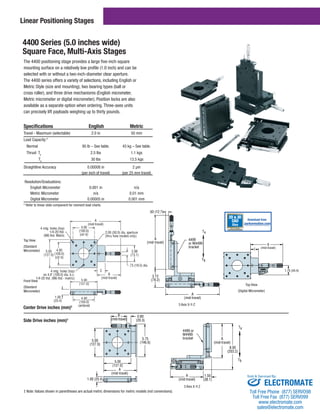
Dimensions inch (mm)
100-9274-01 XR Adapter Plate
A multi-axis adapter plate is available to
mount the ZP200 to an XR/LXR table or, mount an
XR/LXR table to the ZP200. This plate is 9.53 mm
thick and includes standard dowel pin holes for
repeatable alignment.
ZP200 as
Top Axis
ZP200 as
Base
404XR Yes n/a*
404LXR Yes n/a*
406XR Yes Yes
406LXR Yes Yes
206 Rotary Yes n/a*
*Not recommended - consult factory.
Download from
Sold Serviced By:
ELECTROMATE
Toll Free Phone (877) SERVO98
Toll Free Fax (877) SERV099
www.electromate.com
sales@electromate.com](https://image.slidesharecdn.com/baysidecatalog-140930093908-phpapp02/85/Bayside-catalog-74-320.jpg)


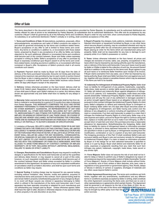
![Load Parameters
Evaluate the following requirements of the load:
Load inertia
Acceleration time (tacc)
Continuous run time (tcont)
Deceleration time (tdec)
Dwell time (tdwell)
Maximum continuous speed (Ncont)
From these, calculate:
Acceleration torque (Tacc)
Continuous run torque (Tcont)
Deceleration torque (Tdec)
Dwell torque (Tdwell)*
l
9 Step Procedure
*Although not used in the following torque calculations, torque requirements during dwell
(zero speed) must be considered when selecting gearhead size.
Duty Cycle
Determine if the application is to be considered as intermittent or
continuous by calculating the duty cycle as follows:
( tacc + tcont + tdec )
Duty Cycle= x 100
ttotal
If the duty cycle is 60%, and ( tacc + tcont + tdec ) is less than 20 minutes, the motion is
considered to be intermittent.
If the duty cycle is 60%, or ( tacc + tcont + tdec ) is greater than 20 minutes, the motion
is considered to essentially be continuous.
Calculate the Root Mean Cube Output Torque, Tmean.
Tacc
Tcont
Select a gearhead type; PS, PX, RS, Multi-drive, NE or NR
(Match gearhead frame size to motor frame size)
Review the catalogue listings and determine the gearhead size
(40 thru 300) which can meet the following criteria:
Tmean Tnomr
Tacc and Tdec Taccr
Determine the maximum rated input speed (Nmaxr)
for the selected gearhead.
Using Ncont. and Nmaxr from step 6, determine the
maximum allowable ratio as:
Max ratio = Nmaxr
Ncont.
Select an actual ratio from the catalogue listing and calculate the
mean input speed, Nmeani and the maximum input speed, Nmaxi,
as follows:
(Ncont)(t acc) + (N cont)(t cont) + (N cont)(t dec)
2 2
Note: Reflected inertia requirement may determine the actual ratio, as long as it does not
exceed the maximum value calculated in STEP 7.
CONTINUOUS INTERMITTENT
MOTION MOTION
Select factor KT and KS KS
Calculate (Tmean)(KT)(KS) (Tmean)(KS)
Determine that Tnomr (Tmean)(KT)(KS) Tnomr (Tmean)(KS)
Compare the required accelerate and decelerate torques, Tacc / Tdec,
to the rated accelerate torque, Taccr .
Taccr must be greater than the larger of Tacc or Tdec.
Check the Emergency Stop Torque rating.
Compare Nmeani with the nominal rated speed, Nnomr.
Nnomr must be greater than Nmeani
Compare the maximum input speed Nmaxi with the maximum
input speed rating, Nmaxr.
Nmaxr must be greater than Nmaxi
Verify radial and axial shaft load.
If any of these comparisons are not met, then:
Choose a larger gearhead
Reevaluate the ratio
Reevaluate the torque
Reevaluate the speed
Reevaluate the duty cycle
Reevaluate shaft load
SELECTION PROCESS IS COMPLETE!
Ncont
t total
Speed
t acc t cont t dec t dwell time
Torque
tacc tcont tdec tdwell time
Tdec
+
0
-
Tmean =
[(Tacc3)(Ncont)(tacc) + (Tcont3)(Ncont)(tcont) + (Tdec3)(t dec)]
2 2
[(Ncont)(tacc) + (Ncont)(t cont) + (Ncont)(t dec)]
2 2
3
Nmeani =
t acc + t cont + t dec
Nmaxi = (Ncont)(RATIO)
(RATIO)
2
3
4
5
6
7
8
9
ELECTROMATE
This gearhead selection is made available as an aid to selection of Parker Bayside Gearheads.
The values are merely an estimate and Parker Bayside cannot accept the responsibility for their interpretation. Parker Bayside standard product warranty supersedes all life estimates.
Toll Free Phone (877) SERVO98
Toll Free Fax (877) SERV099
www.electromate.com
sales@electromate.com
235
Sold Serviced By:](https://image.slidesharecdn.com/baysidecatalog-140930093908-phpapp02/85/Bayside-catalog-236-320.jpg)


Parker Hannifin is a Fortune 300 company and world's leading supplier of motion control components and systems. It offers customers electromechanical, hydraulic, pneumatic or computer-controlled motion solutions. Parker's team of engineers can integrate pneumatic, structural and electromechanical products into customized system solutions. It has factories globally to ensure fast delivery and the largest distribution network for quick support worldwide. Parker provides training and around-the-clock technical support for its motion control products and solutions.


