Download to read offline
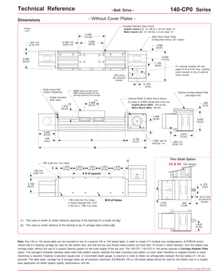
![Technical Reference - Belt Drive - 140-CP0 Series
Mounting Dimensions
inches
(mm)
Table Dimensions
inches
(mm)
Travel
Length
Table
Weight
Model
Number lbs
14x4004-CP0
14x4006-CP0
Footnotes:
(1)
- Without Cover Plates -
Belt
Weight
ounces
(gm)
1.3
(36,8)
B C
E M
inches
(mm)
A
4
8.0
14.0
1.188
(100)
(203,2)
(355,6)
(30,2) 3 8 6
10.0
16.0
0.313
(150)
(254,0)
(406,4)
(8,0) 5 12 8
12.0
18.0
1.313
(200)
(304,8)
(457,2)
(33,4) 5 12 12
16.0
22.0
1.438
(300)
(406,4)
(558,8)
(36,5) 7 16 16
20.0
26.0
1.563
(405)
(508,0)
(660,4)
(39,7) 9 20 20
24.0
30.0
1.688
(505)
(609,6)
(762,0)
(42,9) 11 24 24
28.0
34.0
1.813
(605)
(711.2)
(863,6)
(46,1) 13 28 30
34.0
40.0
1.063
(760)
(863,6)
(1016,0)
(27,0) 17 36 36
40.0
46.0
0.313
(910)
(1016,0)
(1168,4)
(8,0) 21 44 42
46.0
52.0
1.438
(1060)
(1168,4)
(1320,8)
(36,5) 23 48 48
52.0
58.0
0.688
(1215)
(1320,8)
(1473,2)
(17,5) 27 56 54
58.0
64.0
1.813
(1370)
(1473,2)
(1625,6)
(46,1) 29 60 60
64.0
70.0
1.063
(1520)
(1625,6)
(1778,0)
(27,0) 33 68 76.0
(1930,4)
82.0
(2082,8)
72
(1820)
88.0
(2235,2)
94.0
(2387,6)
84
(2130)
100.0
(2540,0)
106.0
(2692,4)
96
(2435)
112.0
(2844,8)
118.0
(2997,2)
108
(2740)
124.0
(3149,6)
130.0
(3302,0)
120
(3045)
39 80
45 92
51 104
57 116
63 128
0.500
(12,7)
0.875
(22,2)
0.313
(8,0)
0.688
(17,5)
1.063
(27,0)
x = 1; Carriage has 1 bearing; Carriage weight = 1.4 lbs. (0,64 kg)
x = 2; Carriage has 2 bearings; Carriage weight = 1.5 lbs. (0,68 kg)
Specifications subject to change without notice
1.5
(42,5)
14x4008-CP0
1.7
(48,2)
Dimensions & Specifications
14x4012-CP0
2.1
(59,5)
14x4016-CP0
2.5
(70,9)
14x4020-CP0
2.9
(82,2)
14x4024-CP0
3.3
(93,6)
14x4030-CP0
3.9
(110,6)
14x4036-CP0
4.5
(127,6)
14x4042-CP0
5.1
(144,6)
14x4084-CP0
9.3
(263,7)
14x4096-CP0
10.5
(297,7)
14x4108-CP0
11.7
(331,7)
14x4120-CP0 12.9
(365,7)
14x4048-CP0
5.7
(161,6)
14x4054-CP0
6.3
(178,6)
14x4060-CP0
6.9
(195,6)
14x4072-CP0
8.1
(229,6)
(kg)
4.8
(2,2)
(1)
5.3
(2,4)
5.8
(2,6)
6.3
(2,9)
7.3
(3,3)
8.3
(3,8)
9.3
(4,2)
10.3
(4,7)
11.8
(5,4)
13.3
(6,0)
14.8
(6,7)
16.3
(7,4)
17.8
(8,1)
20.8
(9,4)
23.8
(10,8)
26.8
(12,2)
29.8
(13,5)
32.8
(14,9)
Sold & Serviced By:
Toll Free Phone (877) SERVO98
Toll Free Fax (877) SERV099
www.electromate.com
sales@electromate.com
Weight shown is with a 1 bearing carriage [1.4 lbs (0,64 kg)], a NEMA 23 motor mount [0.34 lbs (0,16 kg)], and a H100 style [0.08 lbs (0,04 kg)] coupling.
When using a 2 bearing carriage add 0.1 lbs (0,04 kg) to each value.
ELECTROMATE
version: 01/2014](https://image.slidesharecdn.com/lintech140seriesspecsheet-141018112420-conversion-gate02/85/Lintech-140series-specsheet-3-320.jpg)
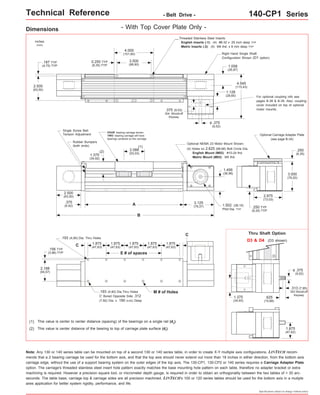
![Technical Reference - Belt Drive - 140-CP1 Series
Dimensions & Specifications
Travel
Length
Table Dimensions
Model
Number lbs
1.188
(30,2) 3 8 4
(100)
14x4006-CP1 1.5
1.438
(36,5) 23 48 42
(1060)
0.688
(17,5) 27 56 48
(1215)
1.813
(46,1) 29 60 54
(1370)
1.063
(27,0) 33 68 60
(1520)
Sold & Serviced By:
Specifications subject to change without notice
- With Top Cover Plate Only -
14x4004-CP1
Belt
Weight
ounces
(gm)
1.3
(36,8)
0.313
(8,0) 5 12 6
(150)
1.313
(33,4) 5 12 8
(200)
1.438
(36,5) 7 16 12
(300)
1.563
(39,7) 9 20 16
(405)
1.688
(42,9) 11 24 20
(505)
1.813
(46,1) 13 28 24
(605)
1.063
(27,0) 17 36 30
(760)
0.313
(8,0) 21 44 36
(910)
x = 1; Carriage has 1 bearing; Carriage weight = 1.4 lbs. (0,64 kg)
x = 2; Carriage has 2 bearings; Carriage weight = 1.5 lbs. (0,68 kg)
(42,5)
14x4008-CP1 1.7
(48,2)
14x4012-CP1 2.1
(59,5)
14x4016-CP1 2.5
(70,9)
14x4020-CP1 2.9
(82,2)
14x4024-CP1 3.3
(93,6)
14x4030-CP1 3.9
(110,6)
14x4036-CP1 4.5
(127,6)
14x4042-CP1 5.1
(144,6)
14x4048-CP1 5.7
(161,6)
14x4054-CP1 6.3
(178,6)
14x4060-CP1 6.9
(195,6)
(kg)
inches
(mm)
C
inches
(mm)
Mounting Dimensions
4.8
(2,2)
inches
(mm)
A
B E M
Table
Weight
(1)
5.3
(2,4)
8.0
(203,2)
14.0
(355,6)
5.8
(2,6)
10.0
(254,0)
16.0
(406,4)
6.3
(2,9)
12.0
(304,8)
18.0
(457,2)
7.3
(3,3)
16.0
(406,4)
22.0
(558,8)
8.3
(3,8)
20.0
(508,0)
26.0
(660,4)
9.3
(4,2)
24.0
(609,6)
30.0
(762,0)
10.3
(4,7)
28.0
(711.2)
34.0
(863,6)
11.8
(5,4)
34.0
(863,6)
40.0
(1016,0)
13.3
(6,0)
40.0
(1016,0)
46.0
(1168,4)
14.8
(6,7)
46.0
(1168,4)
52.0
(1320,8)
16.3
(7,4)
52.0
(1320,8)
58.0
(1473,2)
17.8
(8,1)
58.0
(1473,2)
64.0
(1625,6)
64.0
(1625,6)
70.0
(1778,0)
Footnotes:
(1) Weight shown is with a 1 bearing carriage [1.4 lbs (0,64 kg)], a NEMA 23 motor mount [0.34 lbs (0,16 kg)], and a H100 style [0.08 lbs (0,04 kg)] coupling.
When using a 2 bearing carriage add 0.1 lbs (0,04 kg) to each value.
ELECTROMATE
Toll Free Phone (877) SERVO98
Toll Free Fax (877) SERV099
www.electromate.com
sales@electromate.com](https://image.slidesharecdn.com/lintech140seriesspecsheet-141018112420-conversion-gate02/85/Lintech-140series-specsheet-5-320.jpg)
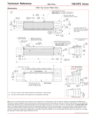
![Technical Reference - Belt Drive - 140-CP2 Series
Dimensions & Specifications - With Top Cover Plate Only -
Travel
Length
Table Dimensions
Model
Number lbs
14x4004-CP2
1.188
(30,2) 3 8 4
(100)
14x4006-CP2 1.5
1.438
(36,5) 23 48 42
(1060)
0.688
(17,5) 27 56 48
(1215)
1.813
(46,1) 29 60 54
(1370)
1.063
(27,0) 33 68 60
(1520)
Sold & Serviced By:
Specifications subject to change without notice
Belt
Weight
ounces
(gm)
1.3
(36,8)
0.313
(8,0) 5 12 6
(150)
1.313
(33,4) 5 12 8
(200)
1.438
(36,5) 7 16 12
(300)
1.563
(39,7) 9 20 16
(405)
1.688
(42,9) 11 24 20
(505)
1.813
(46,1) 13 28 24
(605)
1.063
(27,0) 17 36 30
(760)
0.313
(8,0) 21 44 36
(910)
x = 1; Carriage has 1 bearing; Carriage weight = 1.4 lbs. (0,64 kg)
x = 2; Carriage has 2 bearings; Carriage weight = 1.5 lbs. (0,68 kg)
(42,5)
14x4008-CP2 1.7
(48,2)
14x4012-CP2 2.1
(59,5)
14x4016-CP2 2.5
(70,9)
14x4020-CP2 2.9
(82,2)
14x4024-CP2 3.3
(93,6)
14x4030-CP2 3.9
(110,6)
14x4036-CP2 4.5
(127,6)
14x4042-CP2 5.1
(144,6)
14x4048-CP2 5.7
(161,6)
14x4054-CP2 6.3
(178,6)
14x4060-CP2 6.9
(195,6)
(kg)
inches
(mm)
C
inches
(mm)
Mounting Dimensions
5.0
(2,3)
inches
(mm)
A
B E M
Table
Weight
(1)
5.5
(2,5)
8.0
(203,2)
14.0
(355,6)
6.0
(2,7)
10.0
(254,0)
16.0
(406,4)
6.6
(3,0)
12.0
(304,8)
18.0
(457,2)
7.7
(3,5)
16.0
(406,4)
22.0
(558,8)
8.7
(3,9)
20.0
(508,0)
26.0
(660,4)
9.8
(4,5)
24.0
(609,6)
30.0
(762,0)
10.9
(5,0)
28.0
(711.2)
34.0
(863,6)
12.5
(5,7)
34.0
(863,6)
40.0
(1016,0)
14.0
(6,4)
40.0
(1016,0)
46.0
(1168,4)
15.6
(7,1)
46.0
(1168,4)
52.0
(1320,8)
17.2
(7,8)
52.0
(1320,8)
58.0
(1473,2)
18.8
(8,5)
58.0
(1473,2)
64.0
(1625,6)
64.0
(1625,6)
70.0
(1778,0)
Footnotes:
(1) Weight shown is with a 1 bearing carriage [1.4 lbs (0,64 kg)], a NEMA 23 motor mount [0.34 lbs (0,16 kg)], and a H100 style [0.08 lbs (0,04 kg)] coupling.
When using a 2 bearing carriage add 0.1 lbs (0,04 kg) to each value.
ELECTROMATE
Toll Free Phone (877) SERVO98
Toll Free Fax (877) SERV099
www.electromate.com
sales@electromate.com](https://image.slidesharecdn.com/lintech140seriesspecsheet-141018112420-conversion-gate02/85/Lintech-140series-specsheet-7-320.jpg)

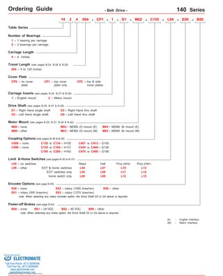
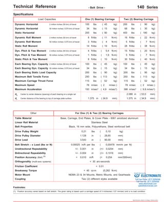
This document provides ordering information for belt drive systems in the 140 Series. It includes details on carriage length and travel length options, drive shaft configurations, motor and encoder mounting options, limit and home switches, couplings, and power-off brakes. Specifications are provided for load capacities, speeds, positioning accuracy, and other performance characteristics. Dimensional drawings show the mounting configurations and thru-shaft option.


![5G Explained! A High Level Overview [Introduction]](https://cdn.slidesharecdn.com/ss_thumbnails/5gexplainedahighleveloverview-260119165306-cc137a3e-thumbnail.jpg?width=640&height=640&fit=bounds)


