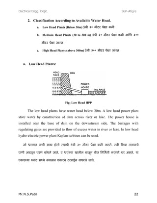
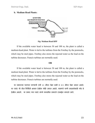
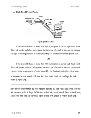
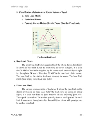
The document provides information about hydroelectric power plants including definitions, basic principles, components, and functions. It discusses:
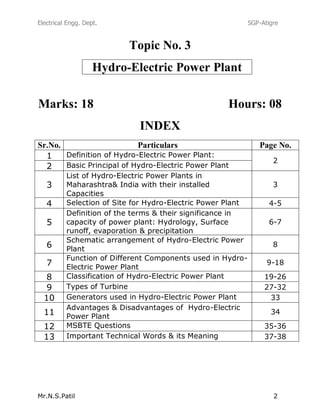
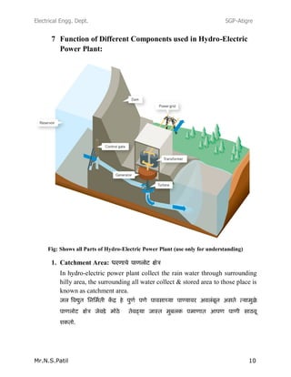
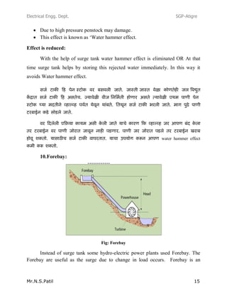
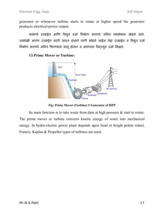
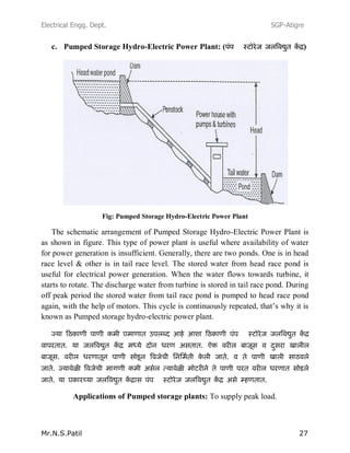
1) Hydroelectric power plants generate electricity by harnessing the potential energy of water stored at high elevations and converting it through a turbine into electrical energy.
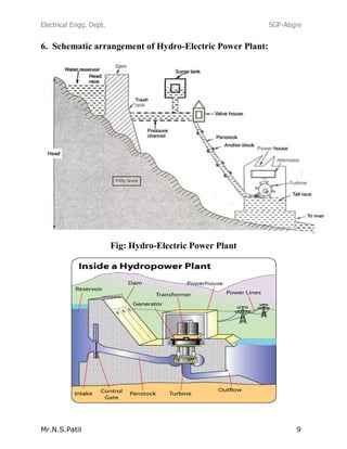
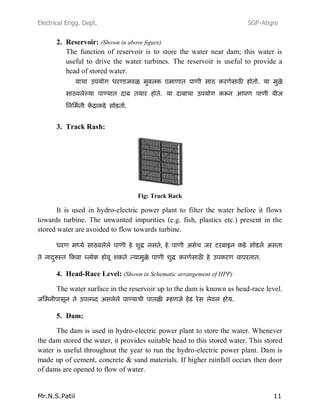
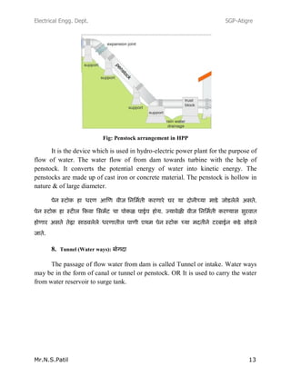
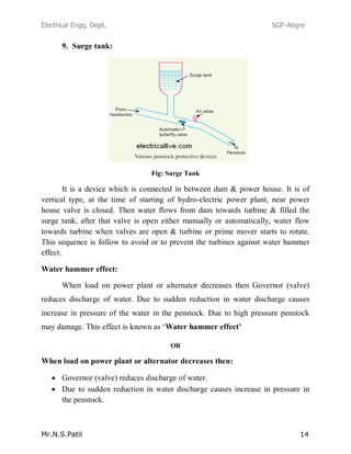
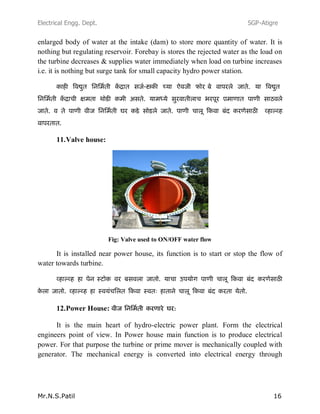
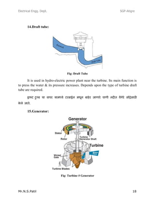
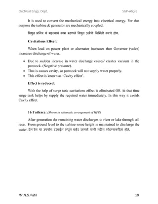
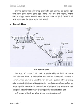
2) Key components include a dam to store water, penstocks to channel water to turbines, and a generator driven by the turbine to produce electricity.
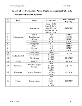
3) The selection of a suitable site considers factors like adequate water supply, terrain for water storage, transportation access, and proximity to energy demand centers.


![Power system planning & operation [eceg 4410]](https://cdn.slidesharecdn.com/ss_thumbnails/powersystemplanningoperationeceg-4410-130607134359-phpapp01-thumbnail.jpg?width=640&height=640&fit=bounds)


