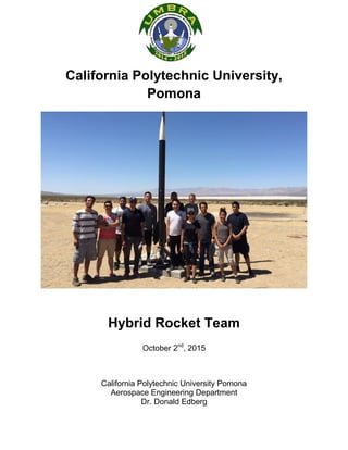
A group of aerospace engineering students at Cal Poly Pomona designed and built the university's first hybrid rocket. The rocket was designed to reach an altitude of 10,000 feet and have a maximum drift of 2,500 feet. After several failed launch attempts, the rocket finally launched but did not achieve its full altitude due to wind conditions. It is estimated the rocket reached between 2,500-3,000 feet before crashing due to parachute failure. The project provided valuable experience for the students in designing, building, and launching a large-scale rocket.
PFMEA, Risk Reduction and Effectiveness – Advance (AIAG FMEA #4 Edition)
Is your FMEA performing for you?
This is advance level of PFMEA, Have basic understanding fo Core IATF Tools before refering to this presentation.
An APM webinar promoted by the North West Branch Cumbria Chapter on 23 February 2022.
Speaker: Karl Sanderson
A root cause of project failure can be poor up-front shaping.
Facilitated Opportunity Framing at project inception, repeated through front-end-loading, mitigates the risk of later project recycle, ensures that the project is decision rather than task driven, and provides the right tools for optioneering. Framing is being rolled out across HM Government’s Major Projects Portfolio, and agencies such as the Nuclear Decommissioning Authority are taking the process even further by applying it more widely to their estates.
Topics covered included:
1. What is opportunity framing and how can it help make project outcomes more predictable;
2. Framing as a tool for achieving stakeholder alignment;
3. How framing fits into stage-gated project maturation – what it adds that is commonly missing;
4. The origins of framing, practitioners, and its current roll-out across the public sector;
5. Other uses of framing outside of projects including; policy formulation; strategic decisions; strategic procurements;
https://www.apm.org.uk/news/opportunity-framing-webinar/
https://youtu.be/4-WrVzHjzPA
Man marine diesel engine d2876 le 401 service repair manualjfjnse jmfkdm
This is the Highly Detailed factory service repair manual for theMAN MARINE DIESEL ENGINE D2876 LE 401, this Service Manual has detailed illustrations as well as step by step instructions,It is 100 percents complete and intact. they are specifically written for the do-it-yourself-er as well as the experienced mechanic.MAN MARINE DIESEL ENGINE D2876 LE 401 Service Repair Workshop Manual provides step-by-step instructions based on the complete dis-assembly of the machine. It is this level of detail, along with hundreds of photos and illustrations, that guide the reader through each service and repair procedure. Complete download comes in pdf format which can work under all PC based windows operating system and Mac also, All pages are printable. Using this repair manual is an inexpensive way to keep your vehicle working properly.
Service Repair Manual Covers:
Preface
Instructions
Engine type classification
Safety instructions
General notes on engine overhaul
Commissioning after engine overhaul
Fault table
Troubleshooting table
Engine views D 2876 LE401
Engine lubrication schedule
Fuel System Diagram
Cooling System Diagram
Engine management schedule
Fuel system
Cooling system
Lubrication
Vibration damper, flywheel
Intake / exhaust system
Cylinder Head
Valve timing
Crankgear, pistons
Attachments
Electrical system
Service Data
Special tools
Index
File Format: PDF
Compatible: All Versions of Windows & Mac
Language: English
Requirements: Adobe PDF Reader
NO waiting, Buy from responsible seller and get INSTANT DOWNLOAD, Without wasting your hard-owned money on uncertainty or surprise! All pages are is great to haveMAN MARINE DIESEL ENGINE D2876 LE 401 Service Repair Workshop Manual.
Looking for some other Service Repair Manual,please check:
https://www.aservicemanualpdf.com/
Thanks for visiting!
Legal Aspects of FMEA, overview of Canadian Law,
Due Diligence vs Negligence, Criminal Negligenced and what everyone needs to know about duty of care
www.6sengineering.com
This journal discusses the Mac OS operating system software. as for the history, various kinds of distribution mac os, introduction of mac os (for new users), features in mac os for desktop, and file management
DEVELOPMENT OF PARAFFIN BASED FUEL FOR HYBRID ROCKET MOTORJHUMKI NANDY
This project main finding was the high regression rate of paraffin with adding stearic acid, LDPE, EVA, carbon black, araldite and hardener. Regression rate was for three samples between 5-6mm/sec
Linear Static and Dynamic Analysis of Rocket Engine Testing Bench Structure u...IJERA Editor
This article presents a study of a testing bench structure for Rocket Engines, which is under development by the PUC-Minas Aerospace Research Group. The Bench is being built for civilian’s liquid bipropellant rocket engines up to 5 kN of thrust. The purpose of this article is to evaluate the bench structure using the Finite Element Method (FEM), by structural linear static and dynamic analysis. Performed to predict the behavior of the structure to the requests of the tests. The virtual simulations were performed using a CAE software with the Nastran solver. The structure is 979 x 1638 mm by 2629 mm, consisting of folded-plates (¼ "x 3¼" x 8") and plates of 1/4" and 1/2 ", both SAE 1020 Steel .The rocket engine is fixed on the structure through a set called engine mount. It was included in the analysis clearances or misalignments that may occur during tests. As well as, the load applied was evaluated with components in varying orientations and directions. It was considered the maximum size of the engine mount and the maximum inclination angle of load. At the end of this article it was observed that the worst stress and displacement values obtained were for the hypothesis with the inclination of five-degrees with load components in the positive directions of the axes defined and it was also obtained the first twenty frequency modes of the structure.
The Mission Concept Review affirms the mission need and examines the proposed mission's objectives and the concept for meeting those objectives. (Cited from NASA Procedural Requirements)
2. 2
Executive Summary
A group of Aerospace Engineering students in the Undergraduate Missiles Ballistics and
Rocketry Association was put together to construct Cal Poly Pomona’s first ever Hybrid Rocket.
Only one member out of this 15 people team had previous experience with rocketry so it was
expected for the group to run into problems and mishaps, but the main purpose was to use the
principles engineering learned in class and apply them to a real project on a bigger scale. Given a
set criteria of achieving a launch to 10,000 feet above ground level with a max drift of 2,500 feet
from the launch rail, the team came together and helped one another overcome obstacles which
even included an entire trip to the Mojave Desert where the rocket didn’t launch. The rocket was
to be propelled by a hybrid motor consisting of an oxidizer and a solid fuel in which this case the
oxidizer was nitrous oxide. Everything was built around the motor so that the center of gravity
and center of pressure can be adjusted to maintain optimum results. Two 4 foot carbon fiber
tubes were used with a 6 inch inner diameter that held two 4 foot card board tubes that contained
the frame of the inner rocket. The frame held the motor together and housed the electronics bay,
ejection charges, and the parachute, but most importantly the frame kept the entire rocket strong
enough to withstand all the forces including a crash landing.
After several failed attempts due to the ground support equipment not functioning as
planned, the rocket finally launched on the 5th
attempt during 15- 20 mph wind conditions where
it soon began to tilt and much of its vertical climb was lost due to the distance it was covering
horizontally. It is estimated the rocket reached a max altitude between 2,500 ft. and 3,000 ft with
a drift distance of 880ft. and a flight of 20 seconds before it crash landed due to the momentum
of the rocket tearing off the parachute during deployment. Unfortunately the data recovered was
not helpful because the datalogger did not register the correct data due to a malfunction which
was most likely caused by the crash landing. Several lessons were learned and a lot of experience
was gained during this project. The rocket might have crash landed, but not a single person on
the team gave up hope after so many failed attempts and the team was finally able to launch the
first ever Hybrid Rocket made at Cal Poly Pomona.
3. 3
Table of Contents
Section Page
Title Page 1
Executive Summary 2
Table of Contents 3
1.0 Introduction 4
2.0 Team members & Roles 5
3.0 Aerodynamic Analysis 6
3.1 Structural Analysis 8
3.1.1 Buckling Analysis 8
3.1.2 Lateral Load 12
3.1.3 Compression Analysis 16
3.2 Controls Analysis 20
3.3 Recovery System Analysis 22
3.3.1 Recovery System 22
3.4 Safety 28
4.0 Construction Design 33
4.1 Manufacture and Materials 36
4.2 Integrate Controls and Batteries 40
4.3 Parachute and Shock charges 41
4.3.1 Parachute production 41
4.3.2 Parachute ejection charges 43
4.4 Construction assembly 44
5.0 Testing 49
5.1 Electronics 49
5.2 Ground Equipment 49
5.3 Parachute 51
6.0 Procedure 53
6.1 Launch Pad 53
6.2 Ground Support Equipment 54
6.3 Flight Motor Assembly 56
7.0 Post Launch Summary 60
7.1 Results 61
7.2 Conclusions 69
8.0 Recommendations 81
9.0 Appendix 82
4. 4
1.0 - Introduction
Mission criteria
The project’s mission is to design and execute Cal Poly Pomona’s first hybrid rocket
using an M-class hybrid motor consisting of a liquid oxidizer and solid propellant. The rocket
design will also be able to reach a minimum apogee of 10,000 feet above ground level and a
maximum drift distance of 2,500 feet. The altitude will be measured with an altimeter. The
rocket shall be reusable and weigh no more than 50 pounds. The propulsion system should be
capable of throttle control and the entire rocket shall be recovered with minimal damage. This
project is designed to impart experience on building and constructing large rockets. Whether the
launch is successful or not, we hope to pave the way for future students at Cal Poly Pomona to
build upon and experiment with rockets of their own using ours as a foundation.
5. 5
2.0 Team members and roles
Moiz Khan - Team Leader
Josh Kennedy (Safety Officer) - Aerodynamics
Isaac Orozco - Aerodynamics
Guadalupe Romero - Aerodynamics
Miguel Lopez - Aerodynamics
Omar Benitez - Systems Engineering
Francisco Davila (Deputy) - Propulsion
Gerladson Evangelista - Propulsion
Tai Chi Kieu - Structures
John Tangan - Structures
Victor Sanchez - Structures
Arvin Artoonian - Recovery System
Fernando Sanchez - Recovery System
Alejandra Castellon - Controls
Austin Miller - Controls
The Aerodynamics group will be in charge of coming up with the calculations of drag
caused by the fin design and also the nose cone that is chosen. From their findings, the design
will be adjusted so the rocket can theoretically achieve its mission criteria.
The propulsion group will be working with the structures group to provide the forces that
are going to be seen on the structure of the rocket and how the structure will have to be modified
so it can take the load.
The Recovery System group will be designing an entire chute from scratch which will be
suitable for the hybrid rocket. They will find the drag caused by the chute to slow the rocket
down during descent to an acceptable velocity for the landing and the drift distance.
The systems engineering group will make sure all processes of the project are on task and
all the parts are available for the build. They will also be working with the controls group.
The controls group will be in charge of the rockets electronics which will control the
ejection charges and also collect data of the rockets flight characteristics.
6. 6
3.0 – Aerodynamic Analysis
The M-1000 motor is manufactured by Hypertek and made to produce 395 lbf of average thrust
with a 9.0 seconds thrust duration. This will definitely accelerate the rocket very quickly and the
aerodynamics must be sufficient so that this power is optimized in the vertical direction so the
maximum altitude can be achieved.
Drag coefficient can be determined experimentally or analytically, but first dynamic pressure is
found by
𝑞 =
1
2
𝜌𝑣∞
2
This gave us drag force
𝐷 = 𝑞𝐶 𝑑 𝐴
The main types of drag affecting a rocket are: skin friction which is caused by the kinematic
viscosity of air. Pressure drag, that is directly affected by the body geometry and wave drag
when a rocket reaches supersonic speeds.
Aerodynamics and stability are important on a rocket performance. The center of
pressure is the point through the sum of all aerodynamic forces act. To have a stable rocket the
CP should be aft of the center of gravity or CG. There are many ways to find the center of
pressure, one of them is by using the Barrowman Equations. There are some assumptions that
have to be made in order of using it. Small angles of attack, speeds lower than the speed of
sound, smooth airflow over the rocket, large length to diameter ratio, no discontinuities in the
body, axial symmetry, and thin flat plates.
𝑥 𝐶𝑃 =
𝛴𝐶 𝑁,𝛼𝑖 𝑥𝑖
𝛴𝐶 𝑁,𝛼𝑖
where the normal force coefficient 𝐶 𝑁,𝛼varies from with component geometry, each rocket
component i has its own center of pressure at 𝑋𝑖 from the nose cone tip. The total CP distance is
a weighted average of the component CP distances.
The problem with unstable rockets is that they can spiral out of control under small
disturbances, compared with stable rockets in which their trajectory is not perturbed by wind.
When rockets reach transonic and supersonic speeds, drag forces tend to increase, and want to
break apart the rocket. For strength, carbon fiber and slow curing epoxy was used on the body.
Also avoid large aspect ratios due to bending moments, which can lead buckle and failure of the
rocket structure.
7. 7
Rectangular cross section fins were used in the hybrid rocket. Fins are very important on
the design of a rocket; here are different types of fin designs and their characteristics.
Figure 3.0.1: Different types of fin designs.
8. 8
3.1 – Structure Analysis
3.1.1 Buckling Analysis of the Lower Tube:
Stress analysis is key to designing a vehicle capable of handling the great forces associated
with rocket flight. When the structure is loaded, it can collapse even if the stress is lower than
the yield strength of the material. This phenomenon is called Buckling. Buckling takes place
when the static load coincides with the specific load where elastic stability is lost. The shape of
the deformation at the critical load is called a Buckling Mode.
There are two methods for analyzing whether buckling will take place in a structure.
Apply an actual load.
Apply a unit load (1N)
Fig 3.1.1 shows a lower fuselage tube of the rocket, where the load of entire rocket weight
(155.7N) will apply on. Here, we need to make sure that the lower tube will not buckle before we
start to assembly the rocket.
Figure 3.1.1:
9. 9
Using Finite Element Method on CATIA V5 to Analyze the Tube Buckle:
In order to conduct the analysis, mesh needs to be applied to the tube. Here Constant-Strain
Triangular (CST) was used to divide the structure into small triangular units for analysis.
Figure 3.1.2: Meshing
Restraints and loads were applied to the column. The bottom edge was restrained with a clamp
with neither rotation nor displacement. An applied force of 155.7N was distributed on the top
edge since the entire rocket will connect to the lower tube to stand up on.
10. 10
Figure 3.1.3: Constraints and Loads
Static analysis was performed to obtain the Von Mises stress with the aim of comparing it with
the yield stress of the material of the tube to make sure it stays within in an acceptable range.
Figure 3.1.4: Statics Analysis
Buckling analysis was performed with a Number of Modes: 10, Maximum Iteration Number: 50,
and Accuracy: 0,001.
Figure 3.1.5: Buckling Analysis
11. 11
After compute by the computer, a result of 10 buckling mode was obtained with 10 critical load.
1st
Mode: Pcr = 9139,98N
Figure 3.1.6: 1st Buckling Mode
10th
Mode: Pcr = 27450N
Figure 3.1.7: 10th
Buckling Mode
12. 12
At this point, comparing the load from the entire structure to the critical load at the 1st
mode, it is
safe to assemble the part, since the load is much smaller compared to the critical load.
To evaluate sensitivity, the lateral load was also applied.
3.1.2 Lateral Load on the Tube
Similar to the longitudinal load, the displacement result for the lateral load was obtained as
Figure 3.1.2.1 below.
Figure 3.1.2.1 lateral Load
13. 13
10 buckling modes are obtained with 10 critical loads in lateral direction.
1st
Mode: Pcr = 2153,36N
Figure 3.1.2.2: Buckling Mode 1
15. 15
9th
Mode: Pcr = -2285,96N
Figure 3.1.2.4: 9th
Mode
Notice here, both positive and negative critical loads due to the lateral force can cause the
buckle on both sides of the column.
16. 16
3.1.3 Compression Analysis on the Fin
Since the entire rocket will be supported by 4 fins that are 900
from each other. One fin is
analyzed and symmetry is used to find the results for each one.
Figure 3.1.3.1: Geometry of the fin
Since the axial load applied on each fin will be the same, it can be assumed that each fin has
43.4N of force being applied on it.
Meshing is applied on the fin to begin using FEM, here CST is still being used to divide the fin.
17. 17
Figure 3.1.3.2: Meshing on Fin
Next step is applying the load and restrain on the fin. Here the load of entire rocket will be
divided by four since symmetry is used.
19. 19
After computing the element on the computer Von Mises stress’ is obtained to compare with the
yield strength and the principal stress’ of nodes on the fin.
Figure 3.1.3.5: Von Mises stress
Figure 3.1.3.6: Principle Stresses
20. 20
3.2 – Controls Analysis
The electronics used in the Hybrid Rocket were an Arduino Mega 2560 connected to a
10 degree of freedom sensor board from Adafruit and an SD card data logging board from
Adafruit. There was also an interconnected real time clock circuit for time stamping the data log
with each entry. This same computer was also the trigger for two parachute ejection pyrotechnic
charges initiated by relays. Two extra relays were used to transmit a roger beep during normal
operation and an alarm during parachute deployment over a 2-way radio.
Figure 3.2.1: Arduino Mega 2560
Figure 3.2.2: Adafruit 10 Degree of Freedom Inertial Measurement Unit
21. 21
Figure 3.3.3: Adafruit SD card data logging board with real time clock
During testing all aspects of the code were operating correctly. The accelerometer,
gyroscope, and magnetic compass were outputting data that was in range when moving the
device along the various axes. The barometric pressure sensor and temperature sensor were
also reading correctly compared with known local ambient conditions. The barometric pressure
sensor was a mission critical input device because it is required to calculate altitude which in
turn controls the timing of the parachute ejection.
22. 22
3.3 - Recovery System Analysis
3.3.1- Recovery System
The initial design of the recovery system was chosen to be dual deployment; however,
after careful analysis and consulting with Rick Maschek, a single deployment was preferred. The
single deployment method decreased the chances of failure and complexity of the system;
therefore, increasing the success rate of the recovery system.
The recovery system must manage the speed of the vehicle in order to keep the kinetic energy of
the rocket below 75 ft-lbf. A kinetic energy greater than 75 ft-lbf could result in the structural
failure and cause the vehicle to be non-reusable. The parachute size was determined by using
following equations:
𝐾𝑖𝑛𝑒𝑡𝑖𝑐 𝐸𝑛𝑒𝑟𝑔𝑦 = 𝐾𝐸 =
1
2
𝑚𝑣2
∑ 𝐹𝑧 = 𝐷𝑟𝑎𝑔 − 𝑊𝑒𝑖𝑔ℎ𝑡 = 𝑚𝑔 = 0
𝐷𝑟𝑎𝑔 = 𝑊𝑒𝑖𝑔ℎ𝑡 =
1
2
𝑝𝑣2
𝑆𝐶 𝑑
Performance of the recovery system also depends on the correct operation of the deployment
altimeters. The functionality of the recovery altimeters is tested using sample codes that mimic
similar tasks used for the recovery system. Overall verification of performance is achieved by
completing ground tests and launch test.
Parachute Diameter Calculation
Descent velocity:
𝐾𝑖𝑛𝑒𝑡𝑖𝑐 𝐸𝑛𝑒𝑟𝑔𝑦 = 𝐾𝐸 =
1
2
𝑚𝑣2
, 𝑣 = 𝑑𝑒𝑠𝑐𝑒𝑛𝑡 𝑣𝑒𝑙𝑜𝑐𝑖𝑡𝑦
𝐺𝑖𝑣𝑒𝑛 𝐾𝐸 = 75 𝑓𝑡 ∙ 𝑙𝑏𝑓
1
2
𝑚𝑣2
< 75𝑓𝑡 ∙ 𝑙𝑏𝑓
𝑆𝑜𝑙𝑣𝑖𝑛𝑔 𝑓𝑜𝑟 𝑑𝑒𝑠𝑐𝑒𝑛𝑡 𝑣𝑒𝑙𝑜𝑐𝑖𝑡𝑦 𝑤𝑒 𝑔𝑒𝑡:
𝑣 < √
2 𝑔 (75 𝑓𝑡. 𝑙𝑏𝑓)
𝑚
24. 24
Since the maximum allowable drift is 2500 feet from launch point, the drift between apogee and
the main parachute deployment can be calculated by subtracting maximum allowable drift from
Drift value from above equation.
𝐷𝑟𝑖𝑓𝑡 =
𝑎
𝑣
∙ 𝑤ℎ
𝑚𝑖𝑛𝑖𝑚𝑢𝑚 𝑑𝑒𝑠𝑐𝑒𝑛𝑡 𝑣𝑒𝑙𝑜𝑐𝑖𝑡𝑦 𝑓𝑟𝑜𝑚 𝑎𝑝𝑜𝑔𝑒𝑒 𝑡𝑜 𝑚𝑎𝑖𝑛 𝑑𝑒𝑝𝑙𝑜𝑦𝑚𝑒𝑛𝑡 𝑣 =
𝑎 ∙ 𝑤ℎ
𝐷𝑟𝑖𝑓𝑡
Using above equations and known parameters, the following was calculated:
Input Data
ρ at 13,000 ft (3962.4 m) 0.82 kg/m^3 0.0512 lb/ft^3
ρ at 10,000 ft (3048 m) 0.9093 kg/m^3 0.0562 lb/ft^3
Chute Drag Coeff. 1.5 Dome
shaped
0.75 Flat
sheet
Max KE 101.686346 Nm 75 lb.ft
Max Drift 762 m 2500 ft
Assumed wind speed 6.7056 m/s 22 ft/s
Altitude (est. peak) 3048 m 10000 ft
Altitude (true peak) 3962.4 m 13000 ft
Avg. Thurst 996.4539 N
Impulse 9835 N-s
Mass (boost) 17.5 kg 38.58 lb
Mass (coast) 13.5 kg 29.76 lb
Diameter 0.127 m 5.00 inch
burntime 9.87 sec
Results
Area 0.012667687 m^2
qb 376.4752509
burnout v 317.8196198 m/s
p 0.250376208
burnout alt 1875.223811
qc 150.858244
coast alt 1964.350196 m
max H 3839.574007 m 12,596.87 ft
Descent V (no chute) 3.88131986 m/s 12.7391236 ft/s
Chute Surface Area 11.27065885 m^2 121.1351487 ft^2
Chute Diameter 3.78817219 m 12.41910068 ft
Main Chute Drift 670.56 m 2200 ft
25. 25
Deployment of the Parachute
The single-stage recovery system is set to deploy at apogee (10,000 ft). The main parachute
ejects from the top of the upper body structure, just below the nose cone. This staging is
illustrated in Figure 3.3.1.
Based on the calculations, the diameter of
the parachute must be 12.4 feet in order to
have a soft landing. Each parachute cord
withstands 170 pounds of force. To
increase the strength of the cords, 2 cords
are used for each intersection. Two
ejection charges are used to ensure the
deployment of the parachute. The first
ejection charge is 4 grams of black
powder and the back-up ejection charge is
5.5 grams of black powder. The
secondary ejection charge is programed to
go off 2 seconds after the main ejection
charge.
Ejection Charges
In order to ensure separation and ejection of the parachute at the proper time, the altimeter is set
to light a two-foot low-current electric match. There are holes between the lower bulkhead and
altimeter compartment to allow the lead on each e-match through; the holes are shut with epoxy
to seal the chamber from the other chambers in the vehicle body. Improper assembly of an e-
match could result in electric shock and premature ignition of ejection charges.
Basic Ideal Gas Law is used to determine the amount of black powder needed.
𝑃𝑉 = 𝑁𝑅𝑇
𝑃 = 𝑑𝑒𝑠𝑖𝑔𝑛 𝑝𝑟𝑒𝑠𝑠𝑢𝑟𝑒 𝑖𝑛 𝑝𝑜𝑢𝑛𝑑𝑠 𝑝𝑒𝑟 𝑠𝑞𝑢𝑎𝑟𝑒 𝑖𝑛𝑐ℎ
𝑉 = 𝑣𝑜𝑙𝑢𝑚𝑒 𝑜𝑓 𝑐𝑦𝑙𝑖𝑛𝑑𝑟𝑖𝑐𝑎𝑙 ℎ𝑜𝑢𝑠𝑖𝑛𝑔 𝑐𝑜𝑚𝑝𝑎𝑟𝑡𝑚𝑒𝑛𝑡
𝑁 = 𝑚𝑎𝑠𝑠 𝑜𝑓 𝑝𝑜𝑤𝑑𝑒𝑟 𝑖𝑛 𝑝𝑜𝑢𝑛𝑑𝑠
𝑅 = 𝑢𝑛𝑖𝑣𝑒𝑟𝑠𝑎𝑙 𝑔𝑎𝑠 𝑐𝑜𝑛𝑠𝑡𝑎𝑛𝑡 (𝑖𝑛 • 𝑙𝑏𝑓/𝑙𝑏 𝑚)
𝑇 = 𝑖𝑛𝑖𝑡𝑖𝑎𝑙 𝑐𝑜𝑚𝑏𝑢𝑠𝑡𝑖𝑜𝑛 𝑡𝑒𝑚𝑝𝑒𝑟𝑎𝑡𝑢𝑟𝑒 𝑜𝑓 𝑝𝑜𝑤𝑑𝑒𝑟 𝑖𝑛 𝑅𝑎𝑛𝑘𝑖𝑛𝑒
𝑁 =
𝑃𝑉
𝑅𝑇
Figure 3.3.1: Flight Sequence
26. 26
Based on the above equations, the amount of needed black powder charge to deploy the 12 feet
parachute at apogee is calculated to be about 4 grams. Each black powder ejection charge
consists of a well of black powder contained in a plastic charge tube with the shroud of an e-
match immersed in the well.
Shock Chord
The shock cord used was a half-inch braided Kevlar Cord similar to the third cord from the left
shown in the Figure 3.3.2. The length of the cord needed was determined using a rule of thumb
from previous experience. The length was made to be 1.5 times the length of the rocket. This
made the length of the shock cord approximately 14 feet. The tensile stress applied on the shock
cord due to the load is important since keeping the parachute and body together is essential for
recovery. Kevlar stretches less upon separation and has a higher tensile strength making it a good
choice for the shock cord. The shock load on the cord was estimated to be about 492lbs. using a
method developed by a Ron Reese, the equation is below. Some reasonable approximations are
made for some of the variables. A recovery system manufacturer rated a rope with similar
material and construction at 7200 pounds. The cord is able to withstand the shock load
comfortably with strength to spare. The shock cord was tied to the body tube at all four metal
rods under the bulkhead with the metal plates seen in Figure 3.3.3. The parachute was then
secured by several knots tied to a carabiner as seen in Figure 3.3.4. The other end of the rope was
tied to a metal ring inside the nose cone. The parachute configuration looks similar to the one in
Figure 3.3.5.
Shock Load =
(−𝐵+√( 𝐵2−4∗𝐴∗𝐶)
4∗𝐴
A= (0.005 × Rope Stretch × Rope Length)/ Rope Load
B=-2 × A × Load
C = -Load × Fall Distance
Estimated values:
Rope stretch ≈2%
Rope Length= 14 ft.
Rope Load ≈720 lbs
Load= 35 lbs.
Fall ≈ 5 feet
27. 27
Figure 3.3.3: Parachute Deployment
Drift Calculation
The drift of the rocket is dependent on a few factors such as launch angle, weather cocking
during vertical ascent and drift after parachute deployment due to the wind. The parachute
calculations do not take in to account weather cocking. The following formula is the basis for the
single-stage parachute drift calculations:
∆𝐴 = 𝑐ℎ𝑎𝑛𝑔𝑒 𝑖𝑛 𝑎𝑙𝑡𝑖𝑡𝑢𝑑𝑒 𝑑𝑢𝑟𝑖𝑛𝑔 𝑡ℎ𝑒 𝑚𝑎𝑖𝑛 𝑑𝑒𝑝𝑙𝑜𝑦𝑚𝑒𝑛𝑡
𝑣 𝑚 = 𝑚𝑎𝑖𝑛 𝑑𝑒𝑠𝑐𝑒𝑛𝑡 𝑟𝑎𝑡𝑒
𝑣ℎ = ℎ𝑜𝑟𝑖𝑧𝑜𝑛𝑡𝑎𝑙 𝑤𝑖𝑛𝑑 𝑣𝑒𝑙𝑜𝑐𝑖𝑡𝑦
𝐷𝑟𝑖𝑓𝑡 =
∆𝐴
𝑣 𝑚
∙ 𝑣ℎ
The calculated result is 2200 feet which is within the requirement of 2500 feet radius.
Figure 3.3.2: Different shock cords
28. 28
3.4 - Safety
Materials Documentation
All hazardous chemicals and materials used throughout the course of this project will be
annotated with references leading to the Material Safety Data Sheet (MSDS). Digital
copies of all MSDS documents will be stored in a three ring binder will all MSDS sheets
will be kept in the main work facility in this case the jet engine lab. All chemicals and
explosives will be labeled and properly stored. Dangerous materials will label to clearly
identify it and provide information on its properties. All labels will have the exact title of
the corresponding MSDS to help the team locate a material in the google drive file or
three ring binder.
Facilities Involved
All facilities utilized by the team will have all necessary safety equipment as required,
depending on the chemicals and materials being dealt with. The team will be made aware
of all safety equipment and be instructed on the proper use for each one. Facilities will
include a briefing sheet that will state a concise summary of all pertinent hazards and
protocols. Facilities being used will include the jet engine lab and the Friends of Amateur
Rocketry (FAR) launch site located in Mojave California.
Team Member Responsible
The team member responsible for the execution of the safety plan and overall safety of
the team will be the safety officer. The designated safety officer for the team is Josh
Kennedy, a 2nd year Aerospace Engineering undergraduate student.
Procedure for NRA/TRA Personal
All personnel involved in the launch will abide by NAR High Power Safety Code which
will be stored in the google drive and the three ring binder. All personnel will follow the
procedure as stated below regarding hazardous materials handling and rocketry
operations.
The following safety procedures come from the High Power Rocket Safety Code 2012
edition.
● NAR/TRA members will only fly rockets, handle motors, and handle fuel within
the scope of their certification and training
● Rocket materials must be lightweight such carbon fiber, wood, foam etc, and
avoid excessive use of metal.
● Only commercially made motors are allowed.
29. 29
● Motors may not be tampered in any way.
● No heat source or open flame will be allowed within 25 feet of any motors.
● Only the fuel provided will be used, no homemade fuel will be used.
● The launcher must be 1500 feet away from any occupied building or public
highway.
● The motor will only be launched with an electrical launch system with electrical
motor igniters to be installed only at a designated preparing area.
● The launch system will have a safety interlock that is in series with the launch
switch that is not installed until the rocket is ready for launch, and will use a
launch switch that returns to the “off” position when released. The function of
onboard energetics and firing circuits will be inhibited except when the rocket is
in the launching position
● In the event of a misfire the safety interlock will be removed or disconnect the
battery then wait 60 seconds, only after 60 seconds may someone approach.
● Before launch the stability of the rocket will be checked.
● A warning system will be established.
● A check will be performed to make sure no one is in violation of the minimum
safe distance.
● When arming the rocket, no persons are to be on the launch pad except authorized
personnel.
● The rocket will be launched from a launcher that provides rigid guidance until the
rocket has attained a speed that ensures a stable flight, and that is pointed to
within 20 degrees of vertical.
● In the event of the wind exceeding 5 miles per hour a launcher of sufficient length
that permits the rocket to attain a safe velocity.
● A blast deflector will be used to deflect rocket exhaust from the ground and all
flammable material will be cleared from the launch zone.
● The motor shall not exceed 40,960N (9208 pound-second) of total impulse.
● The rocket will not weigh more than one-third of the certified average thrust of
the high power rocket motor.
● The rocket will not be launched into clouds, near airplanes, nor on trajectories
that take it directly over the heads of spectators or beyond the boundaries of the
launch site, and will not put any flammable or explosive payload in the rocket.
● The rocket will not be launched in winds in excess of 20 miles per hour.
● Safety personnel shall comply with Federal Aviation Administration airspace
regulations and make sure the rocket does not exceed any altitude restrictions.
● The rocket launch will take place outdoors in an open area where trees, power
lines, occupied buildings, and persons not involved in the launch do not present a
hazard, and that is at least as large on its smallest dimension as one-half of the
maximum altitude to which rockets are allowed to be flown at.
● The launcher will be 1500 feet away from any occupied building or any public
highway on which traffic flow exceeds 10 vehicles per hour, not including traffic
30. 30
related to the launch. The launcher will also be no closer than the minimum safe
distance.
● The rocket shall have a parachute that allows the rocket to return undamaged in a
condition allowing it to be flown again.
● Only flame retardant or fireproof wadding will be used in the rocket.
● The rocket shall not be recovered from power lines, tall trees, or other dangerous
places, fly it under conditions where it is likely to recover in spectator areas or
outside the launch site, nor attempt to catch it as it approaches the ground.
For all important phases of this project such as construction, assembly, launch, and
recovery a safety meeting shall be convened by the safety officer. The safety officer will create a
list of hazards before each meeting as well as a safety overview sheet. These sheets will be stored
on the team’s google drive folder as well as the three ring binder.
Methods for Including Safety Precaution Statements
In order to ensure the safest possible work environment the safety officer will continually
update the MSDS sheets, review upcoming plans and procedures, consult teammates on
hazard with their associated tasks, and ensure proper safety equipment is used. If
necessary hazardous equipment will have labels designating the appropriate Personal
Protective Equipment (PPE). Hazardous equipment will also have an attached briefing
sheets detailing risks and proper operation of the equipment.
Compliance with Federal, State, and Local Rocket and Motor Laws
Federal, state, and local laws regarding rockets, and motors, will be observed by the
members of the Hybrid Rocket Pro-Team. The team’s database will consist of a three
ring binder, and a Google Drive, containing the documents regarding these laws. The
documents in this database will contain information relevant to the Cal Poly Pomona
Office of Environmental Safety, the Occupational Safety and Health Administration
(OSHA), the Division of Safety and Health (DOSH), which is also known as Cal/OSHA,
the National Association of Rocketry (NAR), and the National Fire Protection
Association (NFPA). In the database, there will also be digital copies of NFPA 1127,
NAR High Power Safety Code, Federal Aviation Regulations (14 CFR, Subchapter F,
Part 101, Subpart C), and the Code of Federal Regulation 27 (Part 55: Commerce in
Explosives). The Hybrid Rocket Pro-Team will strive to meet the requirements set by
these laws. Every member of the team will become familiar with these laws, and
demonstrate knowledge of them before the production, and testing, of the Hybrid Rocket
begins.
31. 31
Possession of Rocket Motors
The task of purchasing, and obtaining, the rocket motors will be the responsibility of the
Hybrid Rocket Pro-Team’s certified rocket mentors. The team’s certified rocket mentors
include Matthew Ross (NAR Level 2), and Francisco Davila (NAR Level 1). All of the
team’s rocket motors, and propellants, will be obtained from licensed local suppliers.
Aside from purchasing, and obtaining, the rocket motors, the team’s certified rocket
mentors will also be responsible for storing the rocket motors at their residence. The
rocket motors will be stored in their original shipping containers, and they will be
transported, along with the fuel, within the trunk of a vehicle to the launch sites for
safety.
Student Compliance of Safety Regulations
The members of the Hybrid Rocket Pro-Team will be taught the safety guidelines, and
practices, necessary to ensure the safety, and well-being, of everyone involved in the
construction, and testing, of the rocket. If an accident ever occurs, the safety officer will
instruct the team members what to do to resolve the problem, and avoid further accidents.
The safety acknowledgement form contains the safety regulations stated below, and it has
been read and signed by every team member. This form which was signed by each team
member to launch at F.A.R can be found in Appendix B in Figure 9.1.
● Range safety inspections will be performed on each rocket before flight
● Every team member will accept the determination of the safety inspection
● If team members fail to accept determination they may be removed from the program
● The Rocket Safety Officer (RSO) will determine every issue regarding rocket safety
● The Rocket Safety Officer (RSO) can cancel any rocket launch for safety reasons
● Team members who fail to comply with safety guidelines will not be allowed to
participate in the launching of the rocket
Launch Day Safety:
Given the dangers of the rocket the following safety procedures were strictly observed before
both launch attempts:
· Top to bottom structural checks of the rocket
· Mounting and unmounting the rocket engine and fueling system
· Configuration of launch rail and mounting to rocket before launch
· Sufficient water to avoid dehydration at launch site
· Preflight checks of all launch equipment
32. 32
· Made sure everyone was in protective bunkers prior to launch
· Proper fueling and set up from a safe distance with the oversight of FAR personnel
· Proper countdown and warnings
· Proper defueling of rocket after aborted launch attempt
· Waited till rocket landed to leave bunkers
· Safe retrieval and removal of rocket motor
33. 33
4.0 – Construction: Design
The entire project was first brainstormed on paper and on a white board but as the choices
were becoming finalized, drawings using Solid Works were being created. The Solid Works
models allow for a better visualization of what needs to be constructed and the dimensions of
each object. This also allows for everyone on the team to see whether or not the parts will fit
together and exactly what size something needs to be made in order for the rocket to be
constructed properly. Below are some of the designs throughout the stage of the rocket which
were made and changed several times as the project progressed in the build stage. The solid
motor portion of the rocket was created so that it could be understood what dimensions the frame
must be so that the motor can easily slide in and out so that it can be reusable as shown in Figure
4.0.1
Figure 4.0.1: Motor Casing
The entire outer section of the body tube needed to be designed around the motor casing
and the frame so that the assembly can take place in the simulation. Once everything fits
perfectly, that allows the team to go ahead and order the parts needed such as the cardboard tube
from Public Missiles Ltd. which slides into the carbon fiber tube. The tube can be seen below in
Figure 4.0.2. The entire length of the solid and nitrous motor is 54.5 inches when assembled
together. They have a diameter of 4 inches and this is why the inner diameter of the bulkheads
must be 4 inches while their outer diameter must be 6 inches.
34. 34
Figure 4.0.2: Initial Rocket Body Tube with Nose Cone
The bulkheads are the primary component that keeps everything together in the structural
aspect of the rocket. They are 6 inch in diameter and the inner diameters are 4 inches which
allows the hybrid motor to slide in to the inner portion and the outer portion fits snug within the
6 inch inner diameter of the cardboard tube. Holes were drawn in the bulkhead which will allow
the steel rods to fit through and go throughout the body of the rocket giving it a strong and sturdy
structure. These designs can be seen below in Figures 4.0.3 and Figure 4.0.4.
Figure 4.0.3: Motor Support Bulkhead (Aluminum)
35. 35
Figure 4.0.4: Rocket Frame with Bulkheads
The fin design was a direct scaled down version of the German V-2 rocket fin. Initially
controlled fins were planned but with time constraints it was not achievable so the flaps were not
added to the final product although there was room left for the addition if everyone decided to go
forth with the plan. The fins were designed by looking off of blueprints of the V-2 fins found
online and scaling it down so that it would be sufficient for the Hybrid rocket. This design can be
seen below in Figure 4.0.5.
Figure 4.0.5: V-2 Fin Design on Smaller Scale for Hybrid Rocket
36. 36
4.1 - Construction-Manufacture/Materials
Bulkheads:
A number of plywood bulkheads were utilized to center the motor inside the body tube of
the rocket. Bulkhead dimensions were created using SolidWorks shown in figure 4.1.1 and
printed in actual size to allow for a simpler method to correctly achieve the right dimensions to
be cut out onto plywood. Once they were cut, the bulkheads were sanded down as needed in
order to be inserted into the rocket body tube with ease. Even though the diameter of the motor
was used to cut the bulkheads, the bulkheads were sanded to fit better around the motor. This
allowed the motor to be inserted through the bulkheads with less effort, and to still be held in the
center of the rocket body tube.
Figure 4.1.1: Bulkhead Dimensions created with SolidWorks
37. 37
Carbon Fiber:
Two cardboard cylinder tubes were used as mandrels for the rocket body tube, and sheets
of carbon fiber were wrapped around these tubes. Epoxy and hardener were used to bind the
carbon fiber to the tubes. The tubes were too large to be placed in an oven to cure the carbon
fiber, so they were dried at room temperature. Figure 4.1.2 below shows the carbon fiber
wrapped over the cardboard tube.
Figure 4.1.2: Tube wrapped with carbon fiber and left to dry
Steel Rods for Support:
Four steel rods were used to support, and space out, the bulkheads. In order to insert the
steel rods, each bulkhead had four holes drilled into it. These rods were held in place by a
washer, and a nut, on either side of the bulkhead. The most difficult part of inserting the steel
rods was to ensure that the holes drilled into each bulkhead were aligned correctly. At first, the
holes were not aligned, and this caused the steel rods to bend when they were inserted. This
problem was solved by using one of the bulkheads as a template, so that the drilled holes could
be aligned more easily as seen below in figure 4.1.3. The steel rods can be seen in figure 4.1.4
38. 38
which keeps the whole motor intact and provides great structural support for the rocket. The
completed structure can simply slide into the carbon fiber tubes.
Figure 4.1.3: Bulkhead used as template for other bulkheads
Figure 4.1.4: Steel rod structure
Cardboard Cylinder Tubes:
Two cardboard cylinder tubes were used to make the rocket body tube. At first, the team
planned to use a mandrel to make the rocket body tube exclusively out of carbon fiber. However,
39. 39
a mandrel with the diameter needed to house the rocket motor, and all the other components of
the rocket, could not be acquired. As a result, two cardboard cylinders with the desired diameter
were used as mandrels. Each cylinder was 4 feet long, and had a diameter of 6 inches. The
diameter of the cylinder is equal to the outer diameter of the bulkheads. All of the bulkheads
were sanded to fit slightly loose inside the cardboard tubes, so that they could be inserted easily
along with the motor inside the rocket body tube. Since the tubes were used as mandrels, they
became part of the rocket body tube because the carbon fiber wrapped around them could not be
removed. While building the rocket body tube, one of the cylinders was damaged, and a piece at
one end of it was missing. This problem was solved after the carbon fiber was placed over the
cardboard tubes because the carbon fiber hardened, and covered the damaged part of the tube.
Two tubes were used and each one was 6 inches in diameter and 4 feet long and can be seen in
Figure 4.1.5 below.
Figure 4.1.5: Cardboard tube
Fins:
The fins were constructed from a core of wood then laminated with two sheets of carbon fiber on
either side. This served to strengthen the fins while adding low drag. A final layer of carbon fiber
was used to attach the fins to the lower body tube. Several layers of epoxy were applied to
harden and form a smooth surface for airflow ensuring maximum aerodynamic performance. Fin
40. 40
manufacturing can be seen below which includes having the wooden pieces and then having the
carbon fiber cut outs which will be applied on them for reinforcement.
Figure 4.1.6: Applying epoxy to carbon fiber in order to adhere to plywood fins.
4.2 - Construction-Integrate controls/batteries
The main portion of the electronics is located above the liquid nitrous oxide tank. In this
section we focus on the electronics used for parachute deployment. These electronics consist of
an altimeter which is connected to a pair of electronic matches to set off the black powder
charges for the deployment of the parachute as shown in figure 4.2.1.
Figure 4.2.1: Electronics
41. 41
Above the charges shown in the diagram, a nomex blanket is used to cover the parachute
from any fire damage caused by charges explosions. Towards the center of gravity of the rocket
shown in orange, there were two set of mini cameras in figure 4.2.2, one facing up towards the
nose, and one facing down towards the fins of the rocket. These were used to record the launch,
parachute deployment, and landing.
Figure 4.2.2: Onboard camera
4.3 - Construction-Parachute/Shock Charge
4.3.1- Parachute Production
For the 12 feet diameter parachute with a 1 foot spill hole, Brand RIP Stop Nylon was used for
the material. The same material was used and tested by NASA Student Launch for the
competition and it was proven to be durable and strong. After cutting the fabric into proper
pieces, each section was attached to the other section by sewing the endings twice to ensure the
parachute would not rip apart due to applied forces. The recommended stitching length is 5% to
10% of the basic parachute diameter. After completely attaching all pieces, the parachute cords
were sewed on each endpoint of parachute. The technique used to attach the cords to the
parachute is as follows: two pieces of nylon were cut in a square shape. The sides of each square
were about 1 foot. The cord was placed in between two squares and was sewed in zig-zag format
then the nylon squares were attached to the endpoints of the parachute by sewing. Figure 4.3.1
shows how the parachute was made and Figure 4.2.1 shows how it looked when done.
43. 43
4.3.2- Parachute Ejection Charges
The materials needed for the parachute deployment were: shot gun shells figure 4.3.1, black
powder figure 4.3.2, and electronic matches figure 4.3.3. First a hole was drilled on the side,
towards the bottom of the shot gun shell where the electronic match was placed for ignition.
Figure 4.3.2.1: Shot gun shells Figure 4.3.2.2: Black Powder
The plastic tube was filled with black powder. In this case the rocket was quite large with
a diameter of six inches, because our University never made this size of rocket before, two shot
gun shell were used instead of one for redundancy. One filled with 2.8 grams, and the second
shell with 2.6 grams of black powder. These charges were connected to the altimeter of the
rocket, so when it reached apogee, the first charge will go off, and two seconds later the second
charge will be activated to make sure all the parachute was out of the rocket.
44. 44
Figure 4.3.2.3: Electronic matches
4.4 - Construction-Assembly
Assembly - Motor with bulkheads and steel rods:
To assemble, the rocket bulkheads were used in order to keep the motor in place, and
steel rods were utilized in order to distribute the load on the bulkheads (Figure 4.4.1). Each
bulkhead was positioned at a certain point on the steel rods, so that the motor could be held in
place by the bulkheads at different points. Steel plates were also added in between the washers
and the bulkhead at the end of the motor (Figure 4.4.2). This was done to ensure that the
bulkhead had enough support to keep the rocket from going right through the wood.
45. 45
Figure 4.4.1: Motor assembled with bulkheads and rods
Figure 4.4.2: Steel plates for reinforcement
46. 46
Assembly - Carbon fiber fins:
The fins of the rocket were cut out of plywood, and the dimensions of the fins were
designed using SolidWorks. A two dimensional sketch was created, and printed out to be used as
a template. After the template was used to cut out the fins, the fins were covered in carbon fiber
and then aligned on the rocket after it dried (Figure 4.4.3). A plastic cover was then placed over
the fins covered in carbon fiber so that air bubbles would not form. Even though the plastic cover
remained on the fins until the carbon fiber dried, air bubbles still appeared on some of the fins.
This problem was solved by sanding the fins to remove the air bubbles, and then applying
another coat of epoxy. The fins were also sanded to remove excess carbon fiber on their edges,
the sanded fins can be seen in Figure 4.4.4.
Figure 4.4.3: Fin aligned on tube
47. 47
Figure 4.4.4: Sanded fins
Assembly - motor and body tube:
After the body tube was finished and the motor was encased in the structure the two were
put together. Sliding the bulkhead/motor into the body tube was not too difficult; it was just a
case of making sure the bulkheads were aligned properly with the steel rods in order to slide
easily into the body tube (Figure 4.4.5). These bulkheads were all hand cut so they weren’t
perfect in size as it would have been if they were laser cut but the team decided to go ahead and
manually cut them to get some good experience. The demanding part of this assembly was
getting screws to attach the rocket body tube to the bulkheads. Unable to see where the
bulkheads aligned with the body tube it became clear a method for deciding where to drill was
needed. This led to the idea of measuring the bulkhead distances prior to sliding the
motor/bulkhead into the body tube. In order to assure the holes drilled in the body tube were
aligned to have the screws drill into the bulkheads, a regular piece of paper was utilized. By
48. 48
simply wrapping the piece of paper around the body tube and taping it so its ends would align a
method for creating aligned holes for the bulkheads was achieved (Figure 4.4.6).
Figure 4.4.5: Half of the motor after being slid onto the body tube of the rocket
Figure 4.4.6: Process of drilling holes onto the body tube of the rocket in order to screw
the body tube onto the bulkheads
49. 49
5.0 - Testing
5.1- Electronics Testing
The parachute deployment and data logging system used an Arduino with barometric
pressure sensor, accelerometer, magnetic compass, and gyroscope sensors, an SD card, and
electronic relays. The Arduino was programmed to use barometric pressure to calculate
approximate altitude. When a drop in altitude was detected, the Arduino would turn on one relay
and then another a few seconds later. These relays were connected to electronic matches in two
different ejection charges.
This system was tested by being assembled inside a small box with lightbulbs installed
instead of electronic matches/ ejection charges. The box was tied to a string and lowered from
the top of a flight of stairs roughly 8 feet. The system was confirmed working because the lights
would illuminate when the box was descending. This was also confirmed by the data log on the
SD card installed in the Arduino.
5.2 – Ground Equipment Testing
Rick Maschek was present during the ground equipment testing because he was
the only one who owned all of the equipment which costs upwards of over $1,000. The
team needed rick to come down to Cal Poly Pomona and go over the procedure so
everything was brought down except for the oxygen and nitrous tanks. This was later
found to be a problem because on launch day the tanks were the reason the team were
having failed attempts since the solenoids were not functioning correctly.
The ground equipment consisted of the following:
• Launch Stem; a coaxial tube with adjustable mount that fits to the launch rod or rail and
has male 4AN fittings for the gaseous oxygen and nitrous oxide lines.
• Gaseous oxygen (GOX) line; a 10-foot stainless steel-braided hose with red female
4AN fittings.
• Nitrous oxide line; a 10-foot stainless steel-braided hose with blue female 4AN fittings.
• Nitrous oxide Solenoid Assembly; consisting of fill solenoid, dump solenoid, blue male
4AN fitting, and CGA 326 tank fittings for industrial nitrous oxide tanks. CGA 660 tank
valve fittings for hot rod nitrous oxide tanks are an available option.
• GOX Assembly; consisting of an oxygen regulator, CGA 540 tank fitting, solenoid
valve, check valve and a red female 4AN fitting.
• Ignition module; 7500VDC output generates an arc across the ignition wire for ignition
of the fuel grain. Fuse-protected, comes with spare fuses.
50. 50
• Launch Controller; equipped with Safe & Arm key switch, LED power indicator, three-
position rotary switch for Fill/Dump/Fire functions, and momentary toggle actuator
switch. Reverse polarity protected.
• Satellite Control Box with color-coded sockets; two outlets for the nitrous oxide fill and
dump solenoids, plus outlets for the GOX solenoid and ignition module.
• 100 foot 3-prong extension cord for connecting the launch controller and satellite
control box.
• One roll of 24 gauge 2-conductor ignitor wire.
The Ground Support Equipment performs three functions, each of which is controlled remotely
via the launch controller:
• filling of the flight oxidizer tank
• dumping of the flight oxidizer tank in the event of an aborted launch
• non-pyrotechnic ignition of the motor
The equipment testing follows as below:
1. Split and strip insulation from one end of a 4 inch piece of ignition wire. Twist the
stripped wire ends to avoid fraying. Cut
the other end straight across – make this a clean cut with sharp scissors or cutters.
2. Attach the stripped ends to the alligator clips of the ignition module, and let the cut end
dangle where it is
visible. Make sure that the alligator clamps are not shorted together and that the wire or the clips
are not in contact with
you or anything else.
3. Fully open the oxygen tank valve and adjust the regulator to between 80 and 100 psi. If
you hear any leakage, turn the
oxygen off and make sure the fittings are tightened.
4. Fully open the nitrous oxide tank valve and verify that there are no leaks. Remember that
nitrous oxide tanks without
siphon tubes must be mounted upside down to allow liquid nitrous oxide to flow into the oxidizer
tank.
5. Set launch controller switches as follows: Safe/Arm key switch on Safe, rotary switch on
Fill (top) position, and activate
switch Of.
6. Attach the battery cables to a 12V DC source capable of supplying at least 10 amps.
Either a car battery or a gel-cell
battery will be adequate. Please note that the launch controller circuitry is reverse-polarity
protected and the clips may be
attached either way to the power source.
7. Turn the Safe/Arm key switch to the Armed position. The indicator light should now be
on.
8. Make sure that the launch pad area is clear prior to checking the oxidizer fill system.
Briefly push the activate toggle switch
51. 51
up and nitrous oxide should be released from the launch stem. As nitrous oxide escapes from the
fill tube, the vaporizing
liquid plume should be easily visible. Release the toggle switch.
9. Move the rotary switch to the dump position, and activate the toggle switch. The dump
solenoid clicks as it opens - listen
for the sound (no nitrous oxide will be released). Release the toggle switch.
10. Double check that the ignition wires are clear of any part of the GSE or other materials,
and especially away from you!
Move the rotary switch to the fire position, and activate the toggle switch. A steady high-voltage
arc should be seen at the
end of the ignition wire, and oxygen should be heard escaping from the start oxidizer tube. Do
not place any part of your
body near the ignition circuitry while this test is in progress – serious electric shock could result.
5.3- Parachute Testing
Parachute Cords:
A drop test was performed to ensure the strength and durability of the cords. A 1.5 foot Braided
Mason Line 100% Filament Nylon Cord was attached to a 20 lb weight and was dropped to test
its strength. Based on the test results the strength of the cord was estimated to be 165-172 lbs.
For each endpoint, two cords were used instead of one. Since the parachute consists of 6
endpoints, the force applied by the weight of the rocket at the moment of deployment gets
distributed between the six cords. Doubling the cords decreases the distributed force by a factor
of 2.
Figure 5.3.2: Drop test to determine the
strength of the parachute cord
52. 52
Ejection Charge:
An ejection charge test was performed to confirm the calculated amount of black powder
was enough and if the nose cone and parachute would deploy properly. This test was done by
securing the upper body tube and enabling the ejection charges by a long wire from a safe
distance. The calculated amount of black powder and the test results were in agreement. A
secondary ejection charge with a higher amount of black powder was also placed next to the
main ejection charge with a 2 second delay to ensure the parachute would be deployed.
Figure 5.3.3: Ejection Charge Test
53. 53
6.0 - Procedure
6.1 Launch Pad
At FAR, there were many different types of launch pads to choose from. We
chose the one most adequate for our rocket.
A jack was used to lower the launch rail to a horizontal position.
The launch stem assembly was placed on the launch rail with C-clamps for the
connection of the nitrous oxide lines.
Figure 6.1.1: Rocket on one of the many launch rails at F.A.R
54. 54
6.2 Ground Support Equipment
The Nitrous Oxide tank had to be taken out in a cooler filled with ice due to the
hot weather (over 108 F).
Figure 6.2.1: Team preparing rocket and keeping the nitrous tank cool in the ice cooler
The nitrous oxide solenoid assembly was mounted onto the nitrous oxide tank.
The tank fitting which connects the tank valve to the solenoids was to be
moderately tight. The nitrous oxide line was attached afterwards.
The GOX assembly was mounted on the oxygen tank and attached the oxygen
line (with red AN fittings) to the regulator. Due to recommendations, the oxygen
bottle was laid on its side to prevent damage to the valve or regulator in case it
was knocked over by accident.
55. 55
Figure 6.2.2: NOS and GOX Solenoid Assembly along with the Launch controller box to
the left
Launch stem assembly was used which was placed on the launch rail in order to
connect the nitrous oxide line (blue fitting) to the nitrous oxide fitting on the
launch stem (blue fitting). We proceeded to connect the oxygen line (red fitting)
to the oxygen fitting on the launch stem (red fitting).
The oxygen tank and the nitrous oxide tank were placed about six to eight feet
from the launch stand, with no kinks or tight bends in the hoses as seen being
worked on in Figure 6.2.1.
Connection of the satellite control box to the launcher. The box had two duplex
outlets. The duplex outlet with brown and white outlets was for the nitrous oxide
solenoids. The black outlet was for the ignition module, and the green outlet was
for the oxygen solenoid. Plug the nitrous oxide dump solenoid (white plug) into
the white nitrous dump outlet. The team plugged the nitrous fill solenoid (brown
plug) into the brown nitrous fill outlet. Then, we plugged the oxygen solenoid
(green three-prong plug) into the green ignition oxygen outlet. Finally the team
was able to plug the ignition module (black three-prong plug) into the black
ignition spark outlet.
The satellite control box was plugged onto an extension cord that had the correct
voltage to prevent it from igniting again, and run the extension cord to the launch
control area.
The launch controller was connected to a 12 volt battery.
The ground setup equipment was tested one final time before proceeding.
56. 56
Figure 6.2.3 Assembly of Ground Support
6.3 Flight Motor Assembly
Igniter wire of about 24” long was cut and separated the wires at one end and
stripped about 1⁄2” of insulation from each. Then it was twisted so that each wire
would prevent from fraying.
Igniter wire was taped to the launch stem leaving a little extra at the top so the top
end could be trimmed. The top end of the wire was about 1” from the top of the
nitrous oxide fill tube.
57. 57
o The wire was trimmed by making a clean, straight cut as we did for GSE
testing. It was double checked that the cut end was positioned about 1”
from the top of the fill tube and bent the cut end outward slightly.
Figure 6.3.1: Igniter wire being taped onto the Launch Stem
The 10 ft. rocket was carried out in the scorching hot weather by one of the team
mates. WD-40 was used to clean and lubricate the launch rail.
The rocket was then slid down the launch rail.
58. 58
Figure 6.3.2: Rocket being slid down the rail with the launch buttons
Carefully the launch stem was inserted up through the fuel grain. When the fill
tube (the center coaxial tube) passed through the Kline valve O-ring, the team was
able to feel it sit against the injector body indicating correct feeding.
The tie-straps were inserted through the slots in the fuel grain, and looped one
around each protruding bolt on either side of the stop collar on the drop stem. The
tie-straps were joined at the ends and cinched up tightly to pull the drop stem
firmly towards the motor.
Once again, a jack was used to now lift the launch rail into a vertical desired
position as show in action in Figure 6.3.1.
Finally Rick Maschek opened the nitrous oxide and oxygen tank valves and were
ready for launch with the safety officer watching out and making sure everyone
was a safe distance away!
59. 59
Figure 6.3.3: Ground equipment setup and attached to the rocket motor
The nitrous tank can be seen laying in an ice cooler with ice to keep it at a cold temperature in
the picture above. The rest of the ground equipment can be seen except for the oxygen tank
which was kept on the other side away from the nitrous.
Figure 6.3.1 Jack lifting of rocket to desired horizontal positioning
60. 60
7.0 - Post Launch-Summary
The hybrid rocket successfully launched after two unsuccessful attempts on August 15,
2015. Although there were various flaws in our overall launch, the rocket, however, did meet
many of the team’s goals. For example, although the parachute detached from the rocket on its
way down, it did successfully deploy as programmed. In addition, the rocket did not meet the
10,000 foot altitude requirement, but it did reach an altitude of between 2,500-3,000 feet.
Overall, this project was a huge feat for Cal Poly Pomona as it was the first hybrid rocket ever
launched by any students at Cal Poly Pomona and will hopefully set a strong precedent for future
rocket project teams to build from.
61. 61
7.1 - Post-launch-Results
Shortly after the launch the rocket started tilting due to its stability and weather cocking.
The center of pressure and center of gravity of the rocket were too close; therefore, as the rocket
burned its fuel, the center of mass started to shift and the rocket became unstable. Weather
cocking also affected the direction of the flight since the horizontal wind velocity rotated the
vehicle to where it had a new flight direction into the wind. These two factors combined caused
the rocket to tilt until it started descending. The altimeter sent a signal notifying the change in
altitude is no longer positive which triggered the ejection charges to deploy the parachute. At this
point the rocket had a downward coast velocity. The parachute deployed; however, due to the
rocket’s high velocity, the parachute cords did not withstand the exerted forces and they snapped.
All 12 cords were disconnected as shown in the Figure 7.1.0. The chosen cords were designed to
be used at apogee when the velocity of the rocket was at its minimum. Each cord was capable of
withstanding about 170 lbs. The opening shock, also known as the jerk, was much greater than
expected since the rocket became unstable and did not reach a near-zero velocity at apogee. This
exerted force was greater than the breaking point of Braided Mason Line Cord and caused the
parachute to fail.
Figure 7.1.0: Shock cord tied to carabiner
Aside from mechanical problems during the fueling and launch, the rocket flew correctly
and the electronics appeared to work because at least one parachute ejection charge explosion
and smoke was seen. This was followed by the parachute deploying. Unfortunately, the
parachute strings snapped and it was disconnected from the rest of the rocket; thus, causing the
rocket to land hard.
The flight computer was still functioning when the rocket was recovered and was
switched off so that the SD card could be removed and data recovered. The data file was intact
when loaded into the computer, however there were numerous issues.
62. 62
Data Issues:
1) Barometric pressure and altitude values hardly changed throughout entire flight time.
2) No data point was marked for parachute deployment command. A program was
specifically written for a part of the code which would insert the altitude at ejection event into
one cell in an empty column of the data file. This data point was missing. This leads to two
conclusions:
a) The computer worked correctly and triggered the parachute when the rocket
started falling and somehow the data file was incomplete.
b) The computer was not working correctly and the ejection was triggered by an
electrical failure mid-flight.
3) Accelerometer, gyroscope, and magnetic compass data looks correct but seems like the
time is incorrect. Our data graphs were compared to other rocket flights and it looks similar. The
main issue here is that the entire flight was only around 20 seconds long, yet the data log shows
the changes in the datalog indicating extreme motion over much longer periods of times
(minutes).
In conclusion, the data is not useful for anything with a degree of certainty. One of the
biggest problems realized is the data sampling rate. The code sampled data once every 3 seconds.
It should have been sampled at an incredibly higher rate. At a higher rate it would be possible to
detect false readings from true readings. Unfortunately the data that we were left with isn't
specific and is very inaccurate. The temperature appears to fall at random when it should be
constant or increasing. The pressure and altitude seem to be changing when the rocket would
have been standing still. The inertial measurement events last too long before returning to a
steady state value. The only thing known for sure about the data collection is that it is impossible
to interpret. It is very possible the crash at the end of the flight caused a major computer failure
and the data log was affected somehow. Based on estimates from watching previous people at
F.A.R launch their rocket, it is believed the Hybrid Rocket reached a max altitude between
2,500 ft. to 3,000 ft. It was also found that the drift distance of the rocket was about 880 ft. from
the launch stand which meant the rocket tilted quite a bit on its way up which is one reason why
the max altitude is not as high as planned.
63. 63
Figure 7.1.1: Electronics bay before flight (left) and after flight (right). Major damage to
the rocket frame surrounding the electronics can be seen.
Even without data we can be fairly certain the parachute ejection system did work
correctly because of one loud POP (00:12 in video) followed by a second quieter POP (00:13)
which could be heard less than one second later on the video. Smoke can also be seen after each
POP. The computer was programmed to fire one charge and then another approximately 800
milliseconds later. Because the video timing lines up exactly with the computer code, as
excerpted below, we believe the ejection control system worked correctly.
if((difference<-x) && (alt>control) && ecc==0)//where x is the minimum limit for the negative
change in altitude. The combo of these difference<x and alt>control prevent premature deploy.
{
float ejection_event = alt; //altitude at which the ejection charges fired
logfile.print(", ");
logfile.print(ejection_event);
digitalWrite(4,HIGH); //turn on relay connected to pin 4 (relay 1)
delay(800);
digitalWrite(5,HIGH); //turn on relay connected to pin 5 (relay 2)
delay(5000);
Code excerpt highlighted in yellow are the commands that close the relays energizing the
explosive charges for the parachute ejection. The line "delay(800)" is an 800 millisecond delay
between firing the first and second charges. The second charge is meant as a redundancy in the
event the first charge is a dud.
67. 67
Figure 7.1.8: Puff of smoke (in purple circle) after first audible POP frame capture from
00:12 in video
68. 68
Figure 7.1.9: Video frame capture
From the figure above it can be seen that at 00:14 seconds of flight it is showing initial
smoke puff (purple), cone (yellow), and light wisp of smoke after second audible POP. The
rocket body can be seen just under the red circle as a black spot.
69. 69
7.2 - Conclusions
June 20th
was the first attempt of Cal Poly Pomona’s hybrid team to launch their first ever
Hybrid Rocket. It was difficult to ascertain the source of the failure; however, a voltage from the
shoddy extensions is the most likely suspect. There were simply too many problems with the
ground equipment and setting up the wiring out in the heat which took a long time. During this
time the nitrous oxide tank was warming up since all the ice had melted away and it was pretty
much useless to use the nitrous. Time was of great issue and when the team was ready to retry
again, the airspace was no longer cleared for us since it was 5:00PM and our time slot was over
to launch anything up in the air. There was no choice, but to come back another day and keep
trying.
The team practiced the ground equipment setup several times while they waited a few
weeks to return and attempt the launch again. This time the team knew what problems could rise
and how to overcome them. Once all the equipment was setup the launch controller was set to
“fill” in which the nitrous could be heard filling into the rockets oxidizer tank. However, when
the fire button was pressed, nothing happened and the rocket needed to be taken down once more
to figure out what went wrong. It was apparent that the Launch Stem, pictured below in Figure
7.2.1, was not inserted all the way into the inlet fitting of the oxidizer tank so all of the nitrous
was being leaked out into the atmosphere which was not visible because of the extreme heat on
launch day.
Figure 7.2.1: Launch stem inserted in motor
70. 70
A small piece of tape used to keep the igniter wire on the launch stem was blocking the
path of the end of the stem to insert itself correctly. Once this problem was fixed, the second
attempt on this day was set to go and this time the nitrous was being filled correctly but the
oxygen tank was not dumping oxygen for the igniter to burn enough. This seemed to be the same
problem that occurred on the first launch attempt a few weeks back. This time it was figured that
a voltage drop was occurring once we lowered the rocket down and did a quick ground
equipment check with the Launch stem disconnected. It was found that the extension cord was
encountering too much resistance and had been exposed to too much extensive heat so the
oxygen tank solenoid was not firing due to voltage not being available after the drop. Figure
7.2.2 shows the rocket being taken down one last time.
Figure 7.2.2: Last adjustments on the rocket
71. 71
Figure 7.2.3: Oxygen tank connected to the launch stem
A much bigger extension cord, which was capable of carrying a bigger load was grabbed
quickly from the F.A.R bunker and it replaced the old one. The entire launch procedure was then
repeated and the nitrous was filled for a total of 3 minutes and 30 seconds which is the required
time to fill the tank and the fire button was then pushed. The igniter burned up and a lot of fire
was seen but the rocket stayed on the stand for about 7 seconds before exhaust flames started to
be visible. Even once the exhaust flames were visible, the rocket did not leave the stand for
another 3 seconds and then it finally took off.
73. 73
Figure 7.2.5: Take-off
The rocket was ripped off of the launch buttons because the rail buttons were found to be intact
on the rail after the launch. The rocket started to tilt about a second into flight and then the
horizontal component became greater as the rocket climbed higher. The ejection charges were
fired through the Arduino program, however, the parachute was ripped off due to the momentum
of the rocket in the horizontal direction so the rocket crash landed. The parachute ejection can be
seen below in figure 7.2.6. If the rocket was to deploy soon after apogee with less momentum,
the parachute would have been able to slowly descend the rocket to a soft landing.
74. 74
Figure 7.2.6: Parachute ejection
The rocket crash landed and the data retrieved came out to be extremely impossible to
interpret so there is no exact knowledge of the flight characteristics. It is estimated the rocket
went to a max altitude of 2,500 ft. to 3,000 ft. based off of previous launches from other people
at F.A.R, and the drift distance was roughly 880 ft. It came to the conclusion that most of the
rockets trajectory went into its horizontal component due to the center of pressure and center of
gravity of the rocket being too close and the center of mass shifting. One major component that
affected the rocket in not reaching its projected max altitude of above 10,000 ft was that the
oxidizer tank was not fully filled with the nitrous. This conclusion is due to the fact that there
was never a correct fit with the launch stem into the oxidizer tank so a lot of the nitrous during
the 3 minutes and 30 seconds of fueling was just being leaked outside the rocket instead of going
in. One proof for that is that once the solid motor was retrieved, it was visible that a lot of it was
still unburned since there wasn’t enough nitrous available to produce the combustion with the
rest of the solid fuel. The recovered rocket is shown below in figure 7.2.7.
75. 75
Figure 7.2.7: Recovered rocket
Although the rocket did not reach the maximum altitude set in the mission criteria and the
rocket didn’t have a successful landing, the experience was one that the Hybrid team will
remember for their entire lives. This was the first rocket everyone on this team ever worked on,
and given the amount of time to work on this rocket in between school work was a challenge but
everyone worked hard and kept a positive attitude despite several mishaps that occurred
throughout the stages of this build and launch. Many lessons were learned during this project
including time management and organization, best of all everyone received the self confidence in
knowing that they can build rockets now with the knowledge they gained. Mistakes happen and
disasters occur, but learning from each event is important so next time those problems can be
avoided. It was a great experience to finally see the rocket leave the rail because it seemed very
unlikely it was going to launch. The entire motor and oxidizer tank are completely intact due to
the strong structure built to protect them and are still in perfect condition to reuse for another
attempt which some of the team members are planning on doing in the 2015-2016 year.
81. 81
8.0 - Recommendations
Since this was the first time a Hybrid Rocket was built at Cal Poly Pomona, there weren’t
many examples to go by during the design phase and construction phase. Therefore, there were
many problems such as how to fit such a huge motor and making sure the weight is kept at the
minimum along with the C.G and C.P not being thrown off too much. The other big problems
that really hurt the hybrid team were that there simply are way too many things required in the
ground equipment for a hybrid rocket. The ground equipment is extremely expensive and Rick
Maschek was lucky enough to borrow it from someone. There are many components and
connections that need to be made and this means that there are just more things that can go
wrong. For this reason, the hybrid team was not able to do more than one equipment check
before launch day since Rick had to be present with everything in order for the team to do the
checkup. So it is recommended that the team first find if they can get a hold of all the required
ground equipment and then buy the hybrid motor. It is also recommended that a drogue be used
along with the main chute so the speed of the rocket is slowed down so that the main parachute
doesn’t have to exert all of the force.