Download to read offline

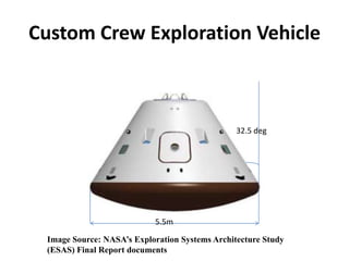
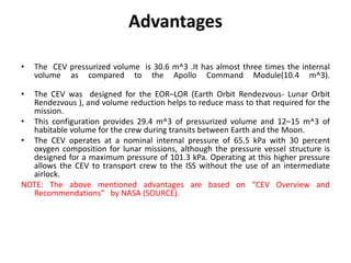
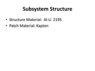
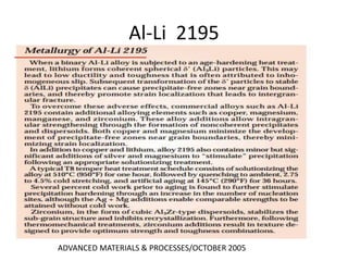
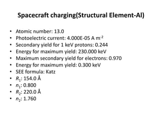
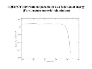
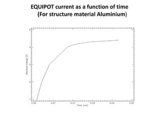
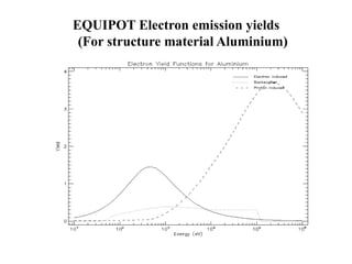

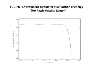
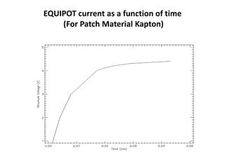
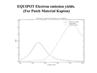
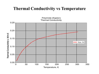
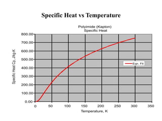
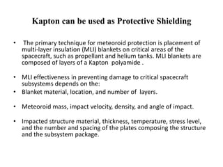
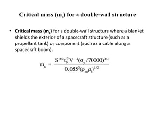
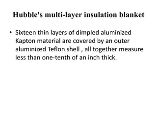
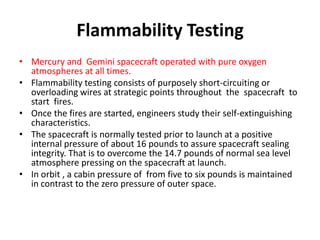
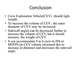

The document describes a proposed Custom Crew Exploration Vehicle (CEV) spacecraft design. It has almost three times the internal volume of the Apollo Command Module at 30.6 m^3, providing 29.4 m^3 of pressurizable volume for crew during transits. The CEV structure would use an Al-Li 2195 alloy with Kapton thermal protection. Kapton could provide meteoroid shielding due to its layered insulation design. Flammability testing of materials like Kapton was important to ensure safety for spacecraft operating with pure oxygen atmospheres.


![1012 winglee[1]](https://cdn.slidesharecdn.com/ss_thumbnails/d6vlpyl4seylo9svznet-signature-3e49a9720aafd161ec5213fc5cb0fac76e0a38578f2089fb876ad1cc6de4bad4-poli-140825181335-phpapp01-thumbnail.jpg?width=640&height=640&fit=bounds)


![1298 angel[1]](https://cdn.slidesharecdn.com/ss_thumbnails/isjwj6yosrmq2ftvlpnl-signature-fabe374f978bfb273f92443e2c8243d3e294d623a7c677008fe136d7284f57a9-poli-140825181534-phpapp01-thumbnail.jpg?width=640&height=640&fit=bounds)


![1386 voronka[1]](https://cdn.slidesharecdn.com/ss_thumbnails/qkt2almft6oweros0u9t-signature-af3363fef01d0d7c45588ce8355ebf87395936210cee8c9809ea3a5b098ac2cc-poli-140825181820-phpapp01-thumbnail.jpg?width=640&height=640&fit=bounds)
![1159 voronka[1]](https://cdn.slidesharecdn.com/ss_thumbnails/u6ur9dkkroaacb6r2m1z-signature-fabe374f978bfb273f92443e2c8243d3e294d623a7c677008fe136d7284f57a9-poli-140825181532-phpapp01-thumbnail.jpg?width=640&height=640&fit=bounds)