1) The document presents a finite element analysis of a rocket engine test bench structure conducted by researchers at PUC-Minas.
2) Static and dynamic analyses were performed using Nastran software to evaluate the structure's response to simulated engine tests. Three load scenarios were considered to account for potential misalignments.
3) The critical load case involved an applied load of 5 kN at a 5 degree angle, which produced the highest stresses and displacements. The first 20 natural frequencies of the structure were also determined.
4) The analyses found that the test bench structure would be able to withstand the expected loads from prototype engines up to 5 kN of thrust, with maximum stresses and displacements within acceptable limits
International Journal of Engineering Research and Applications (IJERA) is an open access online peer reviewed international journal that publishes research and review articles in the fields of Computer Science, Neural Networks, Electrical Engineering, Software Engineering, Information Technology, Mechanical Engineering, Chemical Engineering, Plastic Engineering, Food Technology, Textile Engineering, Nano Technology & science, Power Electronics, Electronics & Communication Engineering, Computational mathematics, Image processing, Civil Engineering, Structural Engineering, Environmental Engineering, VLSI Testing & Low Power VLSI Design etc.
Estimating damping in structure made of different m aterials (steel,brass,aluminum) and processes sti ll remains as one of the biggest challengers. All mate rials posses certain amount of internal damping,wh ich manifested as dissipation of energy from the system . This energy in a vibratory system is either dissipated into heat or radiated away from the syst em. Material damping or internal damping contribute s to about 10-15% of total system damping. Cantilever beams of required size & shape are prepared for experimental purpose & damping ratio is investigate d. Damping ratio is determined by half-power bandwidth method. It is observed that damping ratio is higher for steel than brass than aluminum.
Analysis of main beam of bridge crane based on ANSYSIJRES Journal
In this paper, the beam of bridge crane is the research object. This paper introduced the main
structure of the bridge crane. Four kinds of work conditions are studied, and a finite condition analysis is
carried out based on ANSYS. According to the actual operating results and theoretical analysis on allowable
bending and allowable stress this paper confirmed that the stiffness safety of beam meets the design
requirements, and provided reliable basis and optimization of crane design.
International Journal of Engineering and Science Invention (IJESI) is an international journal intended for professionals and researchers in all fields of computer science and electronics. IJESI publishes research articles and reviews within the whole field Engineering Science and Technology, new teaching methods, assessment, validation and the impact of new technologies and it will continue to provide information on the latest trends and developments in this ever-expanding subject. The publications of papers are selected through double peer reviewed to ensure originality, relevance, and readability. The articles published in our journal can be accessed online.
Layout Optimization of Microsatellite Components Using Genetic AlgorithmTELKOMNIKA JOURNAL
Placing the components into a container that is normally known as layout optimization problem belongs to NP-hard problems in terms of computational complexity. This study took the layout of microsatellite components as a case study to propose a basic solution strategy for the optimal layout design of a microsatellite. In this case, the layout should meet the requirements of the mission payload, the launcher and the spacecraft attitude control. It utilized the novel scheme to find the various possibilities of optimal layout using genetic algorithm combined with order-based positioning technique. Each component had a given index and then placed in a container based on specific order in accordance with a bottom-left algorithm that was already established. Meanwhile, the placement order was explored by the genetic algorithm to obtain a sequence that brought the best solution. The approach had been validated and proven to produce the optimal layout.
Analysis of Cabin Mounting Bracket of Truck Using ANSYSinventionjournals
In an automobile industry while designing the components, the most critical aspect considered is the compactness and the weight of the component. The mounting brackets are meant for supporting the structural component and electronic components such as batteries, seats, cabin, chassis, rear body and also it should support the external load such as passenger’s weight. In the initial stage the bracket is designed according to the specifications of the mountings without considering any other factors. Analysis is performed for Existing and New modified designs. The design structure is optimized for its topology and topography. In the present work an attempt has been made to produce optimized design of a mounting bracket. The modeling is carried out in CATIA and meshing with quality is ensured through Hyper Mesh. The analysis is carried out using ANSYS by the objective function as shape and topology and the weighting function as weight, and constraints are on deflection and stresses induced.
Compilation and Verification of FatigueLoad Spectrum ofHighSpeed Maglev Vehic...IJRES Journal
The purpose of this study was to construct the fatigue test load spectrum for use in the high speed
maglev vehicleswing rod.Based on the measured load spectrum of the high speed maglev vehicle running
gear,the relatively poor condition and location of the swing rod was determined, according to the statistics and
analysis the load data of swing rod. With the rain-flow cycle quantile extrapolation, a high degree confidence
load spectrum was obtained in view of the differential damage among the different tests. The eight level
one-dimensional load spectrum after mean equivalent processing was established, by applying the Goodman to
correct mean stress effect on the fatigue strength and life; The stresses under the loadswere calculated using the
ANSYSsimulation.The fatigue life obtained from the programmed load spectrum is compared with that
calculated from measured load data using Miner theory,and the accuracy and validation of the programmed
load spectrum for thehigh speed maglev vehicleswing rodwere verified.
The structural analysis is an important tool that allows the research for weight reduction, the choose of the best materials and to satisfy specifications and requirements. In an aircraft’s design, several analyzes are made to prove that this aircraft will stand the set of maneuvers that it was designed to accomplish. This work will consider the preliminar project of an aircraft seeking to check the behavior of the wing under certain loading conditions in the flight envelope.To get to this load set, it has been done all the process of specification of an aircraft, such as mission definition, calculation of weight and c.g. envelope, definition of the geometric characteristics of the aircraft, the airfoil choice, preliminary performance equations, aerodynamic coefficients and the aircraft’s balancing for the equilibrium condition, but such things will not be considered in this article. For the structural analysis of the wing will be considered an arbitrary flight condition, disregarding the effect of gusts loads. With the acquisition of the items mentioned, the main forces acting on the wing structure and their equations will be calculated. The use of finite element method will enable the application of loads obtained just as the development of a method of calculation, along with the construction of a three-dimensional model that represents a chosen condition. The results will be discussed in order to explain the influence of the applied loads in the structural behavior of the wing principal structure.
Identifying the Slider-Crank Mechanism System by the MPSO Methodijtsrd
This paper mainly proposes an efficient modified particle swarm optimization MPSO method, to identify a slider-crank mechanism driven by a field-oriented PM synchronous motor, dynamic formulations of a slider-crank mechanism have been successfully formulated with only one independent variable The parameters of many industrial machines are difficult to obtain if these machines cannot be taken apart In system identification, we adopt the MPSO method to find parameters of the slider-crank mechanism This new algorithm is added with "distance" term in the traditional PSO's fitness function to avoid converging to a local optimum It is found that the MPSO method can obtain optimal high-quality solution, high calculation efficiency, and its feasibility and effectiveness Finally, the comparisons of numerical simulations and experimental results prove that the MPSO identification method for the slider-crank mechanism is feasible Chin Wen Chuang | Kuan Yu Chen | Yi Hua Su "Identifying the Slider-Crank Mechanism System by the MPSO Method" Published in International Journal of Trend in Scientific Research and Development (ijtsrd), ISSN: 2456-6470, Volume-2 | Issue-6 , October 2018, URL: http://www.ijtsrd.com/papers/ijtsrd18413.pdf
Design, Analysis and weight optimization of Crane Hook: A Reviewijsrd.com
Crane hook are highly liable component and are always subjected to failure due to accumulation of large amount of stress which can eventually lead to its failure .In this present work, to study the different design parameter & stress pattern of crane hook in its loaded condition for different cross section, the design and drafting of crane hook will be prepared by using ANSYS 14.5. By finite element analysis, the stress which is to be formed in various cross section are compared with design calculation .The stress concentration factors are used in strength and durability evaluation of structure and machine element. In this work and also we observe the parameter that affects the weight reduction.
Comparison of stress between winkler bach theory and ansys finite element met...eSAT Journals
Abstract Crane Hooks are highly liable components and are always subjected to failure due to the amount of stresses concentration which can eventually lead to its failure. To study the stress pattern of crane hook in its loaded condition, a solid model of crane hook is prepared with the help of CATIA (Computer Aided Three Dimensional Interactive Application) software. Pattern of stress distribution in 3D model of crane hook is obtained using ANSYS software. The stress distribution pattern is verified for its correctness on model of crane hook using Winkler-Bach theory for curved beams. The complete study is an initiative to establish an ANSYS based Finite Element procedure, by validating the results, for the measurement of stress with Winkler-Bach theory for curved beams. Keywords: Crane Hook, CATIA, ANSYS, Curved Beam, Stress, Winkler-Bach Theory
OPTIMIZATION AND FATIGUE ANALYSISOF A CRANE HOOK USING FINITE ELEMENT METHODijmech
Stress analysis plays an important role in the design of structures like crane hook under loading conditions.
Crane hook is a reliable lifting component being used in industries. Structure failure of crane hook occurs
because of the stress induced due to repetitive loading and unloading conditions. In this study, solid
modeling of crane hook having trapezoidal cross-section referring to one of its existing design is done
using SOLIDWORKS. Further, analyses are carried out in ANSYS Workbench and nCode DesignLife. The
lengths of two parallel sides of the cross-section of crane hook are varied and different candidates are
obtained for loading capacity of 30 ton on the basis of Mass, total Displacement and Von-Mises stress.This
is done to reduce weight and balance economy. Further, out of these candidates, best candidates are
considered and fatigue analysis is performed on these candidates.
Model Study of Slope Stability in Open Pit by Numerical Modeling Using the Fi...CrimsonPublishersAMMS
Model Study of Slope Stability in Open Pit by Numerical Modeling Using the Finite Element Method by Saadoun Abderrazak in Aspects in Mining & Mineral Science
Mechanics of strain propogation in members of a platform structure devised fo...Dr.Vikas Deulgaonkar
This research paper deals with the mechanics of mechanical strain and its propagation in a steel structure through experimental analysis of a distinctive platform integrated with vehicle chassis. Dynamic values of strain components are evaluated on all constituents of the platform structure at various critical locations. Strain gauge classification for experimentation of the platform structure is described. Different nature of stresses at significant locations is evaluated with the aid of linear and rosette gauges.
Present-day data acquisition systems are utilized for acquiring the strain values. Static and dynamic strain values are evaluated for constant speeds on cross-country track.The experimentation reveals exact strain values, as there are no assumptions for measurement. Cross-country road characteristics are exactly simulated for this measurement process.
The optimum vehicle speed is maintained for the entire measurement process. Tri-axial values of strains are calculated using rosette reduction technique. Linear strain values are evaluated on longitudinal members of the platform structure. Values of strain acquired different locations reveal the critical areas of the structure for possible design modifications.
Applied loading and boundary condition for pre-processing of a head model of GHBMC M50.
Simulated and validated the head model against three head drop test performed by the Medical College of Wisconsin (MCW).
Energy-Efficient Driving in the Portuguese Rail Operation (MSc. Dissertation ...João Vieira
The main share of energy consumption in railways consists of traction energy, i.e., energy required to move the trains. The amount of energy consumed is much influenced by the way the train is driven within schedule. As each driver has its own driving style and since the deduction of the energy-efficient driving strategy is not trivial, there are now available Driving Advice Systems to assist drivers in choosing the most energy-efficient actions.
The aim of this study was to develop an energy-efficient driving model in order to derive, for a given route and running time, an energy-efficient speed profile. The driving model was used to build efficient driving strategies for regional and inter-regional rail services in the Douro line. The model’s energy saving potential evaluation was done by using a train-running simulator in order to compare the driver’s actions and speed profiles of real cases with the most efficient driving strategies for the same situations. The simulation results point to an energy saving potential between 11 and 15%, just by changing the driving style.
Finally, a Driver Advice System prototype was developed, in order to assist the driver in adopting an efficient driving strategy. The prototype has been developed for the Android platform, to be implemented in a low-cost equipment, such as a tablet, equipped with GPS receiver.
EShape Optimization Of A Suspension Bellcrank Using 3d Finite Element MethodsIJERA Editor
The paper represents an application of an optimization procedure for a mass and stress optimization of the bellcrank of a double wishbone suspension system of SRM University’s FormulaSAE vehicle. The used optimization procedure, so-called Fully Stressed Design, is based on an indirect approach utilizing optimum criteria. The aim of the optimization was to achieve the lowest possible mass of the construction taking into consideration the allowed resistance and also to investigate and analyze the structural stress distribution of bellcrank at the real time condition during damping process and the spring actuation.
Modify ferrari obd2 port to work with cheap $9 elm327 scannerspobd2
Most of US vehicle is designed with 16-pin diagnostic connector under the hood, while most of European vehicles are not compatible with OBD2 standard OBDII complaint. That’s properly the reason why the cheap Bluetooth or WIFI ELM327 OBD2 scan tool cannot access to Ferrari models
Pins require very little service and total failure seldom occurs. Wear, pitting, and scoring are the usual troubles
encountered with pins. In this paper, going to apply induction hardening process on pins and its comparison will
be done with existing pins. Different hardening thickness or case depth will be applied and analysis will be done
to interpret the results. Case depth of 1mm, 2mm or 2.5mm will be taken in induction hardening process.
Caterpillar 320dl excavator model is taken for study. Material used for the pins is EN8 grade of steel. And
different material used for the pin for analysis purpose will be bronze alloy, Titanium. The main objective in this
project is to determine the appropriate induction hardening case depth to be used in manufacturing pins.ThreedHiympeenrsmioensh
m aondde Alsn osfy sp iwnisl lu bseed u sined e xtoc aavnaatloyrz ew tihlle bsetr ecsres astteadtu uss oinng t hCea ptiianVs.5 T shoef tmwaarxei,m mumes hdienfgo rwmiallt iboen ,d monaex iumsuinmg
stress point and dangerous areas are found by the stress analysis.
Finite element analysis of single cylinder engineLaukik Raut
This paper deals with, the problem occurred in single cylinder engine crank shaft. It consist of static structural
and fatigue analysis of single cylinder engine crank shaft. It identifies and solves the problem by using the
modeling and simulation techniques. The topic was chosen because of increasing interest in higher payloads,
lower weight, higher efficiency and shorter load cycles in crankshaft. The main work was to model the crank
shaft with dimensions and then simulate the crank shaft for static structural and fatigue analysis. The modeling
software used is PRO-E wildfire 4.0 for modeling the crank shaft. The analysis software ANSYS will be used for
structural and fatigue analysis of crank shaft for future work. The material for crank shaft is EN9 and other
alternate materials on which analysis will be done are SAE 1045, SAE 1137, SAE 3140, and Nickel Cast Iron.
The objectives involves modeling and analysis of crank shaft, so as to identify the effect of stresses on crank
shaft, to compare various materials and to provide possible solution.
Apprioprate Boundary Condition for FEA of member isolated from global modelAun Haider
The wing of a fighter aircraft has various structural members which support aerodynamic and
inertial loads, and transmit these loads to the fuselage. As a foremost step to evaluate the structural
behaviour of the wing assembly, component contribution analysis is carried out. A finite element
analysis of wing tulip of fighter aircraft isolated from the wing was performed under the design
load case. Since aircraft wing is a statically indeterminate structure, reaction forces and moments
at the supports depend upon the stiffness characteristics of the wing itself. In addition, stiffness of
wing also affects the distribution of load and resulting deformation of the wing. These require that
support structure of tulip isolated from the global wing model is represented by appropriate boundary
conditions for the analysis. A comparative study for three boundary conditions (fixed support, nodal
displacements and elastic support) was carried out to determine the representative boundary
condition for the analysis of structural members isolated from the global model. It was found that
elastic support represents the stiffness of the global model and is a more appropriate boundary
condition for the analysis of local models which are isolated from a global model.
Optimization of Design Parameters for Crane Hook Using Finite Element AnalysisIJRTEMJOURNAL
The Crane hooks are very at risk segments that are regularly utilized for mechanical purposes.
In this way such segments in an industry must be produced and composed in an approach to convey most extreme
execution without failure. Failure of a crane hook essentially relies upon three central point i.e. measurement,
material, overload. The undertaking is worried towards expanding the safe load by fluctuating the cross-sectional
measurements of the four distinct segments and diverse materials. The chose areas are square, circle, and
trapezoidal. The territory stays consistent while changing the measurements of the four unique segments. The
crane hook is demonstrated utilizing catia programming. The pressure and life investigation is finished utilizing
ANSYS 18.1 workbench. The ordinary worry along add up to misshaping, stress and life’s according to the
materials considered. It is discovered that trapezoidal cross segment yields most extreme load of 4000 KG to 5000
KG for steady cross segment zone among four cross segment.
Design & Development of Articulated Inspection ARM for in House Inspection in...ijsrd.com
Magnetic confinement of plasma can be achieved using a device Tokamak. Concept of Tokamak confinement is also been tried to develop a fusion reactor. Reactor environment is of high hostile for human intervention due to radiation from activated atoms. For any kind of maintenance works Remote operation is necessary. An attempt was made to arrive at a concept of using articulated inspection arm to check the components if any damage or replacement required during shutdown operation of reactor machine. Proof of concept towards Design and development of articulated inspection arm for Torus Vessel was carried out & a robot having multi link joint with a camera mounted on the end point and also an arm having three degrees of freedom was attempted. The concept was materialized developing an articulated inspection robotic arm.
This paper gives description about fuel used for various spacecraft.Spacecraft propulsion is based on jet propulsion as used by rocket motors. Propulsion in a broad sense is the act of changing the motion of a body. Propulsion mechanisms provide a force that moves bodies that are initially at rest, changes a velocity, or overcomes retarding forces when a body is propelled through a medium. Jet propulsion is a means of locomotion whereby a reaction force is imparted to a device by the momentum of ejected matter. The burning rate of the solid rocket propellants is one of the most important factors that determine the performance of the rocket. The burning rate of rocket motors running with solid propellant is called flame regression, which occurs with the ignition in the fuel grain perpendicular to the burning surface. This study investigates the effects of the addition of metal-based high-energy matter (Aluminium) into the content of the propellant produced within the scope of development project. The study starts with the manufacture of propellant samples.
Contact Pressure Validation of Steam Turbine Casing for Static Loading ConditionIJMER
International Journal of Modern Engineering Research (IJMER) is Peer reviewed, online Journal. It serves as an international archival forum of scholarly research related to engineering and science education.
International Journal of Engineering Research and Applications (IJERA) is an open access online peer reviewed international journal that publishes research and review articles in the fields of Computer Science, Neural Networks, Electrical Engineering, Software Engineering, Information Technology, Mechanical Engineering, Chemical Engineering, Plastic Engineering, Food Technology, Textile Engineering, Nano Technology & science, Power Electronics, Electronics & Communication Engineering, Computational mathematics, Image processing, Civil Engineering, Structural Engineering, Environmental Engineering, VLSI Testing & Low Power VLSI Design etc.
Suitability of Composite Material for Flywheel Analysis IJMER
The paper deals with analysis of flywheel in which comparison of flywheel existing material
and test material are done. There must be proper design and analysis of flywheel in order to meet the
necessity to smooth out enormous oscillations in velocity that occur during a cycle of i.c.engine in a
flywheel. So here some finite element analysis tools are used for design and analysis purpose. Then results
are compared with existing material.
The peer-reviewed International Journal of Engineering Inventions (IJEI) is started with a mission to encourage contribution to research in Science and Technology. Encourage and motivate researchers in challenging areas of Sciences and Technology.
This paper addresses the fracture toughness ( ), or also known as critical stress intensity Factor, according to
conditions of Lineal Elastic Fracture Mechanics (LEFM). The characterization of the mechanical properties in
tensile and fracture toughness of structural steel pipes API-5L used in hydrocarbons transportation was
performed. For fracture toughness, the material was tested through fatigue crack propagation on standardized
compact specimen (CT) according to ASTM E-399 norm. A thickness (B) equal to and a crack size (a) equal
to 0.5w were used. With the porpoise of establishing the adequate conditions at the crack tip, the specimens were
subjected to fatigue pre-cracking by application of repeated cycles of load in tensile-tensile and constant load
amplitude with a load ratio of R = 0.1. The experimental Compliance method was used based on data obtained
from load vs. Crack Mouth Opening Displacement (CMOD). The results show a Stress Intensity factor of 35.88
MPa√m for a 25 mm crack size specimen. The device used for testing is a MTS-810 machine with capacity of
100KN and 6 kHz sampling rate, which meets the conditions of the ASTM E-399 standard. The cracking
susceptibility of steel is influenced by the size, morphology and distribution of non-metallic inclusions,
thermochemical interaction with the environment and microstructure.
Review: Composite Flywheel for High Speed ApplicationAM Publications
Flywheel is a device to smoothen the cyclic fluctuation of speed change when delivering constant output
power from the engine. It has no influence on the mean speed of the prime mover. It has no influence on the varying
load demand on the prime mover or the delivered power from the prime mover. In the forgoing discussion, it is
observed that turning moment diagrams for the cycle show period during which torque is in excess of the mean torque
responsible for the constant power output and also periods during which the torque is less than the mean torque. Thus
the speed of the flywheel would increase during period of excess of torque during the cycle and the speed will fall
during the period of the deficit torque during the cycle. Thus a flywheel stores energy and releases energy during the
cycle without affecting mean energy output. Thus a properly designed flywheel has to ensure the cyclic fluctuations of
speed within prescribed limits preferably as small as possible. The main objective of our project is to reduce weight of
automobile by using composite material. In this Project Work taking Flywheel as an Automobile component and
applying FEA analysis using ANSYS to optimize weight and strength of flywheel. Here Performing Analysis on metal
flywheel, carbon fiber flywheel and composite i.e. metal and carbon fiber flywheel. By using ANSYS stresses obtained
& compared with analytical calculations, also weight is compared. Composite flywheel made from steel rim & carbon
fiber body will be safe for automobile applications like F1 car. From analysis & analytical results composite flywheel
for automobile can be selected.
Engineering Science and Technology, an International Journal 2TanaMaeskm
Engineering Science and Technology, an International Journal 22 (2019) 346–352
Contents lists available at ScienceDirect
Engineering Science and Technology,
an International Journal
journal homepage: www.elsevier.com/locate/jestch
Full Length Article
Design optimization of industrial robot arm to minimize redundant
weight
https://doi.org/10.1016/j.jestch.2018.11.009
2215-0986/� 2018 Karabuk University. Publishing services by Elsevier B.V.
This is an open access article under the CC BY-NC-ND license (http://creativecommons.org/licenses/by-nc-nd/4.0/).
⇑ Corresponding author.
E-mail address: [email protected] (M. Karali).
URL: http://www.konya.edu.tr (M. Karali).
Peer review under responsibility of Karabuk University.
Mustafa Bugday, Mehmet Karali ⇑
Necmettin Erbakan University, Engineering and Architectural Faculty, Mechatronics Engineering Department, Konya, Turkey
a r t i c l e i n f o a b s t r a c t
Article history:
Received 6 January 2018
Revised 6 November 2018
Accepted 19 November 2018
Available online 8 December 2018
Keywords:
Robot arm optimization
Industrial robot
Finite element method (FEM)
In industrial robots, projected torque increases depending on the extending reach length and payload.
This requires selection of powerful motors particularly on the second axis. Since arm rigidity becomes
more important as the expected positioning precision increases, less flexible materials are used.
Therefore, during operation conditions, 70% of motor’s energy is used for redundant weight. In this study,
analyses conducted on five different robotic arms belong to different brands. Arm’s payload distribution
in terms of region and amount is examined, alternative designs are analysed and compared with each
other. Geometry and materials are changed in alternative designs. In this way, redundant weight is min-
imized (without increasing the share amount) at the same positioning precision. Results of this study
demonstrated a 10% decrease in inert payloads.
� 2018 Karabuk University. Publishing services by Elsevier B.V. This is an open access article under the CC
BY-NC-ND license (http://creativecommons.org/licenses/by-nc-nd/4.0/).
1. Introduction deformations formed on the robotic arm. From those studies, Kur-
Servomotors are used in industrial robots because of their pre-
cise positioning control and stable structures and the cost of those
motors increases in proportion with their torque. A robot with a
lifting capacity between 5 and 7 kg has about 300 kg average
weight. Especially the second axis motor carries 70–75% of the
robot’s total weight. Considering the high acceleration of robot
arms, it will be better to use a more powerful motor. Therefore,
it is important to select a different material with same strength
or to change the geometric structure of the same material to get
a reduced motor load.
There are some other studies analyzed performance or effi-
ciency of robots by employing different criteria and methods
Pupaza et al. [1] r ...
Hybrid composites have unique features that can be used to meet diverse and competing design requirements in
a more cost-effective way than either - advanced or, conventional composites. The Natural-polymer hybrid composites reinforced with carbon fiber and jute with three different orientations - 0°, 30° and 45° using epoxy resin is fabricated by hand lay-up process. The tensile test is carried out to study the tensile behavior of the developed hybrid composite.
International Journal of Engineering Research and Applications (IJERA) is an open access online peer reviewed international journal that publishes research and review articles in the fields of Computer Science, Neural Networks, Electrical Engineering, Software Engineering, Information Technology, Mechanical Engineering, Chemical Engineering, Plastic Engineering, Food Technology, Textile Engineering, Nano Technology & science, Power Electronics, Electronics & Communication Engineering, Computational mathematics, Image processing, Civil Engineering, Structural Engineering, Environmental Engineering, VLSI Testing & Low Power VLSI Design etc.
Similar to Linear Static and Dynamic Analysis of Rocket Engine Testing Bench Structure using the Finite Element Method (20)
Cosmetic shop management system project report.pdfKamal Acharya
Buying new cosmetic products is difficult. It can even be scary for those who have sensitive skin and are prone to skin trouble. The information needed to alleviate this problem is on the back of each product, but it's thought to interpret those ingredient lists unless you have a background in chemistry.
Instead of buying and hoping for the best, we can use data science to help us predict which products may be good fits for us. It includes various function programs to do the above mentioned tasks.
Data file handling has been effectively used in the program.
The automated cosmetic shop management system should deal with the automation of general workflow and administration process of the shop. The main processes of the system focus on customer's request where the system is able to search the most appropriate products and deliver it to the customers. It should help the employees to quickly identify the list of cosmetic product that have reached the minimum quantity and also keep a track of expired date for each cosmetic product. It should help the employees to find the rack number in which the product is placed.It is also Faster and more efficient way.
NO1 Uk best vashikaran specialist in delhi vashikaran baba near me online vas...Amil Baba Dawood bangali
Contact with Dawood Bhai Just call on +92322-6382012 and we'll help you. We'll solve all your problems within 12 to 24 hours and with 101% guarantee and with astrology systematic. If you want to take any personal or professional advice then also you can call us on +92322-6382012 , ONLINE LOVE PROBLEM & Other all types of Daily Life Problem's.Then CALL or WHATSAPP us on +92322-6382012 and Get all these problems solutions here by Amil Baba DAWOOD BANGALI
#vashikaranspecialist #astrologer #palmistry #amliyaat #taweez #manpasandshadi #horoscope #spiritual #lovelife #lovespell #marriagespell#aamilbabainpakistan #amilbabainkarachi #powerfullblackmagicspell #kalajadumantarspecialist #realamilbaba #AmilbabainPakistan #astrologerincanada #astrologerindubai #lovespellsmaster #kalajaduspecialist #lovespellsthatwork #aamilbabainlahore#blackmagicformarriage #aamilbaba #kalajadu #kalailam #taweez #wazifaexpert #jadumantar #vashikaranspecialist #astrologer #palmistry #amliyaat #taweez #manpasandshadi #horoscope #spiritual #lovelife #lovespell #marriagespell#aamilbabainpakistan #amilbabainkarachi #powerfullblackmagicspell #kalajadumantarspecialist #realamilbaba #AmilbabainPakistan #astrologerincanada #astrologerindubai #lovespellsmaster #kalajaduspecialist #lovespellsthatwork #aamilbabainlahore #blackmagicforlove #blackmagicformarriage #aamilbaba #kalajadu #kalailam #taweez #wazifaexpert #jadumantar #vashikaranspecialist #astrologer #palmistry #amliyaat #taweez #manpasandshadi #horoscope #spiritual #lovelife #lovespell #marriagespell#aamilbabainpakistan #amilbabainkarachi #powerfullblackmagicspell #kalajadumantarspecialist #realamilbaba #AmilbabainPakistan #astrologerincanada #astrologerindubai #lovespellsmaster #kalajaduspecialist #lovespellsthatwork #aamilbabainlahore #Amilbabainuk #amilbabainspain #amilbabaindubai #Amilbabainnorway #amilbabainkrachi #amilbabainlahore #amilbabaingujranwalan #amilbabainislamabad
Sachpazis:Terzaghi Bearing Capacity Estimation in simple terms with Calculati...Dr.Costas Sachpazis
Terzaghi's soil bearing capacity theory, developed by Karl Terzaghi, is a fundamental principle in geotechnical engineering used to determine the bearing capacity of shallow foundations. This theory provides a method to calculate the ultimate bearing capacity of soil, which is the maximum load per unit area that the soil can support without undergoing shear failure. The Calculation HTML Code included.
TECHNICAL TRAINING MANUAL GENERAL FAMILIARIZATION COURSEDuvanRamosGarzon1
AIRCRAFT GENERAL
The Single Aisle is the most advanced family aircraft in service today, with fly-by-wire flight controls.
The A318, A319, A320 and A321 are twin-engine subsonic medium range aircraft.
The family offers a choice of engines
Courier management system project report.pdfKamal Acharya
It is now-a-days very important for the people to send or receive articles like imported furniture, electronic items, gifts, business goods and the like. People depend vastly on different transport systems which mostly use the manual way of receiving and delivering the articles. There is no way to track the articles till they are received and there is no way to let the customer know what happened in transit, once he booked some articles. In such a situation, we need a system which completely computerizes the cargo activities including time to time tracking of the articles sent. This need is fulfilled by Courier Management System software which is online software for the cargo management people that enables them to receive the goods from a source and send them to a required destination and track their status from time to time.
Final project report on grocery store management system..pdfKamal Acharya
In today’s fast-changing business environment, it’s extremely important to be able to respond to client needs in the most effective and timely manner. If your customers wish to see your business online and have instant access to your products or services.
Online Grocery Store is an e-commerce website, which retails various grocery products. This project allows viewing various products available enables registered users to purchase desired products instantly using Paytm, UPI payment processor (Instant Pay) and also can place order by using Cash on Delivery (Pay Later) option. This project provides an easy access to Administrators and Managers to view orders placed using Pay Later and Instant Pay options.
In order to develop an e-commerce website, a number of Technologies must be studied and understood. These include multi-tiered architecture, server and client-side scripting techniques, implementation technologies, programming language (such as PHP, HTML, CSS, JavaScript) and MySQL relational databases. This is a project with the objective to develop a basic website where a consumer is provided with a shopping cart website and also to know about the technologies used to develop such a website.
This document will discuss each of the underlying technologies to create and implement an e- commerce website.
Forklift Classes Overview by Intella PartsIntella Parts
Discover the different forklift classes and their specific applications. Learn how to choose the right forklift for your needs to ensure safety, efficiency, and compliance in your operations.
For more technical information, visit our website https://intellaparts.com
Welcome to WIPAC Monthly the magazine brought to you by the LinkedIn Group Water Industry Process Automation & Control.
In this month's edition, along with this month's industry news to celebrate the 13 years since the group was created we have articles including
A case study of the used of Advanced Process Control at the Wastewater Treatment works at Lleida in Spain
A look back on an article on smart wastewater networks in order to see how the industry has measured up in the interim around the adoption of Digital Transformation in the Water Industry.
Hybrid optimization of pumped hydro system and solar- Engr. Abdul-Azeez.pdffxintegritypublishin
Advancements in technology unveil a myriad of electrical and electronic breakthroughs geared towards efficiently harnessing limited resources to meet human energy demands. The optimization of hybrid solar PV panels and pumped hydro energy supply systems plays a pivotal role in utilizing natural resources effectively. This initiative not only benefits humanity but also fosters environmental sustainability. The study investigated the design optimization of these hybrid systems, focusing on understanding solar radiation patterns, identifying geographical influences on solar radiation, formulating a mathematical model for system optimization, and determining the optimal configuration of PV panels and pumped hydro storage. Through a comparative analysis approach and eight weeks of data collection, the study addressed key research questions related to solar radiation patterns and optimal system design. The findings highlighted regions with heightened solar radiation levels, showcasing substantial potential for power generation and emphasizing the system's efficiency. Optimizing system design significantly boosted power generation, promoted renewable energy utilization, and enhanced energy storage capacity. The study underscored the benefits of optimizing hybrid solar PV panels and pumped hydro energy supply systems for sustainable energy usage. Optimizing the design of solar PV panels and pumped hydro energy supply systems as examined across diverse climatic conditions in a developing country, not only enhances power generation but also improves the integration of renewable energy sources and boosts energy storage capacities, particularly beneficial for less economically prosperous regions. Additionally, the study provides valuable insights for advancing energy research in economically viable areas. Recommendations included conducting site-specific assessments, utilizing advanced modeling tools, implementing regular maintenance protocols, and enhancing communication among system components.
Industrial Training at Shahjalal Fertilizer Company Limited (SFCL)MdTanvirMahtab2
This presentation is about the working procedure of Shahjalal Fertilizer Company Limited (SFCL). A Govt. owned Company of Bangladesh Chemical Industries Corporation under Ministry of Industries.
Linear Static and Dynamic Analysis of Rocket Engine Testing Bench Structure using the Finite Element Method
1. Luiza Fabrino Favato et al. Int. Journal of Engineering Research and Applications www.ijera.com
ISSN : 2248-9622, Vol. 5, Issue 4, ( Part -7) April 2015, pp.70-77
www.ijera.com 70 | P a g e
Linear Static and Dynamic Analysis of Rocket Engine Testing
Bench Structure using the Finite Element Method
Luiza Fabrino Favato*, Professor Dr. Pedro Américo Almeida Magalhães
Júnior**
*(Student of the Department of the Graduate Program in Mechanical Engineering, Pontifical Catholic
University of Minas Gerais, Brazil)
**(Member of the Department of the Graduate Program in Mechanical Engineering, Pontifical Catholic
University of Minas Gerais, Brazil)
ABSTRACT
This article presents a study of a testing bench structure for Rocket Engines, which is under development by the
PUC-Minas Aerospace Research Group. The Bench is being built for civilian’s liquid bipropellant rocket
engines up to 5 kN of thrust. The purpose of this article is to evaluate the bench structure using the Finite
Element Method (FEM), by structural linear static and dynamic analysis. Performed to predict the behavior of
the structure to the requests of the tests. The virtual simulations were performed using a CAE software with the
Nastran solver. The structure is 979 x 1638 mm by 2629 mm, consisting of folded-plates (¼ "x 3¼" x 8") and
plates of 1/4" and 1/2 ", both SAE 1020 Steel .The rocket engine is fixed on the structure through a set called
engine mount. It was included in the analysis clearances or misalignments that may occur during tests. As well
as, the load applied was evaluated with components in varying orientations and directions. It was considered the
maximum size of the engine mount and the maximum inclination angle of load. At the end of this article it was
observed that the worst stress and displacement values obtained were for the hypothesis with the inclination of
five-degrees with load components in the positive directions of the axes defined and it was also obtained the first
twenty frequency modes of the structure.
Keywords – Dynamic analysis, Finite Element Method, Linear static analysis, Rocket engine, Test bench
structure
I. INTRODUCTION
Test benches can boost research, projects and
ideas. The development of new benches can
encourage studies in several areas and consequently
development and improvement of technologies. With
increasing competition in the international market for
space access, development, construction of rockets
and associated components gain decisive importance
in the context of a country's development. The Brazil
only has the IAE's (Institute of Aeronautics and
Space) test bench for rocket propellants, which is
focused on the military sector, making it difficult for
academics and privates tests. In an effort to expand
the national aerospace activities the PUC - Minas
Aerospace Research Group initiated a project to
develop a Rocket Engine testing Bench, which
mainly will allow the measurement of several
parameters throughout the tests of rocket propellants
prototypes. Recently the project was approved as a
scientific initiation of FAPEMIG, the Foundation for
Research of the State of Minas Gerais, APQ-01369-
13 code. This article was developed to analyze the
structural integrity of the bench structure, as well as
to obtain its natural frequencies, using the finite
element method.
I.I PROBLEM
The intention of this work was to developed a
computer model that represents the impact of a test
for liquid bipropellant rocket engine prototypes, up to
5 kN of thrust. In order to observe the capability of
the structure to meet the demand safely. The problem
was modeled to absorb possible faults, which may
occur during the engine’s test procedure. It was
considered the unevenness of the propellant and the
assembly motor’s position on the structure through
the component called the engine mount. The first
natural frequency modes of the structure were
calculated for future correlation with the motor’s
driving frequencies.
I.II HYPOTHESIS
The solutions presented in this article were
obtained through considerations and hypothesis. The
considerations were made due to load’s orientation
applied on the structure and boundary conditions.
The hypothesis were presented with variation of
load’s magnitude and angle.
The refinement of the mesh was realized by
analyzing the element in view of its size's
modification and presented responses of stress and
RESEARCH ARTICLE OPEN ACCESS
2. Luiza Fabrino Favato et al. Int. Journal of Engineering Research and Applications www.ijera.com
ISSN : 2248-9622, Vol. 5, Issue 4, ( Part -7) April 2015, pp.70-77
www.ijera.com 71 | P a g e
displacements. The assembly of the engine mount
with the propellant was specified to have a maximum
length of 560 mm. The load was applied in an area
specified according to the area of a load cell, which
has a diameter of 104.8 mm.
It was used a static linear structural simulation
for three hypotheses of loading in relation to a
possible inclination of the thrust caused by the
mount’s displacement. Another possibility explored
was in order to obtain a curve variation of the
maximum Von-Mises stress for a load variation until
the worst loading condition for the structure. This
hypothesis was evaluated by exploring the behavior
of the structure to a possible fracture.
The modal analysis was performed considering
boundary conditions, analyzing the degrees of
freedom appropriated for the structure restrictions. It
was considered that the first 20 natural frequencies
are the most critical when it comes to a problem of
the resonance phenomena. As the modes of vibration
increase the energy required to occur resonance is
higher. Thus, if the engine driving frequency is equal
or closer to the natural frequency of the structure, at a
very high frequency and there is not enough energy,
the resonance phenomenon will not occur [1].
II. THEORETICAL BACKGROUND
The definition of rocket comes from Middle
Ages which is a self-sufficient projectile, that carries
its own supplies, the propellants: combustible and
oxidant. The basic principle of a rocket is simple:
matter or propellant is ejected in a high velocity,
resulting in a force reaction, the thrust [2]. The rocket
contains all propellants, being independent of the
environment and can operate in space vacuum.
Rockets can be classified by type (survey and
satellite launch vehicles); propellant (solid, liquid and
hybrid); number of stages (mono, multi-stage) and
application (manned and unmanned) [3,4]. Moreover,
rockets can have nuclear, chemical, and electrical
motors.
A test bench for rocket engines must be designed
and instrumented for determination of propellant’s
performance parameters. Some of them are engine's
thrust values, propellant's flow rate, temperature and
burning time. The bench is segmented into three main
parts, which are mechanical structure, hydraulics and
control systems [5].
III. METHODOLOGY
The adopted procedure began with literature
review, and 3D drawing of the structure and engine
mount. Then was determined the type of element and
mesh, besides the 3D drawing was simplified
creating a model shell, which it was more suitable for
the analysis. In a CAE solver Nastran software the
model was discretized and the generated mesh was
refined. With the solutions offered by the
considerations implemented, the model and the mesh
went through a refinement process.
III.I GEOMETRICAL MODEL IN 3D
The 3D drawing of the structure of the Testing
Bench for Rocket Engine of this article was
developed on 3D CAD software. The structure has
the maximum dimensions of 979 x 1638 mm by 2629
mm. It consists of folded-plates (¼"x 3 ¼" x 8") and
sheets of 1/4" and 1/2 ".
It was also conducted the drawing of engine
mount and laboratory’s outline setup project (Fig.2),
all developed by the PUC - Minas Aerospace
Research Group. The upper part of the mount has
degrees of freedom to allow the axial movement of
the engine in order to push the load cell, which is
responsible for collecting thrust values.
Figure 2 Outline of the rocket propellant laboratory
and the engine mount
III.II COMPUTATIONAL METHODOLOGY
The computational methodology used was based
on FEM, so it is segmented in determining the type of
element, developing the mathematical model,
executing the model discretization and analyzing the
results.
The discretization of the model was
accomplished by 1D elements, RBE2 and RBE3 and
2D elements, QUAD4 and TRI3, plate types, Fig.3.
The fixing screws and the engine mount were
represent by one-dimensional elements, RBE2 and
RBE3, respectively. This selection was made
because, the RBE2 is a one-dimensional element that
transfers displacement and the RBE3 transfers force
[6]. When one dimension, also called thickness, is
much smaller than the other dimensions, the plate
Guides Load Cell
Plate of 1/2"
Rocket engine
3. Luiza Fabrino Favato et al. Int. Journal of Engineering Research and Applications www.ijera.com
ISSN : 2248-9622, Vol. 5, Issue 4, ( Part -7) April 2015, pp.70-77
www.ijera.com 72 | P a g e
type element should be used. In accordance with this,
the mathematical model of the Bench's structure was
discretized using plate type elements. Moreover, a
quadrilateral element is a more complete and refined
element than the triangular element [7]. Thus, the
main element used to discretize the model was the
QUAD4. However, in almost negligible magnitude it
was also used TRI3 elements due to geometrical
difficulties Fig.3.
The finite element mesh was generated using NX
Nastran, Fig.3. This figure represents the final mesh
used for the analysis shown in this article, the
maximum size of the element was 15 mm, and it was
used 40620 QUAD4, 6 TRI3 and 11 1D elements.
The total amount of elements was 41696.
Figure 3 Isometric image of the generated mesh and
detailed view of the use of 1D and 2D elements.
Before reaching this mesh, tests were performed
and meshes were created by varying the size of
elements (5, 10 and 15 mm). As the variation of
stress values obtained was negligible and differences
offset were decreasing closer to the element size of
15 mm, this element was chosen to discretize the
model. Not only because of this, but also because the
mesh generated by a larger element, has a lower
number of elements and nodes than smaller elements,
implying in a smaller numerical error in the results.
The overall thickness of the mesh was 0.25 inches.
However, some parts of the mesh were specified with
different values of thickness because of the plates
present in the structure.
III.III LOAD HYPOTHESIS
In addition to the considerations it was assigned
three testing engine operation hypotheses, due to
hypothetical problems with the assembly, which may
cause possible gaps or misalignments. In the
hypothesis 0 it was established that during the test
there would be no problems and misalignment with
the bench structure and propellant mount assembly.
Thus, the entire load was applied on the area of load
cell. As for the other hypothesis, the load was applied
at an angle to the planes YZ and XY. To facilitate the
understanding of the assumptions Fig.4 was created.
III.IV BOUNDARY CONDITIONS – RESTRICTIONS
In Fig.5, it is indicated where the boundary
conditions were attributed to the model, which were
added to it through the central node of the elements.
The 1D RBE2 elements, in orange, represent the
screws and the nodes displayed in blue assumed the
role of the concrete.
All degrees of freedom were removed of the
elements in orange. In addition, on the elements in
blue were added translation restrictions on the X,Y
and Z axes and rotation restrictions on the X and Z
axes.
Hypothesis 0 - load applied vertically
TRI3
Element
RBE3
Element
QUAD4
Element
4. Luiza Fabrino Favato et al. Int. Journal of Engineering Research and Applications www.ijera.com
ISSN : 2248-9622, Vol. 5, Issue 4, ( Part -7) April 2015, pp.70-77
www.ijera.com 73 | P a g e
Hypothesis 1 - Load angled + Y and + Z
Hypothesis 2 - Load angled + Y and + X
Figure 4 - Hypothesis 0, 1 and 2
Figure 5 - Restriction assigned to the model
IV. RESULTS
It was initially analyzed the test results of the
mesh and the mesh results characteristics. Then the
results of the hypotheses were analyzed for the
applied load of 5 kN in three load angle variations.
Subsequently, the results of the modal analysis were
evaluated.
It is illustrated in Fig.6 the mesh details for von-
Mises stress result of the of hypothesis 1 with applied
load of 5 kN angled in five degrees. Analyzing this
mesh analytically the most critical area were in line
with the application of load on the structure in the
direction and orientation analyzed.
The results of displacements, minimum and
maximum principal stresses and von-Mises stress for
the critical hypothesis are shown in Fig.7. The overall
results of the linear static structural analysis are
shown in Fig. 8 for an applied load of 5 kN. On the 1
and 2 hypotheses the load was applied with 1, 3 and 5
degrees.
On Fig.8, it can be seen that the variation of the
displacement values hanged from 0.169 to 0.190 mm.
The minimum principal stress trend curves presented
a variation from 9.887 to 13.90 MPa. The values
obtained of the maximum principal stress were from
15.56 to 20.39 MPa. The range of values obtained for
the Von-Mises stress were very close to those
obtained for the maximum principal stress. The lower
value of the Von-Mises stress presented was 16.25
MPa and the highest was 20.43 MPa.
The critical hypothesis was the hypothesis 1 at
an angle of 5°, which presented the largest
displacement value observed of 0.190 mm and the
main minimum, maximum and von-Mises stresses of
13.90 MPa, 20.39 MPa and 20.43 MPa respectively.
The critical hypothesis was also analyzed
through the increasing of the subjected load, 5, 41
and 50 kN and it was generated the load variation
curve as a function of the von-Mises stress exposed
on Fig.9
Boundary
condition
(concrete)
Boundary
condition
(screw)
5. Luiza Fabrino Favato et al. Int. Journal of Engineering Research and Applications www.ijera.com
ISSN : 2248-9622, Vol. 5, Issue 4, ( Part -7) April 2015, pp.70-77
www.ijera.com 74 | P a g e
Figure 6 - Mesh details (Hypothesis 1-5 degrees - 5
kN - Von Mises - Structural linear static analysis)
It was also obtained the first 20 modes of natural
frequencies of the structure in Hz through the modal
analysis, Fig.10. The first mode frequency was 50.71
Hz and the 20th
was 270.5 Hz.
6. Luiza Fabrino Favato et al. Int. Journal of Engineering Research and Applications www.ijera.com
ISSN : 2248-9622, Vol. 5, Issue 4, ( Part -7) April 2015, pp.70-77
www.ijera.com 75 | P a g e
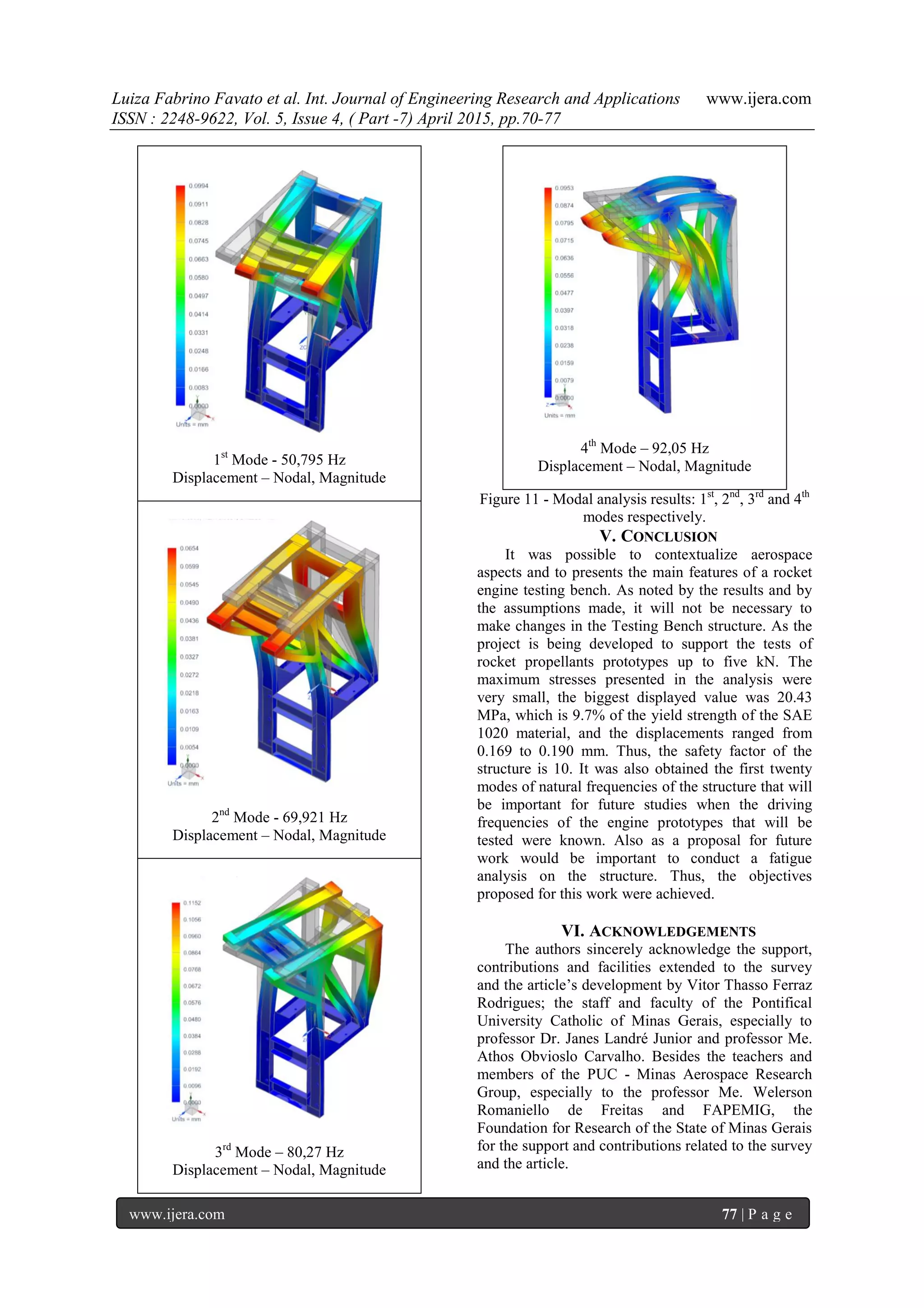
Figure 7 – Results of Hypothesis 1 - 5 kN Load – 5°
The results of the dynamic analysis are shown on
Fig.10 and 11. It was possible to observe as expected
a steady increase of the natural frequency of the
structure as it was increased the frequency modes
until the twentieth mode, Fig.10. As it is not known
the driving frequency of the rocket engines to be
tested in the Testing Bench, it is still not possible to
identify whether will may occur the resonance
phenomenon [1]. The Fig.11 illustrates the
displacements of the first four modes of natural
frequencies of the structure in mm. In general, for
most frequency modes, region in which the engine
mount is attached has the largest displacement
values.
7. Luiza Fabrino Favato et al. Int. Journal of Engineering Research and Applications www.ijera.com
ISSN : 2248-9622, Vol. 5, Issue 4, ( Part -7) April 2015, pp.70-77
www.ijera.com 76 | P a g e
Maximum displacement X angle variation - Hypothesis 0, 1 and 2
Minimum principal stress X angle variation - Hypothesis 0, 1 and 2
Figure 8 – Graphs of the overall results
Figure 9 - Graphic of von-Mises stress x variation's
load for the critic situation
Maximum principal stress X angle variation - Hypothesis 0, 1 and 2
Von-Misses stress X angle variation - Hypothesis 0, 1 and 2
The results of the dynamic analysis are shown on
Fig.10 and 11. It was possible to observe as expected
a steady increase of the natural frequency of the
structure as it was increased the frequency modes
until the twentieth mode, Fig.10. As it is not known
the driving frequency of the rocket engines to be
tested in the Testing Bench, it is still not possible to
identify whether will may occur the resonance
phenomenon [1]. The Fig.11 illustrates the
displacements of the first four modes of natural
frequencies of the structure in mm. In general, for
most frequency modes, region in which the engine
mount is attached has the largest displacement
values.
Figure 10 - Frequency Modes X Natural frequency
Von-Mises stress X load variation - Hypothesis 1 – 5 degrees
ModeFrequencies
Natural Frequencies [Hz]
0
1
2
Hypothesis Hypothesis
0
1
2
0
1
2
Hypothesis
Hypothesis
0
1
2
Von-Mises stress [MPa]
Maximum principal stress [MPa]Displacement [mm]
Minimum principal stress [MPa]
Loadapplied[N]
8. Luiza Fabrino Favato et al. Int. Journal of Engineering Research and Applications www.ijera.com
ISSN : 2248-9622, Vol. 5, Issue 4, ( Part -7) April 2015, pp.70-77
www.ijera.com 77 | P a g e
1st
Mode - 50,795 Hz
Displacement – Nodal, Magnitude
2nd
Mode - 69,921 Hz
Displacement – Nodal, Magnitude
3rd
Mode – 80,27 Hz
Displacement – Nodal, Magnitude
4th
Mode – 92,05 Hz
Displacement – Nodal, Magnitude
Figure 11 - Modal analysis results: 1st
, 2nd
, 3rd
and 4th
modes respectively.
V. CONCLUSION
It was possible to contextualize aerospace
aspects and to presents the main features of a rocket
engine testing bench. As noted by the results and by
the assumptions made, it will not be necessary to
make changes in the Testing Bench structure. As the
project is being developed to support the tests of
rocket propellants prototypes up to five kN. The
maximum stresses presented in the analysis were
very small, the biggest displayed value was 20.43
MPa, which is 9.7% of the yield strength of the SAE
1020 material, and the displacements ranged from
0.169 to 0.190 mm. Thus, the safety factor of the
structure is 10. It was also obtained the first twenty
modes of natural frequencies of the structure that will
be important for future studies when the driving
frequencies of the engine prototypes that will be
tested were known. Also as a proposal for future
work would be important to conduct a fatigue
analysis on the structure. Thus, the objectives
proposed for this work were achieved.
VI. ACKNOWLEDGEMENTS
The authors sincerely acknowledge the support,
contributions and facilities extended to the survey
and the article’s development by Vitor Thasso Ferraz
Rodrigues; the staff and faculty of the Pontifical
University Catholic of Minas Gerais, especially to
professor Dr. Janes Landré Junior and professor Me.
Athos Obvioslo Carvalho. Besides the teachers and
members of the PUC - Minas Aerospace Research
Group, especially to the professor Me. Welerson
Romaniello de Freitas and FAPEMIG, the
Foundation for Research of the State of Minas Gerais
for the support and contributions related to the survey
and the article.
9. Luiza Fabrino Favato et al. Int. Journal of Engineering Research and Applications www.ijera.com
ISSN : 2248-9622, Vol. 5, Issue 4, ( Part -7) April 2015, pp.70-77
www.ijera.com 78 | P a g e
REFERENCES
[1] D.J. Inman, Engineering vibration (Upper
Saddle River: Prentice-Hall, 2008).
[2] A.B. Van riper, Rockets and Missiles: The
Life Story of a Technology Theory
(Westport, Connecticut, London:
Greenwood Technographies, 2004).
[3] S. Nogueira, Astronáutica: ensino
fundamental e médio: Coleção explorando o
ensino (Brasília, 2009).
[4] J.W. Cornelisse, H. F. R. Schöyer, K. F.
Wakker, Rocket Propulsion and Spaceflight
Dynamics. (Pitman publishing limited,
London, 1979).
[5] R.A. Contaifer, Desenvolvimento de uma
Bancada de Testes de Propulsores Híbridos
de Baixo Empuxo, máster teses, São José
dos Campos, Instituto Nacional de Pesquisas
Espaciais, INPE, 2009.
[6] NX Nastran. Basic Dynamic Analysis,
User's Guide, 2008.
[7] H.L.S.L.S. Soriano, Método de Elementos
Finitos em Análise de Estruturas. (São
Paulo: Editora da Universidade de São
Paulo; 2003).