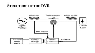
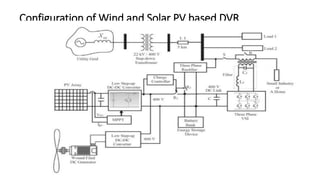
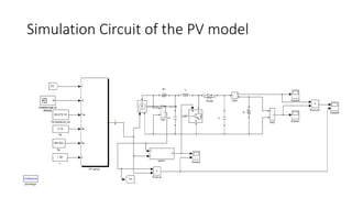
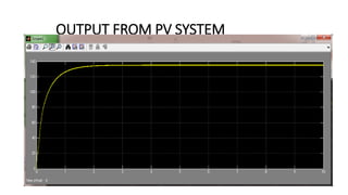
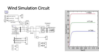
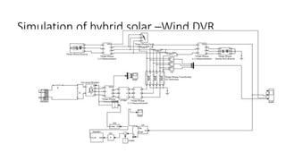
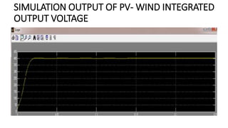
Development of a Hybrid Renewable Energy System for a Dynamic
Voltage Restorer Using Efficient Power Converters
INTRODUCTION AND OBJECTIVES OF THE WORK
• Photo voltaic based power generation is becoming a widely used in many fields as an
alternate source in place the conventional grid. One such application is DVR Dynamic
Voltage Restorer,
• DVR mitigate problems in power quality such as voltage sags, swells and outages.
• Conventional DVRs depend upon the grid for storing necessary energy that is required
for sag and swell compensation.
• The objective of this work is to use renewable energy from solar PV and wind power
through a DC-DC converter for energy required for compensation.
• The work was simulated using matlab software and the output waveforms are given.
STRUCTURE OF THE DVR
Configuration of Wind and Solar PV based DVR
Simulation results
Simulation Circuit of the PV model
PV
model
with
Boost
Converter
MAXIMUM POWER POINT FOR
VARIOUS IRRADIATIONS
CONSTANT IRRADIATION
60 WATTS
STEP IRRADIATION
37 WATTS
TRAPEZOIDAL RRADIATION
42 WATTS
OUTPUT FROM PV SYSTEM
Wind Simulation Circuit
Simulation of hybrid solar –Wind DVR
SIMULATION OUTPUT OF PV- WIND INTEGRATED
OUTPUT VOLTAGE
COMPENSATION USING PWM TECHNIQUE
• The advantage of the PWM compensation techniques used here is
to achieve better efficiency and ease of controllability.
• Combined action is possible for both the pre-sag and in-phase
compensation method.
• In this technique the system initially restores the load voltage to the
same phase and magnitude of the nominal pre-sag voltage (pre-sag
compensation) and then gradually changes the injected voltage
towards the sag voltage phasor.
• Ultimately the compensated voltage is in same magnitude and
phase angle with the pre-sag voltage and slowly its phase angle
transferred to the sagged voltage
RESPONSE OF DVR TO VOLTAGE SAG
RESPONSE OF THE DVR TO VOLTAGE SAG
AND SWELL
RESPONSE OF DVR TO POWER OUTAGE
CONCLUSION
• In this work, a Wind-solar system is utilized as source for DVR to mitigate
voltage sag and outage.
• Integrated wind-solar systems generated voltage acts as a source to the
DVR to inject the decrease in voltage when voltage sags, outages are
occurred.
• In this work control scheme based on PWM has been implemented to
control the electronic switches in the VSC used in the DVR. This PWM
control scheme only requires voltage measurements. This characteristic
makes it ideally suitable for low-voltage custom power applications.
• The simulations carried out showed that the DVR provides better voltage
regulation capabilities.
• It was also observed that the capacity for power compensation and
voltage regulation of DVR depends on the rating of the integrated wind-
solar system.
REFERENCES
[1] B. Yang, W. Li, Y. Gu, W. Cui, and X. He, “Improved transformer less inverter with common-mode leakage current elimination for a
photovoltaic grid-connected power system,” IEEE Trans. Power Electron., vol. 27,no. 2, pp. 752–762, Feb. 2012.
[2] R. Gonzalez, E. Gubia, J. Lopez, and L.Marroyo, “Transformer less single-phase multilevel-based photovoltaic inverter,” IEEE Trans.
Ind. Electron.,vol. 55, no. 7, pp. 2694–2702, Jul. 2008.
[3] H. Xiao and S. Xie, “Transformer less split-inductor neutral point clamped three-level PV grid-connected inverter,” IEEE Trans.
Power Electron.,vol. 27, no. 4, pp. 1799–1808, Apr. 2012.
[4] L. Zhang, K. Sun, L. Feng, H.Wu, and Y. Xing, “A family of neutral point clamped full-bridge topologies for transformer less
photovoltaic grid-tied inverters,” IEEE Trans. Power Electron., vol. 28, no. 2, pp. 730–739, Feb.2012.
[5] Y. Gu,W. Li,Y. Zhao, B.Yang, C. Li, and X. He, “Transformer less inverter
with virtual DC bus concept for cost-effective grid-connected PV power
systems,” IEEE Trans. Power Electron., vol. 28, no. 2, pp. 793–805, Feb.2012.
[6] S. B. Kjaer, J. K. Pederson, and F. Blaabjerg, “A review of single-phase grid-connected inverters for photovoltaic modules,” IEEE
Trans. Ind. Appl., vol. 41, no. 5, pp. 1292–1306, Sep/Oct. 2005.
[7] M. Calais, J. Myrzik, T. Spooner, and V. G. Agelidis, “Inverters for single phase grid connected photovoltaic systems—An overview,”
in Proc. IEEE PESC, 2002, vol. 2, pp. 1995–2000.
[8] Q. Li and P. Wolfs, “A review of the single phase photovoltaic module integrated converter topologies with three different dc link
configuration,”IEEE Trans. Power Electron., vol. 23, no. 3, pp. 1320–1333, May 2008.
[9] R. Gonzalez, J. Lopez, P. Sanchis, and L. Marroyo, Transformer less inverter for single-phase photovoltaic systems,” IEEE Trans.
Power Electron., vol. 22, no. 2, pp. 693–697, Mar. 2007.
[9] H. Xiao and S. Xie, “Leakage current analytical model and application in single-phase transformer less photovoltaic grid-connected
inverter,” IEEE Trans. Electromagn. Compat., vol. 52, no. 4, pp. 902–913, Nov. 2010.
[10] M. Victor, F. Greizer, S. Bremicker, and U. H¨ubler, “Method of convertinga direct current voltage from a source of direct current
voltage, more specifically from a photovoltaic source of direct current voltage, into a alternating current voltage,” U.S. Patent 7
411 802, Aug. 12,2008.
Thank You

HYBRID POWER CONVETERS- SIMULATION.pptx

  • 1.
    Development of aHybrid Renewable Energy System for a Dynamic Voltage Restorer Using Efficient Power Converters
  • 2.
    INTRODUCTION AND OBJECTIVESOF THE WORK • Photo voltaic based power generation is becoming a widely used in many fields as an alternate source in place the conventional grid. One such application is DVR Dynamic Voltage Restorer, • DVR mitigate problems in power quality such as voltage sags, swells and outages. • Conventional DVRs depend upon the grid for storing necessary energy that is required for sag and swell compensation. • The objective of this work is to use renewable energy from solar PV and wind power through a DC-DC converter for energy required for compensation. • The work was simulated using matlab software and the output waveforms are given.
  • 3.
  • 4.
    Configuration of Windand Solar PV based DVR
  • 5.
  • 6.
  • 7.
  • 8.
    MAXIMUM POWER POINTFOR VARIOUS IRRADIATIONS CONSTANT IRRADIATION 60 WATTS STEP IRRADIATION 37 WATTS TRAPEZOIDAL RRADIATION 42 WATTS
  • 9.
  • 10.
  • 11.
    Simulation of hybridsolar –Wind DVR
  • 12.
    SIMULATION OUTPUT OFPV- WIND INTEGRATED OUTPUT VOLTAGE
  • 13.
    COMPENSATION USING PWMTECHNIQUE • The advantage of the PWM compensation techniques used here is to achieve better efficiency and ease of controllability. • Combined action is possible for both the pre-sag and in-phase compensation method. • In this technique the system initially restores the load voltage to the same phase and magnitude of the nominal pre-sag voltage (pre-sag compensation) and then gradually changes the injected voltage towards the sag voltage phasor. • Ultimately the compensated voltage is in same magnitude and phase angle with the pre-sag voltage and slowly its phase angle transferred to the sagged voltage
  • 14.
    RESPONSE OF DVRTO VOLTAGE SAG
  • 15.
    RESPONSE OF THEDVR TO VOLTAGE SAG AND SWELL
  • 16.
    RESPONSE OF DVRTO POWER OUTAGE
  • 17.
    CONCLUSION • In thiswork, a Wind-solar system is utilized as source for DVR to mitigate voltage sag and outage. • Integrated wind-solar systems generated voltage acts as a source to the DVR to inject the decrease in voltage when voltage sags, outages are occurred. • In this work control scheme based on PWM has been implemented to control the electronic switches in the VSC used in the DVR. This PWM control scheme only requires voltage measurements. This characteristic makes it ideally suitable for low-voltage custom power applications. • The simulations carried out showed that the DVR provides better voltage regulation capabilities. • It was also observed that the capacity for power compensation and voltage regulation of DVR depends on the rating of the integrated wind- solar system.
  • 18.
    REFERENCES [1] B. Yang,W. Li, Y. Gu, W. Cui, and X. He, “Improved transformer less inverter with common-mode leakage current elimination for a photovoltaic grid-connected power system,” IEEE Trans. Power Electron., vol. 27,no. 2, pp. 752–762, Feb. 2012. [2] R. Gonzalez, E. Gubia, J. Lopez, and L.Marroyo, “Transformer less single-phase multilevel-based photovoltaic inverter,” IEEE Trans. Ind. Electron.,vol. 55, no. 7, pp. 2694–2702, Jul. 2008. [3] H. Xiao and S. Xie, “Transformer less split-inductor neutral point clamped three-level PV grid-connected inverter,” IEEE Trans. Power Electron.,vol. 27, no. 4, pp. 1799–1808, Apr. 2012. [4] L. Zhang, K. Sun, L. Feng, H.Wu, and Y. Xing, “A family of neutral point clamped full-bridge topologies for transformer less photovoltaic grid-tied inverters,” IEEE Trans. Power Electron., vol. 28, no. 2, pp. 730–739, Feb.2012. [5] Y. Gu,W. Li,Y. Zhao, B.Yang, C. Li, and X. He, “Transformer less inverter with virtual DC bus concept for cost-effective grid-connected PV power systems,” IEEE Trans. Power Electron., vol. 28, no. 2, pp. 793–805, Feb.2012. [6] S. B. Kjaer, J. K. Pederson, and F. Blaabjerg, “A review of single-phase grid-connected inverters for photovoltaic modules,” IEEE Trans. Ind. Appl., vol. 41, no. 5, pp. 1292–1306, Sep/Oct. 2005. [7] M. Calais, J. Myrzik, T. Spooner, and V. G. Agelidis, “Inverters for single phase grid connected photovoltaic systems—An overview,” in Proc. IEEE PESC, 2002, vol. 2, pp. 1995–2000. [8] Q. Li and P. Wolfs, “A review of the single phase photovoltaic module integrated converter topologies with three different dc link configuration,”IEEE Trans. Power Electron., vol. 23, no. 3, pp. 1320–1333, May 2008. [9] R. Gonzalez, J. Lopez, P. Sanchis, and L. Marroyo, Transformer less inverter for single-phase photovoltaic systems,” IEEE Trans. Power Electron., vol. 22, no. 2, pp. 693–697, Mar. 2007. [9] H. Xiao and S. Xie, “Leakage current analytical model and application in single-phase transformer less photovoltaic grid-connected inverter,” IEEE Trans. Electromagn. Compat., vol. 52, no. 4, pp. 902–913, Nov. 2010. [10] M. Victor, F. Greizer, S. Bremicker, and U. H¨ubler, “Method of convertinga direct current voltage from a source of direct current voltage, more specifically from a photovoltaic source of direct current voltage, into a alternating current voltage,” U.S. Patent 7 411 802, Aug. 12,2008.
  • 19.