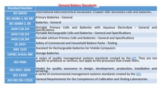
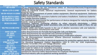
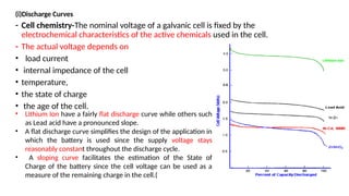
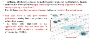
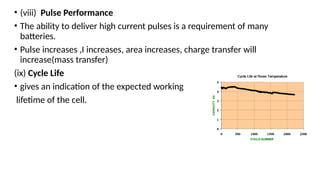
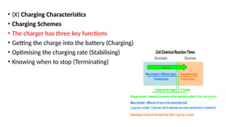
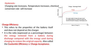
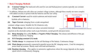
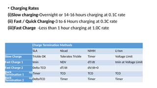
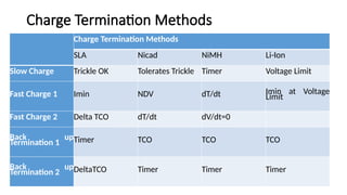
Battery standards
Standard Number Title
IEC 60050 International electrotechnical vocabulary. Chapter 486: Secondary cells and batteries.
IEC 60086-1, BS 387 Primary Batteries - General
IEC 60086-2, BS Batteries - General
ANSI C18.1M Portable Primary Cells and Batteries with Aqueous Electrolyte - General and
Specifications
ANSI C18.2M Portable Rechargeable Cells and Batteries - General and Specifications
ANSI C18.3M Portable Lithium Primary Cells and Batteries - General and Specifications
UL 2054 Safety of Commercial and Household Battery Packs - Testing
IEEE 1625 Standard for Rechargeable Batteries for Mobile Computers
USNEC Article 480 Storage Batteries
ISO 9000
A series of quality management systems standards created by the ISO. They are not
specific to products or services, but apply to the processes that create them.
ISO 9001: 2000 Model for quality assurance in design, development, production, installation and
servicing.
ISO 14000 A series of environmental management systems standards created by the ISO.
ISO/IEC/EN 17025 General Requirements for the Competence of Calibration and Testing Laboratories
General Battery Standards
Safety Standards
Standard Number Title
IEC 61508 The IEC requirements for the functional safety of Electrical/Electronic/Programmable
Electronic Safety Related Systems
BS EN 1175-1:1998 Safety of industrial trucks. Electrical requirements. General requirements for battery
powered trucks
BS EN 45510-2-3:2000 Guide for the procurement of power station equipment. Electrical equipment. Stationary
batteries and chargers
BS EN 50272-2:2001 Safety requirements for secondary batteries and battery installations. Stationary batteries
BS EN60950-1: 2002 Low Voltage Directive (Safety)
IEC/TR2 61430:1997 Test methods for determining the performance of devices designed for reducing explosion
hazards - Lead-acid batteries
IEC62133:2002 Secondary batteries containing alkaline or other non-acid electrolytes - Safety
requirements for portable sealed secondary cells, and for batteries made of them, for use
in portable applications
IEC/TR2 61438:1996 Possible safety and health hazards in the use of alkaline secondary cells and batteries -
Guide to equipment manufacturers and users
ANSI C18.2M Safety Requirements for Portable Rechargeable Cells and Batteries
UL 2054 Safety Requirements for Household and Commercial Batteries
EN 45011 General requirements for bodies operating product certification schemes
EAS The UK Electrotechnical Assessment Scheme (Electrical installation safety standards
managed by the IEE)
BS 2754 Memorandum. Construction of electrical equipment for protection against electric shock
STRD Low Voltage
Directive
The Electrical Equipment (Safety) Regulations 1994 SI 1994 No. 3260 Implementing
Directive 73/23/EEC (The Low Voltage Directive - LVD)
IEC 479-1 Effects of current on human beings and livestock
IEEE 80 2000 IEEE Guide for Safety in AC Substation Grounding
HSG 85 HSE publication. Electricity at Work. Safe Working Practices
NFPA 70E-1995 Standard for Electrical Safety Requirements for Employee Workplaces
OSHA - 29 CFR 1910, Electrical industry safe occupational working standards
Battery Performance Characteristics
• Battery must be
• Long Life, High Capacity, High Energy, Deep Cycle, Heavy Duty, Fast
Charge, Quick Charge, Ultra etc.
• Apart from the basic battery design,
• performance actually depends on how the batteries are used and
also on the environmental conditions under which they are used
(i)Discharge Curves
- Cell chemistry-The nominal voltage of a galvanic cell is fixed by the
electrochemical characteristics of the active chemicals used in the cell.
- The actual voltage depends on
• load current
• internal impedance of the cell
• temperature,
• the state of charge
• the age of the cell.
• Lithium Ion have a fairly flat discharge curve while others such
as Lead acid have a pronounced slope.
• A flat discharge curve simplifies the design of the application in
which the battery is used since the supply voltage stays
reasonably constant throughout the discharge cycle.
• A sloping curve facilitates the estimation of the State of
Charge of the battery since the cell voltage can be used as a
measure of the remaining charge in the cell.(
• (ii) Temperature Characteristics
• Cell performance can change dramatically with temperature
• At the lower extreme, the electrolyte itself may freeze
• At low temperatures , Lithium plating of the anode causing a
permanent reduction in capacity.
• At the upper extreme the active chemicals
may break down destroying the battery
• (iii) Self Discharge Characteristics
• The self discharge rate is a measure of how quickly a cell will lose its energy while
sitting on the shelf due to unwanted chemical actions within the cell.
• The rate depends on the cell chemistry and the temperature.
• Cell Chemistry Temperature Effects
• The typical shelf life forsome primary cells:
• Zinc Carbon (Leclanché) 2 to 3 years
• Alkaline 5 years
• Lithium 10 years or more
• Typical self discharge rates for common
• rechargeable cells are as follows:
• Lead Acid 4% to 6% per month
• Nickel Cadmium 15% to 20% per month
• Nickel Metal Hydride 30% per month
• Lithium 2% to 3% per month
• The rate of unwanted chemical reactions which
cause internal current leakage between the
positive and negative electrodes of the cell, like all
chemical reactions, increases with temperature
thus increasing the battery self discharge rate
• (iv) Internal Impedance(milliohms)
• The internal impedance of a cell determines its current carrying capability.
• A low internal resistance allows high currents
• Effects of Internal Impedance
 I increases, Voltage drop across Zint increases, Terminal
voltage decreases during discharge, voltage needed to charge the cell increases,
reducing its effective capacity as well as decreasing its charge/discharge efficiency.
the smaller the granular size of the electrolyte
material the lower the impedance.
The internal resistance of a galvanic cell is temperature
dependent, decreasing as the temperature rises due
to the increase in electron mobility, but efficiency
Increases.
Low Zint ,self discharge rate increases, capacity decreases.
• Some form of heating and cooling may be required to maintain the
cell within a restricted temperature range to achieve the optimum
performance in high power applications.
• Cell ages, the internal impedance increases.
• (v)Discharge Rate
• the effective capacity of the cell is reduced if the cell is discharged at
very high rates (vi) Battery Load
Battery discharge performance depends on the load the battery has to
supply
(vii)Duty Cycle
• Duty cycles are different for each application. EV and HEV applications
impose particular, variable loads on the battery.
Peukert Equation (C = In
T )(
• The Peukert equation is a convenient way of characterising
cell behaviour and of quantifying the capacity offset in
mathematical terms
• The effective battery capacity is reduced at
very high continuous discharge rates.
• With intermittent use the battery
has time to recover during quiescent periods
when the temperature will also return towards the ambient level.
• Because of this potential for recovery, the capacity reduction is less and the
operating efficiency is greater if the battery is used intermittently e
• The equation shows that at higher currents, there is less available
energy in the battery.
• The Peukert Number is directly related to the internal resistance of
the battery. Higher currents mean more losses and less available
capacity.
• Ragone Plots
• The Ragone plot is useful for characterising the trade-off between effective
capacity and power handling.
• The graph below shows the superior
gravimetric energy density of Lithium
Ion cells.
• deliver a very high power density
but a reduced energy density.
• The Ragone plot below compares the performance of a range of electrochemical devices.
• It shows that ultra capacitors (super capacitors) can deliver very high power but the
storage capacity is very limited.
• Fuel Cells can store large amounts of energy but have a relatively low power output
• fuel cells have a very poor dynamic
performance taking hours to generate and
deliver their energy.
• This limits their application in EV
applications where they are often used in
conjunction with batteries or capacitors to
overcome this problem
• (viii) Pulse Performance
• The ability to deliver high current pulses is a requirement of many
batteries.
• Pulse increases ,I increases, area increases, charge transfer will
increase(mass transfer)
(ix) Cycle Life
• gives an indication of the expected working
lifetime of the cell.
• Total Energy Throughput(Lifetime Energy Throughput)
• A more representative measure of battery life
• The total amount of energy in Watthours which can be put into and
taken out of a battery over all the cycles in its lifetime before its
capacity reduces to 80% of its initial capacity when new.
• depends on the cell chemistry and the operating conditions
• (X) Charging Characteristics
• Charging Schemes
• The charger has three key functions
• Getting the charge into the battery (Charging)
• Optimising the charging rate (Stabilising)
• Knowing when to stop (Terminating)
Hysteresis:
Charging rate increases, Temperature increases, chemical
conversion rate will increase
Charge Efficiency
• This refers to the properties of the battery itself
and does not depend on the charger.
• It is the ratio (expressed as a percentage) between
the energy removed from a battery during
discharge compared with the energy used during
charging to restore the original capacity. Also called
the Coulombic Efficiency or Charge Acceptance.
• Basic Charging Methods
(i) Constant Voltage-The lead-acid cells used for cars and backup power systems typically use constant
voltage chargers.
• In addition, lithium-ion cells often use constant voltage systems, although these usually are more complex
with added circuitry to protect both the batteries and the user safety
(i) Constant Current -used for nickel-cadmium and nickel-metal
hydride cells or batteries.
(ii) Taper Current -charging from a crude unregulated
constant voltage source, Suitable for SLA batteries only.
(iii) Pulsed charge -this method can reduce unwanted chemical
reactions at the electrode surface such as gas formation, crystal growth and passivation.
(iv) Burp charging Also called Reflex or Negative Pulse Charging -The release and diffusion of the gas
bubbles is known as "burping
(v) IUI Charging-constant I,V,I mode
(vi) Trickle charge -to compensate for the self discharge of the battery. Continuous charge.
(vii) Float charge-permanently connected in parallel across the DC charging source , Used for emergency
power back up systems. Mainly used with lead acid batteries.
(viii) Random charging -This applies to automotive applications where the energy depends on the engine
speed which is continuously changing.
• Charging Rates
(i)Slow charging-Overnight or 14-16 hours charging at 0.1C rate
(ii) Fast / Quick Charging-3 to 6 Hours charging at 0.3C rate
(iii)Fast Charge -Less than 1 hour charging at 1.0C rate
Charge Termination Methods
SLA Nicad NiMH Li-Ion
Slow Charge Trickle OK Tolerates Trickle Timer Voltage Limit
Fast Charge 1 Imin NDV dT/dt Imin at Voltage Limit
Fast Charge 2 Delta TCO dT/dt dV/dt=0
Back up
Termination 1 Timer TCO TCO TCO
Back up
Termination 2 DeltaTCO Timer Timer Timer
Charge Termination Methods
SLA Nicad NiMH Li-Ion
Slow Charge Trickle OK Tolerates Trickle Timer Voltage Limit
Fast Charge 1 Imin NDV dT/dt Imin at Voltage
Limit
Fast Charge 2 Delta TCO dT/dt dV/dt=0
Back up
Termination 1 Timer TCO TCO TCO
Back up
Termination 2 DeltaTCO Timer Timer Timer
• Charge Control Methods
• Regular (slow) charge
• Semi constant current
• Timer controlled charge system
Battery Safety
• Batteries have the potential to be dangerous if they are not carefully
designed or if they are abused.
• pack manufacturers incorporate safety devices into the pack designs
to protect the battery from out of tolerance operating conditions and
where possible from abuse.
• Once the battery has left the factory its fate is in the hands of the
user. It is usual to provide "Instructions For Use" with battery products
which alert the end user to potential dangers from abuse of the
battery
• Multi Level Battery Safety Plan
• The responsibility for battery safety starts at the cell maker's premises and
continues through to the design of the battery application. A multi-level safety
plan should include consideration of at least the following components.
• Begin with intrinsically safe cell chemistry
• Designed in safety measures
• Supplier and production audit
• Cell design audit
• Manufacturer's technical capability
• Staff (Engineering, Management)
• Facilities (Materials analysis capability)
• Manufacturer's quality systems.
• Process controls. (In place and being implemented)
• Cell level safety devices
• CID (Circuit Interrupt Device),Shut down separator, Pressure vent
• External circuit devices
• PTC resistors (Low power only)
• Fuses
• Cell and battery isolation to prevent event propagation
• Electrical (Contactors)
• Physical (Separation, barriers)
• BMS Software
• Monitoring of all key indicators coupled to control actions.
• (Cooling, Power disconnect)
• BMS Hardware
• Fail safe back-up hardware switch off in case of software failure. Set to slightly higher limits
than the software controls.
• Battery switch off in case the low voltage BMS power supply or other system component
fails.
• Containment
• Use multiple low capacity cells which release less energy in case of an event.
• Design in physical barriers to heat and flame propagation between cells.
• Designed in safety measures
• Cell chemistry -using a less reactive chemical mix , by introducing some form of chemical
retardant in order to reduce the risk of fire
• Electrolytes-Chemical inhibitors are added
• Cell construction -high power cells however, thermal design can be a source of weakness.
• Separators-Rigid separators , Flexible ceramic powder coated , Shut down separators
• Robust packaging
• Circuit Interrupt Device (CID)-which interrupts the current if the internal gas pressure in
the cell exceeds specified limits.
• PTC (Pressure, Temperature, Current) Switch -A slightly more complex safety device
which inhibits current surges and interrupts the circuit in case of excess pressure or over
temperature
• Safety vents -Safety vents are needed as a final safety precaution to release the pressure
before it reaches a dangerous level
• Keyed and shrouded connectors or terminals -to protect the operator, to prevent
accidental short circuits and the connection of incorrect loads or chargers to the battery.
Battery standards- ENERGY STORAGE SYSTEMSpptx

Battery standards- ENERGY STORAGE SYSTEMSpptx

  • 1.
  • 2.
    Standard Number Title IEC60050 International electrotechnical vocabulary. Chapter 486: Secondary cells and batteries. IEC 60086-1, BS 387 Primary Batteries - General IEC 60086-2, BS Batteries - General ANSI C18.1M Portable Primary Cells and Batteries with Aqueous Electrolyte - General and Specifications ANSI C18.2M Portable Rechargeable Cells and Batteries - General and Specifications ANSI C18.3M Portable Lithium Primary Cells and Batteries - General and Specifications UL 2054 Safety of Commercial and Household Battery Packs - Testing IEEE 1625 Standard for Rechargeable Batteries for Mobile Computers USNEC Article 480 Storage Batteries ISO 9000 A series of quality management systems standards created by the ISO. They are not specific to products or services, but apply to the processes that create them. ISO 9001: 2000 Model for quality assurance in design, development, production, installation and servicing. ISO 14000 A series of environmental management systems standards created by the ISO. ISO/IEC/EN 17025 General Requirements for the Competence of Calibration and Testing Laboratories General Battery Standards
  • 3.
    Safety Standards Standard NumberTitle IEC 61508 The IEC requirements for the functional safety of Electrical/Electronic/Programmable Electronic Safety Related Systems BS EN 1175-1:1998 Safety of industrial trucks. Electrical requirements. General requirements for battery powered trucks BS EN 45510-2-3:2000 Guide for the procurement of power station equipment. Electrical equipment. Stationary batteries and chargers BS EN 50272-2:2001 Safety requirements for secondary batteries and battery installations. Stationary batteries BS EN60950-1: 2002 Low Voltage Directive (Safety) IEC/TR2 61430:1997 Test methods for determining the performance of devices designed for reducing explosion hazards - Lead-acid batteries IEC62133:2002 Secondary batteries containing alkaline or other non-acid electrolytes - Safety requirements for portable sealed secondary cells, and for batteries made of them, for use in portable applications IEC/TR2 61438:1996 Possible safety and health hazards in the use of alkaline secondary cells and batteries - Guide to equipment manufacturers and users ANSI C18.2M Safety Requirements for Portable Rechargeable Cells and Batteries UL 2054 Safety Requirements for Household and Commercial Batteries EN 45011 General requirements for bodies operating product certification schemes EAS The UK Electrotechnical Assessment Scheme (Electrical installation safety standards managed by the IEE) BS 2754 Memorandum. Construction of electrical equipment for protection against electric shock STRD Low Voltage Directive The Electrical Equipment (Safety) Regulations 1994 SI 1994 No. 3260 Implementing Directive 73/23/EEC (The Low Voltage Directive - LVD) IEC 479-1 Effects of current on human beings and livestock IEEE 80 2000 IEEE Guide for Safety in AC Substation Grounding HSG 85 HSE publication. Electricity at Work. Safe Working Practices NFPA 70E-1995 Standard for Electrical Safety Requirements for Employee Workplaces OSHA - 29 CFR 1910, Electrical industry safe occupational working standards
  • 4.
    Battery Performance Characteristics •Battery must be • Long Life, High Capacity, High Energy, Deep Cycle, Heavy Duty, Fast Charge, Quick Charge, Ultra etc. • Apart from the basic battery design, • performance actually depends on how the batteries are used and also on the environmental conditions under which they are used
  • 5.
    (i)Discharge Curves - Cellchemistry-The nominal voltage of a galvanic cell is fixed by the electrochemical characteristics of the active chemicals used in the cell. - The actual voltage depends on • load current • internal impedance of the cell • temperature, • the state of charge • the age of the cell. • Lithium Ion have a fairly flat discharge curve while others such as Lead acid have a pronounced slope. • A flat discharge curve simplifies the design of the application in which the battery is used since the supply voltage stays reasonably constant throughout the discharge cycle. • A sloping curve facilitates the estimation of the State of Charge of the battery since the cell voltage can be used as a measure of the remaining charge in the cell.(
  • 6.
    • (ii) TemperatureCharacteristics • Cell performance can change dramatically with temperature • At the lower extreme, the electrolyte itself may freeze • At low temperatures , Lithium plating of the anode causing a permanent reduction in capacity. • At the upper extreme the active chemicals may break down destroying the battery
  • 7.
    • (iii) SelfDischarge Characteristics • The self discharge rate is a measure of how quickly a cell will lose its energy while sitting on the shelf due to unwanted chemical actions within the cell. • The rate depends on the cell chemistry and the temperature. • Cell Chemistry Temperature Effects • The typical shelf life forsome primary cells: • Zinc Carbon (Leclanché) 2 to 3 years • Alkaline 5 years • Lithium 10 years or more • Typical self discharge rates for common • rechargeable cells are as follows: • Lead Acid 4% to 6% per month • Nickel Cadmium 15% to 20% per month • Nickel Metal Hydride 30% per month • Lithium 2% to 3% per month • The rate of unwanted chemical reactions which cause internal current leakage between the positive and negative electrodes of the cell, like all chemical reactions, increases with temperature thus increasing the battery self discharge rate
  • 8.
    • (iv) InternalImpedance(milliohms) • The internal impedance of a cell determines its current carrying capability. • A low internal resistance allows high currents • Effects of Internal Impedance  I increases, Voltage drop across Zint increases, Terminal voltage decreases during discharge, voltage needed to charge the cell increases, reducing its effective capacity as well as decreasing its charge/discharge efficiency. the smaller the granular size of the electrolyte material the lower the impedance. The internal resistance of a galvanic cell is temperature dependent, decreasing as the temperature rises due to the increase in electron mobility, but efficiency Increases. Low Zint ,self discharge rate increases, capacity decreases.
  • 9.
    • Some formof heating and cooling may be required to maintain the cell within a restricted temperature range to achieve the optimum performance in high power applications. • Cell ages, the internal impedance increases.
  • 10.
    • (v)Discharge Rate •the effective capacity of the cell is reduced if the cell is discharged at very high rates (vi) Battery Load Battery discharge performance depends on the load the battery has to supply
  • 11.
    (vii)Duty Cycle • Dutycycles are different for each application. EV and HEV applications impose particular, variable loads on the battery. Peukert Equation (C = In T )( • The Peukert equation is a convenient way of characterising cell behaviour and of quantifying the capacity offset in mathematical terms • The effective battery capacity is reduced at very high continuous discharge rates. • With intermittent use the battery has time to recover during quiescent periods when the temperature will also return towards the ambient level. • Because of this potential for recovery, the capacity reduction is less and the operating efficiency is greater if the battery is used intermittently e
  • 12.
    • The equationshows that at higher currents, there is less available energy in the battery. • The Peukert Number is directly related to the internal resistance of the battery. Higher currents mean more losses and less available capacity.
  • 13.
    • Ragone Plots •The Ragone plot is useful for characterising the trade-off between effective capacity and power handling. • The graph below shows the superior gravimetric energy density of Lithium Ion cells. • deliver a very high power density but a reduced energy density.
  • 14.
    • The Ragoneplot below compares the performance of a range of electrochemical devices. • It shows that ultra capacitors (super capacitors) can deliver very high power but the storage capacity is very limited. • Fuel Cells can store large amounts of energy but have a relatively low power output • fuel cells have a very poor dynamic performance taking hours to generate and deliver their energy. • This limits their application in EV applications where they are often used in conjunction with batteries or capacitors to overcome this problem
  • 15.
    • (viii) PulsePerformance • The ability to deliver high current pulses is a requirement of many batteries. • Pulse increases ,I increases, area increases, charge transfer will increase(mass transfer) (ix) Cycle Life • gives an indication of the expected working lifetime of the cell.
  • 16.
    • Total EnergyThroughput(Lifetime Energy Throughput) • A more representative measure of battery life • The total amount of energy in Watthours which can be put into and taken out of a battery over all the cycles in its lifetime before its capacity reduces to 80% of its initial capacity when new. • depends on the cell chemistry and the operating conditions
  • 17.
    • (X) ChargingCharacteristics • Charging Schemes • The charger has three key functions • Getting the charge into the battery (Charging) • Optimising the charging rate (Stabilising) • Knowing when to stop (Terminating)
  • 18.
    Hysteresis: Charging rate increases,Temperature increases, chemical conversion rate will increase Charge Efficiency • This refers to the properties of the battery itself and does not depend on the charger. • It is the ratio (expressed as a percentage) between the energy removed from a battery during discharge compared with the energy used during charging to restore the original capacity. Also called the Coulombic Efficiency or Charge Acceptance.
  • 19.
    • Basic ChargingMethods (i) Constant Voltage-The lead-acid cells used for cars and backup power systems typically use constant voltage chargers. • In addition, lithium-ion cells often use constant voltage systems, although these usually are more complex with added circuitry to protect both the batteries and the user safety (i) Constant Current -used for nickel-cadmium and nickel-metal hydride cells or batteries. (ii) Taper Current -charging from a crude unregulated constant voltage source, Suitable for SLA batteries only. (iii) Pulsed charge -this method can reduce unwanted chemical reactions at the electrode surface such as gas formation, crystal growth and passivation. (iv) Burp charging Also called Reflex or Negative Pulse Charging -The release and diffusion of the gas bubbles is known as "burping (v) IUI Charging-constant I,V,I mode (vi) Trickle charge -to compensate for the self discharge of the battery. Continuous charge. (vii) Float charge-permanently connected in parallel across the DC charging source , Used for emergency power back up systems. Mainly used with lead acid batteries. (viii) Random charging -This applies to automotive applications where the energy depends on the engine speed which is continuously changing.
  • 20.
    • Charging Rates (i)Slowcharging-Overnight or 14-16 hours charging at 0.1C rate (ii) Fast / Quick Charging-3 to 6 Hours charging at 0.3C rate (iii)Fast Charge -Less than 1 hour charging at 1.0C rate Charge Termination Methods SLA Nicad NiMH Li-Ion Slow Charge Trickle OK Tolerates Trickle Timer Voltage Limit Fast Charge 1 Imin NDV dT/dt Imin at Voltage Limit Fast Charge 2 Delta TCO dT/dt dV/dt=0 Back up Termination 1 Timer TCO TCO TCO Back up Termination 2 DeltaTCO Timer Timer Timer
  • 21.
    Charge Termination Methods ChargeTermination Methods SLA Nicad NiMH Li-Ion Slow Charge Trickle OK Tolerates Trickle Timer Voltage Limit Fast Charge 1 Imin NDV dT/dt Imin at Voltage Limit Fast Charge 2 Delta TCO dT/dt dV/dt=0 Back up Termination 1 Timer TCO TCO TCO Back up Termination 2 DeltaTCO Timer Timer Timer
  • 22.
    • Charge ControlMethods • Regular (slow) charge • Semi constant current • Timer controlled charge system
  • 23.
    Battery Safety • Batterieshave the potential to be dangerous if they are not carefully designed or if they are abused. • pack manufacturers incorporate safety devices into the pack designs to protect the battery from out of tolerance operating conditions and where possible from abuse. • Once the battery has left the factory its fate is in the hands of the user. It is usual to provide "Instructions For Use" with battery products which alert the end user to potential dangers from abuse of the battery
  • 24.
    • Multi LevelBattery Safety Plan • The responsibility for battery safety starts at the cell maker's premises and continues through to the design of the battery application. A multi-level safety plan should include consideration of at least the following components. • Begin with intrinsically safe cell chemistry • Designed in safety measures • Supplier and production audit • Cell design audit • Manufacturer's technical capability • Staff (Engineering, Management) • Facilities (Materials analysis capability) • Manufacturer's quality systems. • Process controls. (In place and being implemented) • Cell level safety devices • CID (Circuit Interrupt Device),Shut down separator, Pressure vent
  • 25.
    • External circuitdevices • PTC resistors (Low power only) • Fuses • Cell and battery isolation to prevent event propagation • Electrical (Contactors) • Physical (Separation, barriers) • BMS Software • Monitoring of all key indicators coupled to control actions. • (Cooling, Power disconnect) • BMS Hardware • Fail safe back-up hardware switch off in case of software failure. Set to slightly higher limits than the software controls. • Battery switch off in case the low voltage BMS power supply or other system component fails. • Containment • Use multiple low capacity cells which release less energy in case of an event. • Design in physical barriers to heat and flame propagation between cells.
  • 26.
    • Designed insafety measures • Cell chemistry -using a less reactive chemical mix , by introducing some form of chemical retardant in order to reduce the risk of fire • Electrolytes-Chemical inhibitors are added • Cell construction -high power cells however, thermal design can be a source of weakness. • Separators-Rigid separators , Flexible ceramic powder coated , Shut down separators • Robust packaging • Circuit Interrupt Device (CID)-which interrupts the current if the internal gas pressure in the cell exceeds specified limits. • PTC (Pressure, Temperature, Current) Switch -A slightly more complex safety device which inhibits current surges and interrupts the circuit in case of excess pressure or over temperature • Safety vents -Safety vents are needed as a final safety precaution to release the pressure before it reaches a dangerous level • Keyed and shrouded connectors or terminals -to protect the operator, to prevent accidental short circuits and the connection of incorrect loads or chargers to the battery.