Downloaded 1,385 times
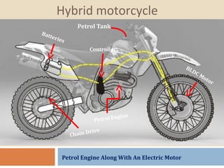
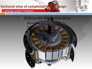
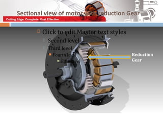
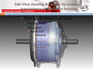
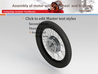


This project outlines the design, construction, and testing of a hybrid motorcycle. The concept combines an internal combustion engine with an electric hub motor and battery system. The electric motor provides propulsion up to 50 km/hr, after which the petrol engine engages. When running on petrol, the battery recharges. The goal is to achieve a range of 150km for Rs. 100 worth of fuel. Components like the brushless DC hub motor and lithium-ion batteries were selected, modeled, assembled and tested. Future work will optimize the controller programming and load testing to refine the hybrid system performance.