1. Homework II
Due on 28 Sep 2012
1. Dynamic response analysis by using MATLAB
25
1.1 Given the transfer function G ( s ) = 2
, evaluate the percent overshoot, settling time, peak
s + 4 s + 25
time and rise time by calculation. Verify your calculation by MATLAB simulation. (10 point)
1.2 Calculate the steady state error of the closed-loop system below by using the final value theorem if the
input r(t) is a unit step input. Verify your calculation by MATLAB simulation. (10 points)
1.3 A pole is added to the system of 1.1 at -200 and then moved to -20, -10, and -2. Simulate the step
response for each case and comment on the impact of the location of additional pole on the transient
response in 1.1. List the values of pole location in the order of the greatest to the least effect upon the pure
second-order transient response. (20 point)
1.4 A zero is added to the system of 1.1 at -200 and then moved to -50, -20, -10, -5, and -2.
Simulate the step response for each case and comment on the impact of the location of additional zero on
the transient response in 1.1. List the values of zero location in the order of the greatest to the least effect
upon the pure second-order transient response. (20 point)
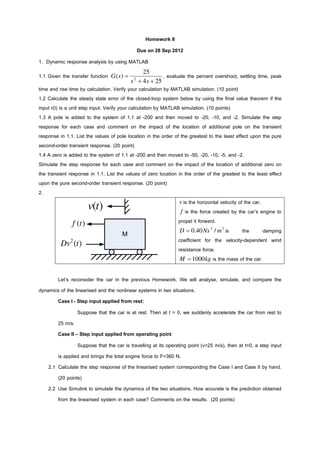
2.
v is the horizontal velocity of the car.
v(t) f is the force created by the car’s engine to
f (t ) propel it forward.
D = 0.40 Ns 2 / m 2 is the damping
M
coefficient for the velocity-dependent wind
Dv2 (t )
resistance force.
M = 1000 kg is the mass of the car.
Let’s reconsider the car in the previous Homework. We will analyse, simulate, and compare the
dynamics of the linearised and the nonlinear systems in two situations.
Case I - Step input applied from rest:
Suppose that the car is at rest. Then at t = 0, we suddenly accelerate the car from rest to
25 m/s.
Case II – Step input applied from operating point
Suppose that the car is travelling at its operating point (v=25 m/s), then at t=0, a step input
is applied and brings the total engine force to F=360 N.
2.1 Calculate the step response of the linearised system corresponding the Case I and Case II by hand.
(20 points)
2.2 Use Simulink to simulate the dynamics of the two situations. How accurate is the prediction obtained
from the linearised system in each case? Comments on the results. (20 points)