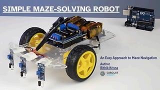
What is aMaze-Solving
Robot?
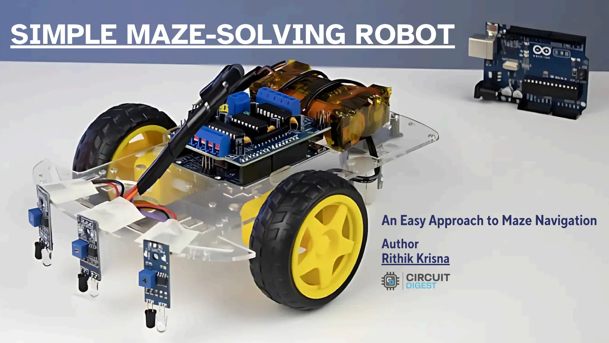
Maze-solving robots use
algorithms to autonomously
navigate through mazes.
Early competitions like
Micromouse (1970s) set the
foundation for this field.
This project uses a simple three-
sensor approach with the Left-
Hand Rule algorithm.
3.
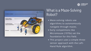
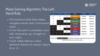
Maze-Solving Algorithm: TheLeft-
Hand Rule
The Hand-on-Wall Rule helps
navigate mazes with continuous
walls.
If the left path is available, turn
left; otherwise, go straight or
turn right.
Truth Table defines robot
behavior based on sensor inputs
(0 or 1).
4.
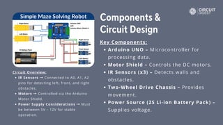
Components &
Circuit Design
KeyComponents:
Arduino UNO – Microcontroller for
processing data.
Motor Shield – Controls the DC motors.
IR Sensors (x3) – Detects walls and
obstacles.
Two-Wheel Drive Chassis – Provides
movement.
Power Source (2S Li-ion Battery Pack) –
Supplies voltage.
Circuit Overview:
IR Sensors → Connected to A0, A1, A2
pins for detecting left, front, and right
obstacles.
Motors → Controlled via the Arduino
Motor Shield.
Power Supply Considerations → Must
be between 5V – 12V for stable
operation.
5.
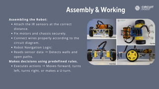
Assembly & Working
Assemblingthe Robot:
Attach the IR sensors at the correct
distance.
Fix motors and chassis securely.
Connect wires properly according to the
circuit diagram.
Robot Navigation Logic:
Reads sensor data → Detects walls and
open paths.
Makes decisions using predefined rules.
Executes actions → Moves forward, turns
left, turns right, or makes a U-turn.
6.
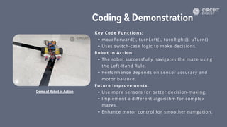
Coding & Demonstration
KeyCode Functions:
moveForward(), turnLeft(), turnRight(), uTurn()
Uses switch-case logic to make decisions.
Robot in Action:
The robot successfully navigates the maze using
the Left-Hand Rule.
Performance depends on sensor accuracy and
motor balance.
Future Improvements:
Use more sensors for better decision-making.
Implement a different algorithm for complex
mazes.
Enhance motor control for smoother navigation.
Demo of Robot in Action
7.
Link to GitHubRepository
https://github.com/Circuit-Digest/Simple-Maze-
Solving-Robot-using-Arduino-UNO
For a more in-depth tutorial, check out this
article:
https://circuitdigest.com/microcontroller-
projects/arduino-maze-solving-robot
www.circuitdigest.com
Robotics Projects|Arduino Projects|Raspberry Pi Projects| ESP32
Projects | AI Projects | IoT Projects