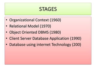
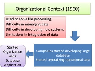
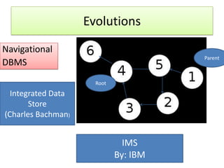
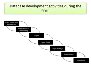
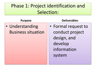
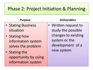
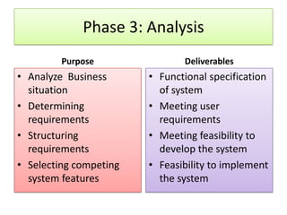
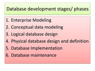
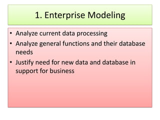
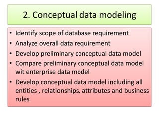
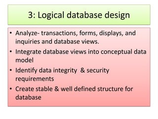
MODULE 1
DATABASE MANAGEMENT SYSTEMS
HISTORY OF DATABASE
    PROCESSING
STAGES
•   Organizational Context (1960)
•   Relational Model (1970)
•   Object Oriented DBMS (1980)
•   Client Server Database Application (1990)
•   Database using internet Technology (200)
Organizational Context (1960)
 Used to solve file processing
 Difficulty in managing data
 Difficulty in developing new systems
 Limitations in Integration of data


  Started
Organization       Companies started developing large
   wide                          database
 Database          Started centralizing operational data
Application
Limitations
•   Limited Technology
•   New Technology
•   Slow Applications
•   Unreliable Applications
•   Difficulty in Handling large Volume of Data
•   Slow Transactions
•   Unreliability of Database
What made the situation to improve ?
• More Education on Hardware and Software
• More experts evolved
• New methods of: controlling data
                 : protecting data
                 : backing of database
Evolutions
Navigational
                                       Parent
DBMS
                      Root
  Integrated Data
       Store
(Charles Bachman)


                               IMS
                             By: IBM
Relational Model (1970)
• Used application of mathematics: Relational
  Algebra
• Used to reduce the problem of storing large
  amount of data
• Developed by E.F.Codd
Benefits
•   Minimizes duplication
•   Eliminates processing & storing Errors
•   Data stored as tables: rows & columns
•   Concept of normalization used
•   Columns of 1 row relates the entities
Order    Customer     Customer    Item
Number   First Name   Last Name
A1010    John         Markose     Chair

A1011    Martin       Baby        Tables

A1012    Thomas       Stephen     Cupboard

A1013    Peter        Edwin       Computer
Resistance to Relational Model
•   Requires more computer resources
•   Makes the system slow
•   Impractical with less speed processing capacity
•   Examples:       INGRES,
                    PRTV,
                    Business System 12
                    Alphora Dataphor,
                    Rel
Object oriented DBMS

An object-oriented database management
system (OODBMS), sometimes shortened to
ODBMS for object database management
system), is a database management system
(DBMS) that supports the modelling and
creation of data as objects.
What is an object ?
• objects are key to understanding object-
  oriented technology
• Examples:
• dogs have
• state (name, color, breed, hungry)
and
• dogs have behavior (barking, fetching, and
  slobbering )
Examples:
• Bicycles have
• state (current gear, current pedal cadence,
  two wheels, number of gears)
and
• behavior (braking, accelerating, slowing down,
  changing gears).
Object
• Definition: An object is a software bundle of
  variables and related methods.
Drawbacks
• Difficult to use
• Very expensive to develop
• Already data in relational model needs
  conversion
• More suitable for engineering application
Client Server Database Application
                (1990)
• A client/server application is a piece of
  software that runs on a client computer and
  makes requests to a remote server.
• “Client/server systems operate in a networked
  environment, splitting the processing of an
  application between a front-end client and a
  back-end processor.”
Basic Elements
• A CSDB system consists of three primary
  software components:
• the client application (also called the front
  end),
• the data access layer (also called middleware),
  and
• the database server (also called a database
  engine, DBMS, data source, or back end).
Client Application
• The client application is responsible
  for accepting input from the user,
  submitting a query to the database
  server based on that input, receiving
  results from the server, formatting
  them, and presenting them to the
  user.
Data Access Layer
The data access layer is relatively
transparent to the user, but may be
very apparent to the developer of
the client app. It provides for the
application and API used to submit
queries to a data source .
Database Server
The database server accepts queries
from clients, processes them
concurrently, and returns results.
There are a number of different
query languages around, by far the
most prevalent of which is SQL
Problems


     Technical Support


                         Security

Connectivity
Database Models

• Hierarchical DBMS Model
• Network DBMS Model
• Relational DBMS Model
• Object Oriented DBMS Model
• Multi dimensional DBMS Model
• The hierarchical data model organizes data in a
  tree structure.
• There is a hierarchy of parent and child data
  segments.
• This structure implies that a record can have
  repeating information, generally in the child data
  segments.
• Data in a series of records, which have a set of
  field values attached to it.
• It collects all the instances of a specific record
  together as a record type.
• These record types are the equivalent of tables in
  the relational model, and with the individual
  records being the equivalent of rows.
A hierarchical database consists of the following:
• It contains nodes connected by branches.
• The top node is called the root.
• If multiple nodes appear at the top level, the
  nodes are called root segments.
• The parent of node is a node directly above a
  node
• Each node (with the exception of the root) has
  exactly one parent.
• The child of node is the node directly below the
  node and connected by a branch.
• One parent may have many children.
Network Model
• The network database organizes data in a
  network structure.
• Any column in the network structure can be
  linked to any other like a tree structure.
• A network structure can be described in
  terms of parents and children.
• This model allows having more than one
  parent.
Network Model
• Network DBMS have found not much more
  acceptance than the hierarchical DBMS.
• They have the same flexibility limitations as
  hierarchical database:

• the more powerful structure for representing
  data relationships allows a more realistic
  modeling of geographic phenomena.
• However network database tend to become
  overlay complex too easily.
Relational Model

• The relational database organizes data in
  tables.
• Each table is identified by a unique table
  name, and is organized by rows and columns.
• Each column within a table also has a unique
  name. Columns store the values for a specific
  attribute
• Rows represent one record in the table.
Properties of Relational Tables:
•   Values Are Atomic
•   Each Row is Unique
•   Column Values Are of the Same Kind
•   The Sequence of Columns is Insignificant
•   The Sequence of Rows is Insignificant
•   Each Column Has a Unique Name
One-to-one Relationship-

• One-to-one Relationship-
  Here one and only one record in the
  destination table is related to one and only
  one record in the source table.
One to one relationship
One-to-Many Relationship-


• This means that one record in the destination
  table may be related to more than one record
  in the source
One-to-Many Relationship-
Many-to-One Relationship


• This type of relationship is just opposite to the
  One-to-Many Relationship. Here two or more
  records in the destination table may be
  related to one record in the source table.
Many-to-One Relationship
Object Oriented Model
• The object oriented data model manages data
  through object.
• An object is a collection of data elements and
  operations that together are considered as
  single entity.
Multi Dimensional Database Model
• A multidimensional database (MDB) is a type
  of database that is optimized for data
  warehouse and online analytical processing
  (OLAP) applications.
• Multidimensional databases are frequently
  created using input from existing relational
  databases. Whereas a relational database is
  typically accessed using a Structured Query
  Language (SQL)
DATABSE COMPONENTS
•   Data Repository        •   System Software
•   DBMS                   •   Network Application
•   Hardware               •   Front Tools
•   Procedure Interface    •   Users
•   Application Software
•   Practitioners
•   Data Dictionary
APPLICATION INTERFACE

USERS
                                                          PRACTIONERS
                   PROCEDURE INTERFACE


                                       QUERY
               APPLICATION           REPORTING
                SOFTWARE             FRONT END
                                       TOOLS

DATABASE
            DATA                                  DATA
COMPON-    REPOS              DBMS               DICTIO
                                                 NARY
  ENTS     ITORY


                             HARDWARE
Data Repository
• Data Repository is a logical (and sometimes
  physical) partitioning of data where multiple
  databases which apply to specific applications
  or sets of applications reside.
Procedure interface
• The characteristics of a procedure that is
  executed on the database

• Example
SQL:>/ CREATE TABLE <Table name>
Data Dictionary
• A data dictionary is a collection of descriptions
  of the data objects or items in a data model
  for the benefit of programmers and others
  who need to refer to them.
Data dictionary : sample
Database Development Process
Enterprise data modelling
• Is the first step in database development, in
  which the scope and general contents of
  organisational databases are specified
• Graphical representation of data used by an
  enterprise or company
• Gives a helicopter view of the data and data
  transactions of the organisation
•
Enterprise data modelling
• Data model encompass both current and historical data of
  the organisation
• The model should reflect both the data and the processes
  of the organisation, plus the views of these components
  required by the various sections of the organisation.
• Example:
• sales data (invoices etc.) will be viewed from a monetary
  aspect by the accountant, from a quantitative aspect by the
  store staff and from both these aspects by the marketing
  people
Information System Architecture (ISA)
6 Key Components:
1. Data
2. Process
3. Network
4. People
5. Events and points in Time
6. Reason
1. Data
The processed information
The information that need to be exchanged,
  recorded, processed and verified, and
  classified and stored.
2. Process
• The event that manipulates the data
Example:
Pos (Point of Sales): Billing of items
Bank : withdrawal or deposit of money by a
  customer
3. Network
• Network transports the data around
  the organization and between the
  organizations and the key business
  partners.
4. People
• The entities who perform the process
• They are the source of information and
  receiver of information
Example:
Pos: Sender of information: Billing clerk
      Receiver of Information: Store manager
5. Events and points in time
6. Reasons
• Reasons for events
• Rules that govern the process
• Example: Customer cash withdrawal at ATM
ATM transaction
Sl. No   Event         Process       Action
1        Enter Pin     Verify Pin    Authorize
2        Enter         Choose        Authenticate
         Transaction   Transaction
         Type
3        Enter         Verify        Allow
         Amount        balance       Withdrawal
enterprise data model (Pine Valley Furniture Company)
Information Engineering
• “A data-oriented methodology to create and maintain
  information systems.”
• Top-down planning approach.
• Four steps:
   – Planning (Results in an Information Systems Architecture)
   – Analysis – meet the various members of the organisation
      (from top to bottom) to discuss and agree on the data
      requirements and the processes involved
   – Design
   – Implementation
Information Engineering Planning
                  phase
1.   Identify Strategic Planning Factors
a.   Goals
b.   Critical Success factors
c.   Problem Areas
Information Engineering Planning
                phase
2. Identify Corporate Planning Objects
a. Organizational Units
b. Location
c. Business Functions
d. Entity Types
Information Engineering Planning
                phase
3. Develop Enterprise Model
a. Functional decomposition
b. Entity- Relationship diagram
c. Planning Matrices
Example of process decomposition of an order fulfillment function
Planning matrices
• Provide an explicit approach for describing
  business requirements
• Location to function (which business function
  is being performed at which location)
• Unit to function (which business functions are
  the responsibility of which business units)
• IS application to data entity (explains how
  each information system interacts with each
  data entity)
Planning matrices
• Supporting function to data entity (which data
  are captured, used, updated, deleted within
  each function)
• IS application to business objective (shows
  which information systems support each
  business objective)
Systems development life cycle (SDLC)
• Is a complete set of steps that a team of IS professionals
  follow to specify, develop, maintain and replace information
  systems
• Process is often viewed as a cascade of steps (see following
  figure)
• Cascade or ‘waterfall’ approach as each step flows into the
  next – though steps can overlap in time and it is possible to
  backtrack when prior decisions need to be reconsidered
Database development activities during the
                         SDLC

Project Identification
   and Selection

                         Project Initiation
                          and Planning

                                              Analysis


                                                         Logical Design


                                                                          Physical Design


                                                                                            Implementation


                                                                                                             Maintenance
Phase 1: Project identification and
              Selection:
       Purpose               Deliverables
• Understanding        • Formal request to
  Business situation     conduct project
                         design, and
                         develop
                         information
                         system
Phase 2: Project Initiation & Planning

        Purpose                Deliverables
• Stating Business       • Written request to
  situation                study the possible
• Stating how              changes to existing
  information system       system or the
  solves the problem       development of a
• Stating the              new system
  opportunity by using
  information system
Phase 3: Analysis
         Purpose               Deliverables
• Analyze Business      • Functional specification
  situation               of system
• Determining           • Meeting user
  requirements            requirements
• Structuring           • Meeting feasibility to
  requirements            develop the system
• Selecting competing   • Feasibility to implement
  system features         the system
Phase 4: Logical Design
        Purpose            Deliverables
• To elicit and     Detailed functional
  structure all       specification of :
  information       a. Data
  requirements      b. Forma
                    c. Reports
                    d. Displays
                    e. Processing Rules
Phase 5: Physical design
       Purpose             Deliverables
• To develop       •   Computer Program
  technology and   •   Database structures
  Organizational   •   Technology purchase
  specifications
                   •   Physical site plans
                   •   Organizational
                       redesigns
Phase 6: Implementation:
        Purpose              Deliverables
• To write programs    • Programs that work
• Build data files       accurately to
• Test & install new     specification
  system               • Documentation
• Train users          • Training materials
• finalize
  documentation
Phase 7: Maintenance
       Purpose               Deliverables
• Monitor operations   • Periodic audits to
  and usefulness of      check the accuracy
  system                 of the system
• Repair and enhance
  the system
Database development stages/ phases

1.   Enterprise Modeling
2.   Conceptual data modeling
3.   Logical database design
4.   Physical database design and definition
5.   Database Implementation
6.   Database maintenance
1. Enterprise Modeling
• Analyze current data processing
• Analyze general functions and their database
  needs
• Justify need for new data and database in
  support for business
2. Conceptual data modeling
• Identify scope of database requirement
• Analyze overall data requirement
• Develop preliminary conceptual data model
• Compare preliminary conceptual data model
  wit enterprise data model
• Develop conceptual data model including all
  entities , relationships, attributes and business
  rules
3: Logical database design
• Analyze- transactions, forms, displays, and
  inquiries and database views.
• Integrate database views into conceptual data
  model
• Identify data integrity & security
  requirements
• Create stable & well defined structure for
  database
4. Physical database design &
               definition

• Define database to DBMS
• Decide on physical organization of data
• Design database processing programs
5. Database Implementation


• Code & test database processing programs
• Complete database documentation & training
  materials
• Install database and convert data from prior
  systems
6. Database Maintenance
• Analyze database and database applications to
  ensure that evolving information
  requirements are met
• Tune database for improved performance
• Fix errors in database and database
  applications and recover database when it is
  contaminated.
Lets wind up…………..
•   Data, Database, Database Management System
•   Relationship of application programs with DBMS
•   Definition of database
•   Short history of database processing
•   Types of database
•   Components of database system
•   Creating the database
•   Developing databases

History of database processing module 1 (2)

  • 1.
  • 2.
  • 3.
    STAGES • Organizational Context (1960) • Relational Model (1970) • Object Oriented DBMS (1980) • Client Server Database Application (1990) • Database using internet Technology (200)
  • 4.
    Organizational Context (1960) Used to solve file processing Difficulty in managing data Difficulty in developing new systems Limitations in Integration of data Started Organization Companies started developing large wide database Database Started centralizing operational data Application
  • 5.
    Limitations • Limited Technology • New Technology • Slow Applications • Unreliable Applications • Difficulty in Handling large Volume of Data • Slow Transactions • Unreliability of Database
  • 6.
    What made thesituation to improve ? • More Education on Hardware and Software • More experts evolved • New methods of: controlling data : protecting data : backing of database
  • 7.
    Evolutions Navigational Parent DBMS Root Integrated Data Store (Charles Bachman) IMS By: IBM
  • 8.
    Relational Model (1970) •Used application of mathematics: Relational Algebra • Used to reduce the problem of storing large amount of data • Developed by E.F.Codd
  • 10.
    Benefits • Minimizes duplication • Eliminates processing & storing Errors • Data stored as tables: rows & columns • Concept of normalization used • Columns of 1 row relates the entities
  • 11.
    Order Customer Customer Item Number First Name Last Name A1010 John Markose Chair A1011 Martin Baby Tables A1012 Thomas Stephen Cupboard A1013 Peter Edwin Computer
  • 12.
    Resistance to RelationalModel • Requires more computer resources • Makes the system slow • Impractical with less speed processing capacity • Examples: INGRES, PRTV, Business System 12 Alphora Dataphor, Rel
  • 13.
    Object oriented DBMS Anobject-oriented database management system (OODBMS), sometimes shortened to ODBMS for object database management system), is a database management system (DBMS) that supports the modelling and creation of data as objects.
  • 14.
    What is anobject ? • objects are key to understanding object- oriented technology • Examples: • dogs have • state (name, color, breed, hungry) and • dogs have behavior (barking, fetching, and slobbering )
  • 15.
    Examples: • Bicycles have •state (current gear, current pedal cadence, two wheels, number of gears) and • behavior (braking, accelerating, slowing down, changing gears).
  • 16.
    Object • Definition: Anobject is a software bundle of variables and related methods.
  • 17.
    Drawbacks • Difficult touse • Very expensive to develop • Already data in relational model needs conversion • More suitable for engineering application
  • 18.
    Client Server DatabaseApplication (1990) • A client/server application is a piece of software that runs on a client computer and makes requests to a remote server. • “Client/server systems operate in a networked environment, splitting the processing of an application between a front-end client and a back-end processor.”
  • 19.
    Basic Elements • ACSDB system consists of three primary software components: • the client application (also called the front end), • the data access layer (also called middleware), and • the database server (also called a database engine, DBMS, data source, or back end).
  • 21.
    Client Application • Theclient application is responsible for accepting input from the user, submitting a query to the database server based on that input, receiving results from the server, formatting them, and presenting them to the user.
  • 22.
    Data Access Layer Thedata access layer is relatively transparent to the user, but may be very apparent to the developer of the client app. It provides for the application and API used to submit queries to a data source .
  • 23.
    Database Server The databaseserver accepts queries from clients, processes them concurrently, and returns results. There are a number of different query languages around, by far the most prevalent of which is SQL
  • 24.
    Problems Technical Support Security Connectivity
  • 25.
    Database Models • HierarchicalDBMS Model • Network DBMS Model • Relational DBMS Model • Object Oriented DBMS Model • Multi dimensional DBMS Model
  • 26.
    • The hierarchicaldata model organizes data in a tree structure. • There is a hierarchy of parent and child data segments. • This structure implies that a record can have repeating information, generally in the child data segments. • Data in a series of records, which have a set of field values attached to it. • It collects all the instances of a specific record together as a record type. • These record types are the equivalent of tables in the relational model, and with the individual records being the equivalent of rows.
  • 28.
    A hierarchical databaseconsists of the following: • It contains nodes connected by branches. • The top node is called the root. • If multiple nodes appear at the top level, the nodes are called root segments. • The parent of node is a node directly above a node • Each node (with the exception of the root) has exactly one parent. • The child of node is the node directly below the node and connected by a branch. • One parent may have many children.
  • 29.
    Network Model • Thenetwork database organizes data in a network structure. • Any column in the network structure can be linked to any other like a tree structure. • A network structure can be described in terms of parents and children. • This model allows having more than one parent.
  • 31.
    Network Model • NetworkDBMS have found not much more acceptance than the hierarchical DBMS. • They have the same flexibility limitations as hierarchical database: • the more powerful structure for representing data relationships allows a more realistic modeling of geographic phenomena. • However network database tend to become overlay complex too easily.
  • 32.
    Relational Model • Therelational database organizes data in tables. • Each table is identified by a unique table name, and is organized by rows and columns. • Each column within a table also has a unique name. Columns store the values for a specific attribute • Rows represent one record in the table.
  • 34.
    Properties of RelationalTables: • Values Are Atomic • Each Row is Unique • Column Values Are of the Same Kind • The Sequence of Columns is Insignificant • The Sequence of Rows is Insignificant • Each Column Has a Unique Name
  • 35.
    One-to-one Relationship- • One-to-oneRelationship- Here one and only one record in the destination table is related to one and only one record in the source table.
  • 36.
    One to onerelationship
  • 37.
    One-to-Many Relationship- • Thismeans that one record in the destination table may be related to more than one record in the source
  • 38.
  • 39.
    Many-to-One Relationship • Thistype of relationship is just opposite to the One-to-Many Relationship. Here two or more records in the destination table may be related to one record in the source table.
  • 40.
  • 41.
    Object Oriented Model •The object oriented data model manages data through object. • An object is a collection of data elements and operations that together are considered as single entity.
  • 42.
    Multi Dimensional DatabaseModel • A multidimensional database (MDB) is a type of database that is optimized for data warehouse and online analytical processing (OLAP) applications. • Multidimensional databases are frequently created using input from existing relational databases. Whereas a relational database is typically accessed using a Structured Query Language (SQL)
  • 44.
    DATABSE COMPONENTS • Data Repository • System Software • DBMS • Network Application • Hardware • Front Tools • Procedure Interface • Users • Application Software • Practitioners • Data Dictionary
  • 45.
    APPLICATION INTERFACE USERS PRACTIONERS PROCEDURE INTERFACE QUERY APPLICATION REPORTING SOFTWARE FRONT END TOOLS DATABASE DATA DATA COMPON- REPOS DBMS DICTIO NARY ENTS ITORY HARDWARE
  • 46.
    Data Repository • DataRepository is a logical (and sometimes physical) partitioning of data where multiple databases which apply to specific applications or sets of applications reside.
  • 47.
    Procedure interface • Thecharacteristics of a procedure that is executed on the database • Example SQL:>/ CREATE TABLE <Table name>
  • 48.
    Data Dictionary • Adata dictionary is a collection of descriptions of the data objects or items in a data model for the benefit of programmers and others who need to refer to them.
  • 49.
  • 50.
  • 51.
    Enterprise data modelling •Is the first step in database development, in which the scope and general contents of organisational databases are specified • Graphical representation of data used by an enterprise or company • Gives a helicopter view of the data and data transactions of the organisation •
  • 52.
    Enterprise data modelling •Data model encompass both current and historical data of the organisation • The model should reflect both the data and the processes of the organisation, plus the views of these components required by the various sections of the organisation. • Example: • sales data (invoices etc.) will be viewed from a monetary aspect by the accountant, from a quantitative aspect by the store staff and from both these aspects by the marketing people
  • 53.
    Information System Architecture(ISA) 6 Key Components: 1. Data 2. Process 3. Network 4. People 5. Events and points in Time 6. Reason
  • 54.
    1. Data The processedinformation The information that need to be exchanged, recorded, processed and verified, and classified and stored.
  • 55.
    2. Process • Theevent that manipulates the data Example: Pos (Point of Sales): Billing of items Bank : withdrawal or deposit of money by a customer
  • 56.
    3. Network • Networktransports the data around the organization and between the organizations and the key business partners.
  • 57.
    4. People • Theentities who perform the process • They are the source of information and receiver of information Example: Pos: Sender of information: Billing clerk Receiver of Information: Store manager
  • 58.
    5. Events andpoints in time
  • 59.
    6. Reasons • Reasonsfor events • Rules that govern the process • Example: Customer cash withdrawal at ATM
  • 60.
    ATM transaction Sl. No Event Process Action 1 Enter Pin Verify Pin Authorize 2 Enter Choose Authenticate Transaction Transaction Type 3 Enter Verify Allow Amount balance Withdrawal
  • 61.
    enterprise data model(Pine Valley Furniture Company)
  • 62.
    Information Engineering • “Adata-oriented methodology to create and maintain information systems.” • Top-down planning approach. • Four steps: – Planning (Results in an Information Systems Architecture) – Analysis – meet the various members of the organisation (from top to bottom) to discuss and agree on the data requirements and the processes involved – Design – Implementation
  • 63.
    Information Engineering Planning phase 1. Identify Strategic Planning Factors a. Goals b. Critical Success factors c. Problem Areas
  • 64.
    Information Engineering Planning phase 2. Identify Corporate Planning Objects a. Organizational Units b. Location c. Business Functions d. Entity Types
  • 65.
    Information Engineering Planning phase 3. Develop Enterprise Model a. Functional decomposition b. Entity- Relationship diagram c. Planning Matrices
  • 67.
    Example of processdecomposition of an order fulfillment function
  • 68.
    Planning matrices • Providean explicit approach for describing business requirements • Location to function (which business function is being performed at which location) • Unit to function (which business functions are the responsibility of which business units) • IS application to data entity (explains how each information system interacts with each data entity)
  • 69.
    Planning matrices • Supportingfunction to data entity (which data are captured, used, updated, deleted within each function) • IS application to business objective (shows which information systems support each business objective)
  • 70.
    Systems development lifecycle (SDLC) • Is a complete set of steps that a team of IS professionals follow to specify, develop, maintain and replace information systems • Process is often viewed as a cascade of steps (see following figure) • Cascade or ‘waterfall’ approach as each step flows into the next – though steps can overlap in time and it is possible to backtrack when prior decisions need to be reconsidered
  • 71.
    Database development activitiesduring the SDLC Project Identification and Selection Project Initiation and Planning Analysis Logical Design Physical Design Implementation Maintenance
  • 72.
    Phase 1: Projectidentification and Selection: Purpose Deliverables • Understanding • Formal request to Business situation conduct project design, and develop information system
  • 73.
    Phase 2: ProjectInitiation & Planning Purpose Deliverables • Stating Business • Written request to situation study the possible • Stating how changes to existing information system system or the solves the problem development of a • Stating the new system opportunity by using information system
  • 74.
    Phase 3: Analysis Purpose Deliverables • Analyze Business • Functional specification situation of system • Determining • Meeting user requirements requirements • Structuring • Meeting feasibility to requirements develop the system • Selecting competing • Feasibility to implement system features the system
  • 75.
    Phase 4: LogicalDesign Purpose Deliverables • To elicit and Detailed functional structure all specification of : information a. Data requirements b. Forma c. Reports d. Displays e. Processing Rules
  • 76.
    Phase 5: Physicaldesign Purpose Deliverables • To develop • Computer Program technology and • Database structures Organizational • Technology purchase specifications • Physical site plans • Organizational redesigns
  • 77.
    Phase 6: Implementation: Purpose Deliverables • To write programs • Programs that work • Build data files accurately to • Test & install new specification system • Documentation • Train users • Training materials • finalize documentation
  • 78.
    Phase 7: Maintenance Purpose Deliverables • Monitor operations • Periodic audits to and usefulness of check the accuracy system of the system • Repair and enhance the system
  • 79.
    Database development stages/phases 1. Enterprise Modeling 2. Conceptual data modeling 3. Logical database design 4. Physical database design and definition 5. Database Implementation 6. Database maintenance
  • 80.
    1. Enterprise Modeling •Analyze current data processing • Analyze general functions and their database needs • Justify need for new data and database in support for business
  • 81.
    2. Conceptual datamodeling • Identify scope of database requirement • Analyze overall data requirement • Develop preliminary conceptual data model • Compare preliminary conceptual data model wit enterprise data model • Develop conceptual data model including all entities , relationships, attributes and business rules
  • 82.
    3: Logical databasedesign • Analyze- transactions, forms, displays, and inquiries and database views. • Integrate database views into conceptual data model • Identify data integrity & security requirements • Create stable & well defined structure for database
  • 83.
    4. Physical databasedesign & definition • Define database to DBMS • Decide on physical organization of data • Design database processing programs
  • 84.
    5. Database Implementation •Code & test database processing programs • Complete database documentation & training materials • Install database and convert data from prior systems
  • 85.
    6. Database Maintenance •Analyze database and database applications to ensure that evolving information requirements are met • Tune database for improved performance • Fix errors in database and database applications and recover database when it is contaminated.
  • 86.
    Lets wind up………….. • Data, Database, Database Management System • Relationship of application programs with DBMS • Definition of database • Short history of database processing • Types of database • Components of database system • Creating the database • Developing databases