Downloaded 85 times
![High Pressure Gas Quench
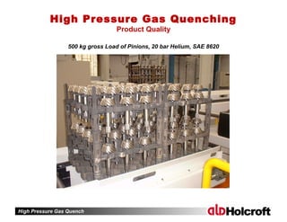
Bubble Boiling
Film Boiling
Convection
t = 10 s
750°C
700°C
700°C
600°C
500°C
400°C
300°C
200°C
Temperature distribution
t = 10 s
Heat transfer coefficient α
5000 10000 15000 20000
Öl
oil Wasser
water
[W/m K]
2
ref.: Stick, Tensi, HTM 50, 1995
Heat Transfer & Temperature Distribution
Immersion Quenching](https://image.slidesharecdn.com/highpressuregasquenching-150328134521-conversion-gate01/85/High-Pressure-Gas-Quenching-5-320.jpg)
![High Pressure Gas Quench
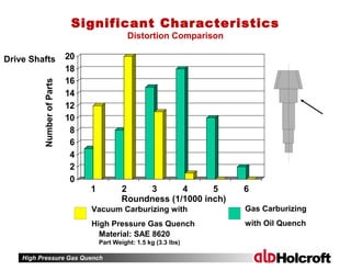
Heat transfer coefficient α
1000 2000 3000 4000 [W/m K]
2
Temperature distribution
750°C
650°C
550°C
450°C
350°C
250°C
Gas direction
Only convection
Heat Transfer & Temperature Distribution
High Pressure Gas Quenching](https://image.slidesharecdn.com/highpressuregasquenching-150328134521-conversion-gate01/85/High-Pressure-Gas-Quenching-6-320.jpg)
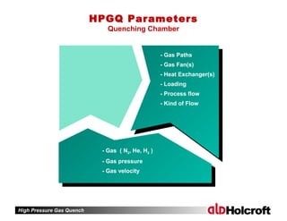
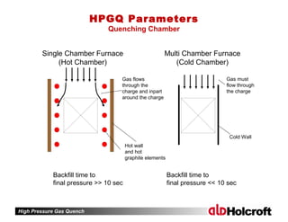
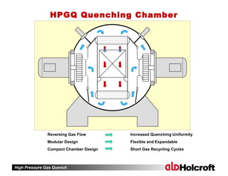
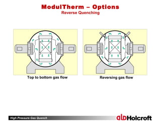

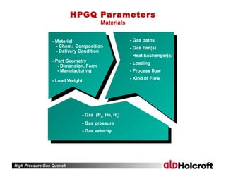
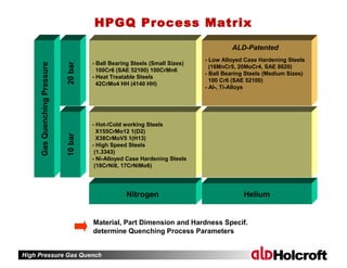
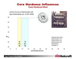
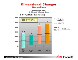
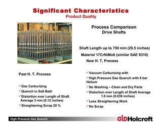

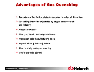
High pressure gas quenching (HPGQ) offers advantages like reduced hardening distortion and adjustable quenching intensity through gas pressure and velocity. This clean and non-toxic process integrates well into manufacturing lines, producing reproducible and high-quality results without the need for washing. Key parameters influencing HPGQ include gas type, pressure, velocity, and chamber design, which collectively impact the material's microstructure, hardness, and overall distortion.


![⚡[PDF BOOK]❤ Mukoita I, Cutting Techniques: Fish (The Japanese Culinary Acade...](https://cdn.slidesharecdn.com/ss_thumbnails/mukoita-i-cutting-techniques-fish-the-japanese-culinary-academys-complete-japanese-cuisine-210328071637-thumbnail.jpg?width=640&height=640&fit=bounds)


