High Speed Tempering of Gears-ASM PUNE - Feb - 2013
1. HIGH SPEED TEMPERING OF GEARS: A COMPARATIVE
STUDY
1 1 2
Ghorpade Pratap , Gowri S. , Grenier Mario
1 Highhtemp Furnaces, Bangluru (India), 2 Pyromaitre Inc, Canada
pratap.ghorpade@hightemp-furnaces.com
faster in presence of wind and a given sameHigh Speed Tempering: History of
temperature will feel much colder than the actualDevelopment
temperature,thisisknown aswind chillfactor.
QuestforQuality
Conversely a cold body will warm up much faster
The first high-speed unit was developed in 1990 in presence of hot wind. The effect of rapid air
for a high precise torsion spring maker. The movements wiping the body surface serves to
springs had two mobile legs moving as a result of break up the insulating layer of air boundary at the
stress relieving up to 20° angle position. Final surface of the object so that heat can be transferred
position had to be within +/- 3°. Traditionally mostdirectly.
stress relieve took 1 hour at 350°C. The Pyro that
Everything being equal, a Pyro will heat up a coldwas shipped yielded 30% rejected parts.The final
body between 2 and 3 times faster compared totemperature resulted at 460°C which was above
regular traditional ovens. Using a process ofrecommended and cycle time was down 3 to
stepped-elevated temperature increments in theminutes total from 60 minutes for CrSi6 mm wire!
different zones will maximize heat transferNo rejects; an in-line,ultra-lean process. Auditors
further,aswewillseelater.were puzzled. This process has since been
consistently proven over and over again by the
most stringent protocols and is now used not only
for stress-relieving of cold-forming of pre-
hardened parts, but with equal benefits for
temperingafterquenching.
In America, one out of every two cars on the road
contains at least one part from valve springs, axles,
CV Joints, suspension springs, car belt tensioners,
processed in one of several hundred Pyro units in
operation. ThermalEffect
TheScienceBehind PyroHeatTransfer Stress relieving and tempering is applying a given
amount of energy (Thermal Effect TE) toa partHeat can be transferred to a cold body by 3
depending of alloy type, process, part geometrydifferent means: Radiation Conduction
and desired results. This has been describedConvection.
scientifically by a number of scientific formulas.
Pyro uses convection as main means of (Larson Miller, Hollomount Jaffe) Each point
transferring heat to a metal part. Pyro uses the along the line represents equivalent thermal effect
reverse of wind chill effect factor familiar to those andis equivalenttotherecipe(s).
living in cold climates. A warm body will cool
Conventional oven processes use lower
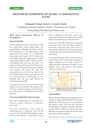
Fig. 1 Comparison between standard ovens
and Pyro heat transfer oven
100
th
ANNIVERSARY
1913-201301
Technical PapersTechnical PapersContentContent
2. temperatures for a longer time. Extremely fast on counter shaft 4thgear (20MnCr , case5
induction processes, common for tempering after carburised) andrear axle shaft (SAE 1541 &
induction hardening, use much higher 40Cr (B), Induction Hardened at High Temp4
temperatures for a much shorter time. The Pyro Chennai. Detailed results given below in Table 1
process worksin the middle between the two andTable2.
ranges.
ActualStandards and Practices
An oven is a heat transfer machine. However,
ovens are calibrated for temperature only and not
heat transfer. For instance 2 different ovens can
well pass heat uniformity surveys but they will
heatthesameloadverydifferently.
Therefore, standards were made so that even the
worst heat transferoven (which would be the
slowest) canproducegoodparts.
Automotive components are tempered to enhance
mechanical properties. Temperingcycle times are
approximately60to180minutes.
Trials
To demonstrate this process trials were conducted
Fig.2Larsen Miller Equivalent
Thermal Function
Fig. 3 Typical heat transfer
with a batch oven
Table 1
Counter shaft 4th gear
Material 20MnCr5 used for gears. All gears are
from same batch.
Tempering
Process
Custome
r Cycle
160º C -
90 min
Fast
temperin
g Cycle
200º C -
40 min
Customer
Specificati
on
Hardness
Traverse
Hardness
Drop
Distance
(mm)
Hardness
(Hv1)
Hardness
(Hv1)
--------
0.1 686 689
0.2 ·686 ·716
0.3 686 698
0.4 660 707
0.5 660 689
0.6 636 675
0.7 613 626
0.8 591 571
0.9 571 542
1 551 469
1.1 533 402
1.2 533 394
Case depth
(mm) 1 0.9
0.9-1.2
Surface
Hardness
HRC
59-60 58-59 60±2
Corehardne
ss HV1 ·400-413 ·319-318
· -
TBhardness
Hv1
436-443 329-331
-
Core
strength 130 99-103
87 Kg/
mm2 min
Tooth base
strength 142-145 106-109
105-145
kg/mm2
100
th
ANNIVERSARY
1913-201302
3. Conclusion
Fast tempering was compared to regular
tempering. To demonstrate this process, 4th speed
counter shaft gear (20MnCr5) case carburizedand
Rear axle shaft (SAE 1541 and 40Cr4(B)
InductionHardenedmaterialsweretested.
The cycle time reduction achieved was 40 min
against conventional 90 min for carburizing gears
and 30 min against 120 min for induction
hardening.
The reduction in tempering cycle time helps to
reduce cost, fuel consumption, throughput time,
andcarbonfootprint.
Table 2
Rear axle shaft
Materi
al
SAE 1541 and 40Cr4(B) shafts are used for
induction hardening and Pyro Tempering
Tempe
ring
Proces
s
Conventi
onal
Tempering
180ºC -
120 min
Pyro Tempered
195ºC -30min
Hardn
ess
Drop
·Distance
(mm)
·40Cr
(B)4
SAE 1541 ·40Cr
(B)4
·SAE
1541
0.1 584 592 610 614
0.3 604 615 617 630
0.5 ·612 ·621 ·625 632
1 610 621 632 621
2 619 608 641 625
3 619 594 638 600
4 584 571 540 565
5 261 378 277 257
6 260 248 277 269
·7 ·259 .244 . 261 . 270
8 254 257 266 257
Case
depth
(mm) 4 4
Surfac
e hard
ness
HRC 53
54-55
55-56
59-58
Core
hardne
ss
(HRC) 20
19-20
22
19-20
Fig. 4 Hardness drop for
case carburised Counter shaft 4th gear
Fig. 5 Hardness drop for rear
axle shaft (40Cr4(B) material)
Fig. 6 Hardness drop for rear axle
shaft (SAE 1541 material)
100
th
ANNIVERSARY
1913-201303
Technical PapersTechnical PapersContentContent