FACT:
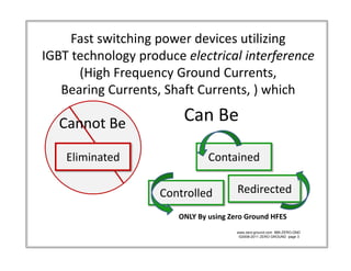
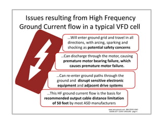
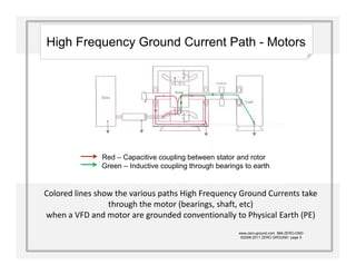
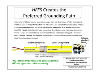
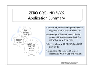
 Grounding is the most
misunderstood aspect of
 Electrical Distribution
Current Flow to Physical Earth 
                              in a Typical VFD Cell using 
                              i T i l VFD C ll i
                               conventional grounding
  •     POWER SUPPLY
  •     DRIVE  *typically utilizes IGBT technology
  •     MOTOR
  •     WIRING SYSTEM ( MOST NEGLECTED COMPONENT)
        WIRING SYSTEM ( MOST NEGLECTED COMPONENT)
                            Conventional input cabling                                   Conventional output cabling

                                                          Drive Frame ( V F D ) *
                  Transformer Case Frame                                                         Motor Frame


                                                                          OUTPUT
                                                                                                     Stator

                                                                  INPUT
                                                                                                    Windings

                                                           PE                       PE      PE
I f-g = high
    g                                   PE
frequency                                                                          PE                 PE
ground                        I f-g                       I f-g                                                I f-g
currents
                                                   Oscilloscope reads approximately
      PE NEC.Sect.250 PCC                           1,500 illi
                                                    1 500 milliamps going t ground
                                                                      i to       d

                                                                                           www.zero-ground.com 866-ZERO-GND
                                                                                            ©2008-2011 ZERO GROUND page 2
Fast switching power devices utilizing               
IGBT technology produce electrical interference
      (High Frequency Ground Currents,                   
   Bearing Currents, Shaft Currents, ) which
                                     )

   C      B
   Cannot Be               Can Be
                           Can Be

    Eliminated                    Contained

                       Controlled         Redirected
                                          R di t d

                          ONLY By using Zero Ground HFES
                                          www.zero-ground.com 866-ZERO-GND
                                           ©2008-2011 ZERO GROUND page 3
Issues resulting from High Frequency            
Ground Current flow in a typical VFD cell
                       …Will enter ground grid and travel in all 
                       …Will enter ground grid and travel in all
                       directions, with arcing, sparking and 
                       shocking as potential safety concerns

                   …Can discharge through the motor, causing   
                        d h        h    h h
                    premature motor bearing failure, which 
                       causes premature motor failure. 

                …Can re‐enter ground paths through the 
                ground and  disrupt sensitive electronic 
                equipment and adjacent drive systems
                equipment and adjacent drive systems
           …This HF ground current flow is the basis for 
         recommended output cable distance limitation 
             of 50 feet by most ASD manufacturers
               f 50 f   b       ASD        f
                                                www.zero-ground.com 866-ZERO-GND
                                                 ©2008-2011 ZERO GROUND page 4
High Frequency Ground Current Path - Motors


               Red Capacitive coupling b t
               R d–C       iti       li between stator and rotor
                                                   t t     d t
               Green – Inductive coupling through bearings to earth


Colored lines show the various paths High Frequency Ground Currents take 
                 through the motor (bearings, shaft, etc) 
when a VFD and motor are grounded conventionally to Physical Earth (PE)
                                                         www.zero-ground.com 866-ZERO-GND
                                                          ©2008-2011 ZERO GROUND page 5
HFES Creates the 
               Preferred Grounding Path
                  f    d       d      h
  Unlike other VFD Cable Systems (used only on output side), only Zero Ground HFES is designed and
  rated to be used on the input and output side of the Drive. Also unlike traditional VFD cabling, HFES is
  a completely passive system, and can be used wherever greater than 50 ft. lengths are required.
  Our HFES Flexible Cable Assembly takes conventional Drive System wiring materials and combines
  them in a unique and patented design to create a continuous preferred grounding path. That is how
  HFES Contains, Controls and Redirects High Frequency Ground Currents and other nuisance noise
  AWAY from physical earth (ground).                                                                     Industry
                                                                                                         standard
                      Inner Component                       Outer Component                              fitting


                                 NOTE: Inner Component is inserted into
                                 Outer Component when shipped
                                                                               Patents have been issued for
UL listed components and cable assembly
              p                        y                                          ZERO GROUND HFES
                                                                               Components and I t ll ti
                                                                               C         t    d Installation
MSHA approved cable assembly                                                            Method
                                                                                   www.zero-ground.com 866-ZERO-GND
                                                                                    ©2008-2011 ZERO GROUND page 6
ZERO GROUND HFES
                ZERO GROUND 
                ZERO GROUND HFES
                Application Summary

                            A system of passive wiring components 
            Low                engineered to a specific drive cell
                               engineered to a specific drive cell
          Voltage 
          (1000V)           Patented flexible cable assembly and 
                               patented installation method, for 
500 HP 
500 HP                         retrofit or new drive cells
                               retrofit or new drive cells
or less
               INPUT and    Fully compliant with NEC 250 and CSA 
                OUTPUT          Section 10
                      g
                 wiring 
                 system     Not designed to resolve all issues 
                               associated with drives and motors


                                           www.zero-ground.com 866-ZERO-GND
                                            ©2008-2011 ZERO GROUND page 7
HFES delivers continuous ROI –
        Why ZERO GROUND HFES is your best 
        Why ZERO GROUND HFES is your best
               long‐term solution
Measurable hi h f
M         bl high frequency ground currents are always present in a Drive 
                                   d       t       l            ti D i
     System, with the potential to create safety issues, induce premature 
     motor bearing failure and disrupt sensitive devices and systems on 
     the same or adjacent grounding grids.
     the same or adjacent grounding grids
‐‐‐Enables upfront planning for prevention instead of funding ongoing 
     maintenance and unplanned downtime recovery
‐‐‐No regular maintenance required 
   No regular maintenance required
‐‐‐No active components to complicate your system
‐‐‐No frequency dependent components (like filters)
‐‐‐No routinely replaceable components (like brushes)
‐‐‐No distance limitations with HFES (cable assembly runs can be moved 
     or extended as needed)

                                                     www.zero-ground.com 866-ZERO-GND
                                                     ©2008-2011 ZERO GROUND page 8

HFES Quick Intro

  • 1.
    FACT: Grounding isthe most misunderstood aspect of Electrical Distribution
  • 2.
    Current Flow to Physical Earth  in a Typical VFD Cell using  i T i l VFD C ll i conventional grounding • POWER SUPPLY • DRIVE  *typically utilizes IGBT technology • MOTOR • WIRING SYSTEM ( MOST NEGLECTED COMPONENT) WIRING SYSTEM ( MOST NEGLECTED COMPONENT) Conventional input cabling Conventional output cabling Drive Frame ( V F D ) * Transformer Case Frame Motor Frame OUTPUT Stator INPUT Windings PE PE PE I f-g = high g PE frequency PE PE ground I f-g I f-g I f-g currents Oscilloscope reads approximately PE NEC.Sect.250 PCC 1,500 illi 1 500 milliamps going t ground i to d www.zero-ground.com 866-ZERO-GND ©2008-2011 ZERO GROUND page 2
  • 3.
    Fast switching power devices utilizing                IGBT technology produce electrical interference (High Frequency Ground Currents,                    Bearing Currents, Shaft Currents, ) which ) C B Cannot Be Can Be Can Be Eliminated Contained Controlled Redirected R di t d ONLY By using Zero Ground HFES www.zero-ground.com 866-ZERO-GND ©2008-2011 ZERO GROUND page 3
  • 4.
    Issues resulting from High Frequency             Ground Current flow in a typical VFD cell …Will enter ground grid and travel in all  …Will enter ground grid and travel in all directions, with arcing, sparking and  shocking as potential safety concerns …Can discharge through the motor, causing    d h h h h premature motor bearing failure, which  causes premature motor failure.  …Can re‐enter ground paths through the  ground and  disrupt sensitive electronic  equipment and adjacent drive systems equipment and adjacent drive systems …This HF ground current flow is the basis for  recommended output cable distance limitation  of 50 feet by most ASD manufacturers f 50 f b ASD f www.zero-ground.com 866-ZERO-GND ©2008-2011 ZERO GROUND page 4
  • 5.
    High Frequency GroundCurrent Path - Motors Red Capacitive coupling b t R d–C iti li between stator and rotor t t d t Green – Inductive coupling through bearings to earth Colored lines show the various paths High Frequency Ground Currents take  through the motor (bearings, shaft, etc)  when a VFD and motor are grounded conventionally to Physical Earth (PE) www.zero-ground.com 866-ZERO-GND ©2008-2011 ZERO GROUND page 5
  • 6.
    HFES Creates the  Preferred Grounding Path f d d h Unlike other VFD Cable Systems (used only on output side), only Zero Ground HFES is designed and rated to be used on the input and output side of the Drive. Also unlike traditional VFD cabling, HFES is a completely passive system, and can be used wherever greater than 50 ft. lengths are required. Our HFES Flexible Cable Assembly takes conventional Drive System wiring materials and combines them in a unique and patented design to create a continuous preferred grounding path. That is how HFES Contains, Controls and Redirects High Frequency Ground Currents and other nuisance noise AWAY from physical earth (ground). Industry standard Inner Component Outer Component fitting NOTE: Inner Component is inserted into Outer Component when shipped Patents have been issued for UL listed components and cable assembly p y ZERO GROUND HFES Components and I t ll ti C t d Installation MSHA approved cable assembly Method www.zero-ground.com 866-ZERO-GND ©2008-2011 ZERO GROUND page 6
  • 7.
    ZERO GROUND HFES ZERO GROUND  ZERO GROUND HFES Application Summary A system of passive wiring components  Low  engineered to a specific drive cell engineered to a specific drive cell Voltage  (1000V) Patented flexible cable assembly and  patented installation method, for  500 HP  500 HP retrofit or new drive cells retrofit or new drive cells or less INPUT and  Fully compliant with NEC 250 and CSA  OUTPUT  Section 10 g wiring  system Not designed to resolve all issues  associated with drives and motors www.zero-ground.com 866-ZERO-GND ©2008-2011 ZERO GROUND page 7
  • 8.
    HFES delivers continuous ROI – Why ZERO GROUND HFES is your best  Why ZERO GROUND HFES is your best long‐term solution Measurable hi h f M bl high frequency ground currents are always present in a Drive  d t l ti D i System, with the potential to create safety issues, induce premature  motor bearing failure and disrupt sensitive devices and systems on  the same or adjacent grounding grids. the same or adjacent grounding grids ‐‐‐Enables upfront planning for prevention instead of funding ongoing  maintenance and unplanned downtime recovery ‐‐‐No regular maintenance required  No regular maintenance required ‐‐‐No active components to complicate your system ‐‐‐No frequency dependent components (like filters) ‐‐‐No routinely replaceable components (like brushes) ‐‐‐No distance limitations with HFES (cable assembly runs can be moved  or extended as needed) www.zero-ground.com 866-ZERO-GND ©2008-2011 ZERO GROUND page 8