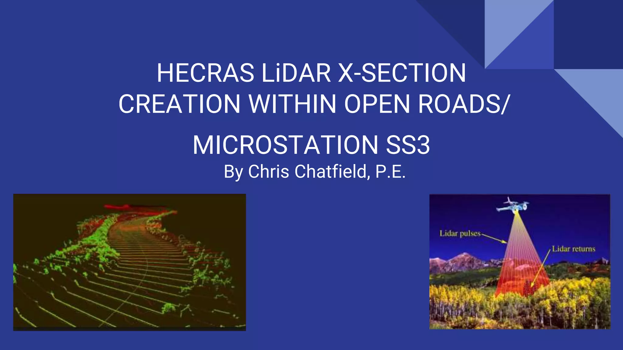
HECRAS LiDAR X-SECTION
CREATION WITHIN OPEN ROADS/
MICROSTATION SS3
By Chris Chatfield, P.E.
STEPS TO SUCCESSFUL CREATION
1. Locate Data Source
2. Judge Appropriate ‘Tightness’ of Data
3. Formation of GEOPAK TIN
4. Cross Section Generation
WHERE DO YOU
GET THE
DATA?????
Depending on your area….look
for data repositories or city
governments in your area
JUDGING APPROPRIATE ‘TIGHTNESS’ OF DATA
1. What is the resolution of the dataset?
2. What are the vegetation characteristics of the site?
a. Dense foliage will distort the collection
There are a few questions to ask with this in mind:
1. Is the tightness of the best available dataset appropriate for the risk
associated with the hydraulic structure in question?
2. Does ground survey analysis need to be done to supplement the
LiDAR?
GEOPAK TIN CREATION
FROM LiDAR
GEOPAK TIN CREATION FROM LiDAR (1/3)
1. Open the Point Cloud Tools from
Tools>Point Cloud on the main menu.
2. Select File>Attach. Specify the LAS file
downloaded. OpenRoads will first convert the
LAS to its native point cloud format (POD).
Specify the units and geographic projection
associated with the dataset.
OpenRoads Technology within Microstation SS3 does not allow the user to specify skewed cross sections
and therefore it’s recommended to use a hybrid method to complete. An abbreviated Step-by-step
methodology is outlined below.
GEOPAK TIN CREATION FROM LiDAR (2/3)
3. The point cloud should now be attached to
the design file. Repeat Steps 1-2 for each LAS
needed for the project. Due to the file size, it’s
beneficial to clip out extraneous information.
Highlight all needed point clouds, use Edit>Clip,
and the selection tools available to create the
needed point cloud selection. In order to create
an actual new dataset, right-click the data to
export it.
4. The point cloud also contains data besides
the needed ground points and these can be
filtered out during the export process. In the
export dialog, specify ‘Ground’ in the
‘Classification Filter.’ In addition, specify ‘Clip’ in
the ‘Regional Filter’ (not shown below). Select
‘OK’.
GEOPAK TIN CREATION FROM LiDAR (3/3)
5. Attach the POD file created previously and
inspect to ensure steps were performed
correctly. Open the ‘Create Terrain’ dialog within
the ‘Terrain Tools’ and specify ‘ From Point
Cloud’. Use the feature definition drop down and
specify ‘Existing Contours’.
6. Hover over the newly-created terrain model to
select ‘Export Terrain Model’. Use the ‘Export
Format’ drop down to specify ‘GeoPAK TIN’.
CROSS SECTION GENERATION
CROSS SECTION GENERATION (1/4)
1. Reference in statewide stream data,
floodplain mapping, and roadway mapping
to create an approximate flowline for
channel at the project location. Create a
*.PRJ and *.GPK file for project. Store the
stream line as an alignment with the use
of ‘Store Graphics’ in GEOPAK.
2. Open the ‘Draw Pattern Lines’ tool location in
the ‘Cross Section’ toolbox. Specify the job and
chain associated with the cross sections. Use
the floodplain mapping data (if available) to
determine the left and right cross section offset.
Set the increment to 50’ and a beginning station
as 300’ from the stricture as a starting point.
Modification may need to be performed later
based on analysis.
CROSS SECTION GENERATION (2/4)
3. Generate 1’ or 5’ contours (depending on the
dataset) from the LiDAR TIN with the use of
‘Load DTM Features’.
4. Add cross sections if needed. Use the
‘Modify’ tools to add/subtract vertices and
ensure that the pattern lines are perpendicular
to the contours. The patterns will likely be
‘skewed’ . In addition, make sure that they are
‘lines’ and not ‘line strings’ by ‘dropping’ the
element.
CROSS SECTION GENERATION (3/4)
5. Open the ‘Cut Cross Sections from Ground’
tool and specify the pattern line attributes as
well as the location of the TIN file.
6. These sections can either be directly
imported into HECRAS through the ‘HECRAS’
tool (located in ‘Cross Section Reports’) or
convert the cross section into data points
though the ‘Profile Grade’ tool (also located in
‘Cross Section Reports’). These data points can
be copied/pasted in HECRAS and allow a little
more control over the data.
CROSS SECTION GENERATION (4/4)
7. If the direct import option is utilized, it may be advised to turn off the ‘GIS Cut Lines’. If this option is off,
it will allow you to manipulate the cross sections (such as making the upstream cross section the same as
the downstream cross section) without changing how the plan view looks. The plan view is not technically
involved in the calculations, but could be disorienting.
SOURCES
http://vcgi.vermont.gov/LiDAR
http://support.civilgeo.com/knowledge-base/assigning-survey-data-to-hec-ras-cross-sections/
Tnris.org
http://www.fhwa.dot.gov/engineering/hydraulics/software/hecras_microstation.pdf

HEC-RAS LiDAR Cross Sections With Microstation SS3 V8i

  • 1.
    HECRAS LiDAR X-SECTION CREATIONWITHIN OPEN ROADS/ MICROSTATION SS3 By Chris Chatfield, P.E.
  • 2.
    STEPS TO SUCCESSFULCREATION 1. Locate Data Source 2. Judge Appropriate ‘Tightness’ of Data 3. Formation of GEOPAK TIN 4. Cross Section Generation
  • 3.
    WHERE DO YOU GETTHE DATA????? Depending on your area….look for data repositories or city governments in your area
  • 4.
    JUDGING APPROPRIATE ‘TIGHTNESS’OF DATA 1. What is the resolution of the dataset? 2. What are the vegetation characteristics of the site? a. Dense foliage will distort the collection There are a few questions to ask with this in mind: 1. Is the tightness of the best available dataset appropriate for the risk associated with the hydraulic structure in question? 2. Does ground survey analysis need to be done to supplement the LiDAR?
  • 5.
  • 6.
    GEOPAK TIN CREATIONFROM LiDAR (1/3) 1. Open the Point Cloud Tools from Tools>Point Cloud on the main menu. 2. Select File>Attach. Specify the LAS file downloaded. OpenRoads will first convert the LAS to its native point cloud format (POD). Specify the units and geographic projection associated with the dataset. OpenRoads Technology within Microstation SS3 does not allow the user to specify skewed cross sections and therefore it’s recommended to use a hybrid method to complete. An abbreviated Step-by-step methodology is outlined below.
  • 7.
    GEOPAK TIN CREATIONFROM LiDAR (2/3) 3. The point cloud should now be attached to the design file. Repeat Steps 1-2 for each LAS needed for the project. Due to the file size, it’s beneficial to clip out extraneous information. Highlight all needed point clouds, use Edit>Clip, and the selection tools available to create the needed point cloud selection. In order to create an actual new dataset, right-click the data to export it. 4. The point cloud also contains data besides the needed ground points and these can be filtered out during the export process. In the export dialog, specify ‘Ground’ in the ‘Classification Filter.’ In addition, specify ‘Clip’ in the ‘Regional Filter’ (not shown below). Select ‘OK’.
  • 8.
    GEOPAK TIN CREATIONFROM LiDAR (3/3) 5. Attach the POD file created previously and inspect to ensure steps were performed correctly. Open the ‘Create Terrain’ dialog within the ‘Terrain Tools’ and specify ‘ From Point Cloud’. Use the feature definition drop down and specify ‘Existing Contours’. 6. Hover over the newly-created terrain model to select ‘Export Terrain Model’. Use the ‘Export Format’ drop down to specify ‘GeoPAK TIN’.
  • 9.
  • 10.
    CROSS SECTION GENERATION(1/4) 1. Reference in statewide stream data, floodplain mapping, and roadway mapping to create an approximate flowline for channel at the project location. Create a *.PRJ and *.GPK file for project. Store the stream line as an alignment with the use of ‘Store Graphics’ in GEOPAK. 2. Open the ‘Draw Pattern Lines’ tool location in the ‘Cross Section’ toolbox. Specify the job and chain associated with the cross sections. Use the floodplain mapping data (if available) to determine the left and right cross section offset. Set the increment to 50’ and a beginning station as 300’ from the stricture as a starting point. Modification may need to be performed later based on analysis.
  • 11.
    CROSS SECTION GENERATION(2/4) 3. Generate 1’ or 5’ contours (depending on the dataset) from the LiDAR TIN with the use of ‘Load DTM Features’. 4. Add cross sections if needed. Use the ‘Modify’ tools to add/subtract vertices and ensure that the pattern lines are perpendicular to the contours. The patterns will likely be ‘skewed’ . In addition, make sure that they are ‘lines’ and not ‘line strings’ by ‘dropping’ the element.
  • 12.
    CROSS SECTION GENERATION(3/4) 5. Open the ‘Cut Cross Sections from Ground’ tool and specify the pattern line attributes as well as the location of the TIN file. 6. These sections can either be directly imported into HECRAS through the ‘HECRAS’ tool (located in ‘Cross Section Reports’) or convert the cross section into data points though the ‘Profile Grade’ tool (also located in ‘Cross Section Reports’). These data points can be copied/pasted in HECRAS and allow a little more control over the data.
  • 13.
    CROSS SECTION GENERATION(4/4) 7. If the direct import option is utilized, it may be advised to turn off the ‘GIS Cut Lines’. If this option is off, it will allow you to manipulate the cross sections (such as making the upstream cross section the same as the downstream cross section) without changing how the plan view looks. The plan view is not technically involved in the calculations, but could be disorienting.
  • 14.