Downloaded 22 times
![OK
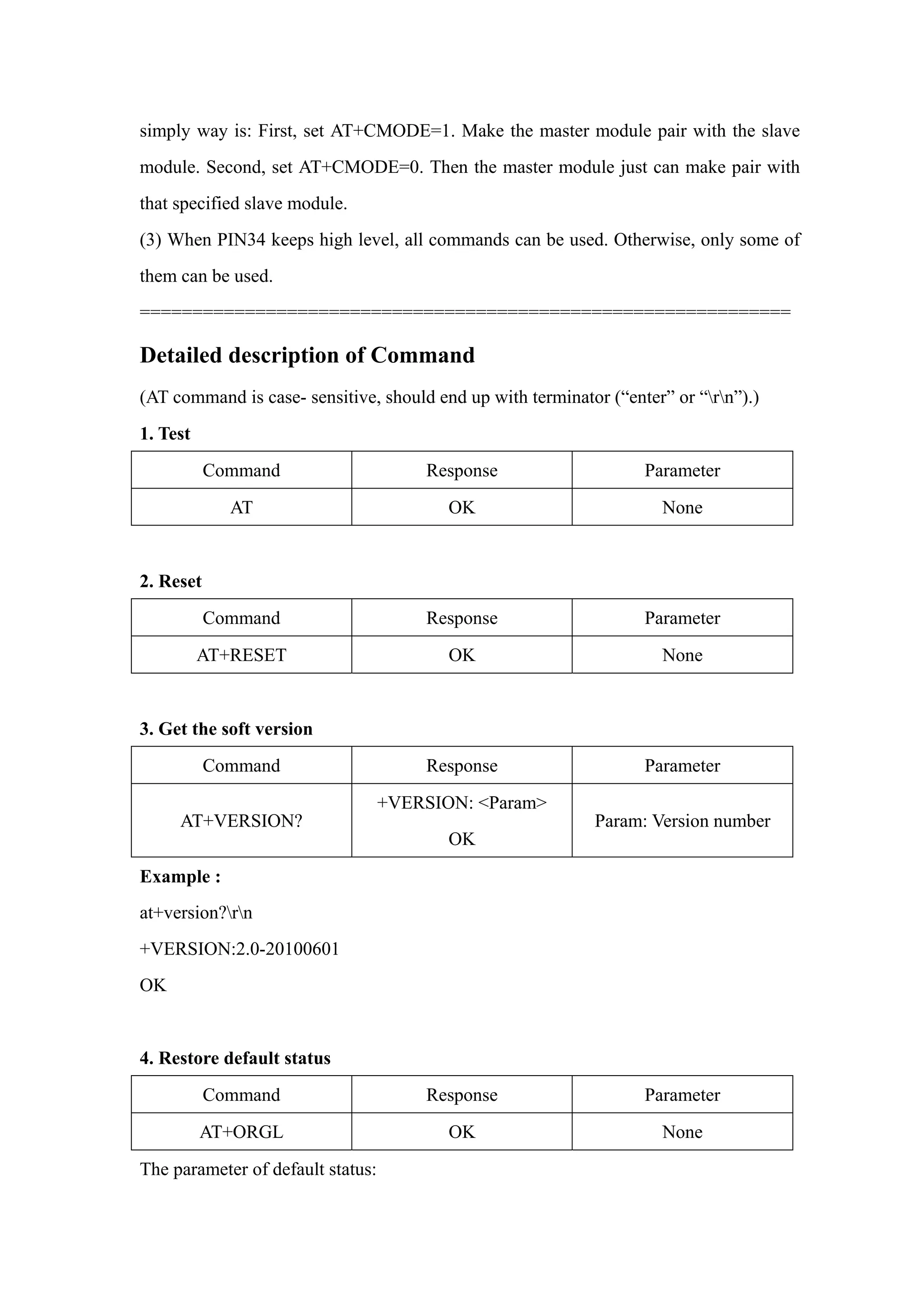
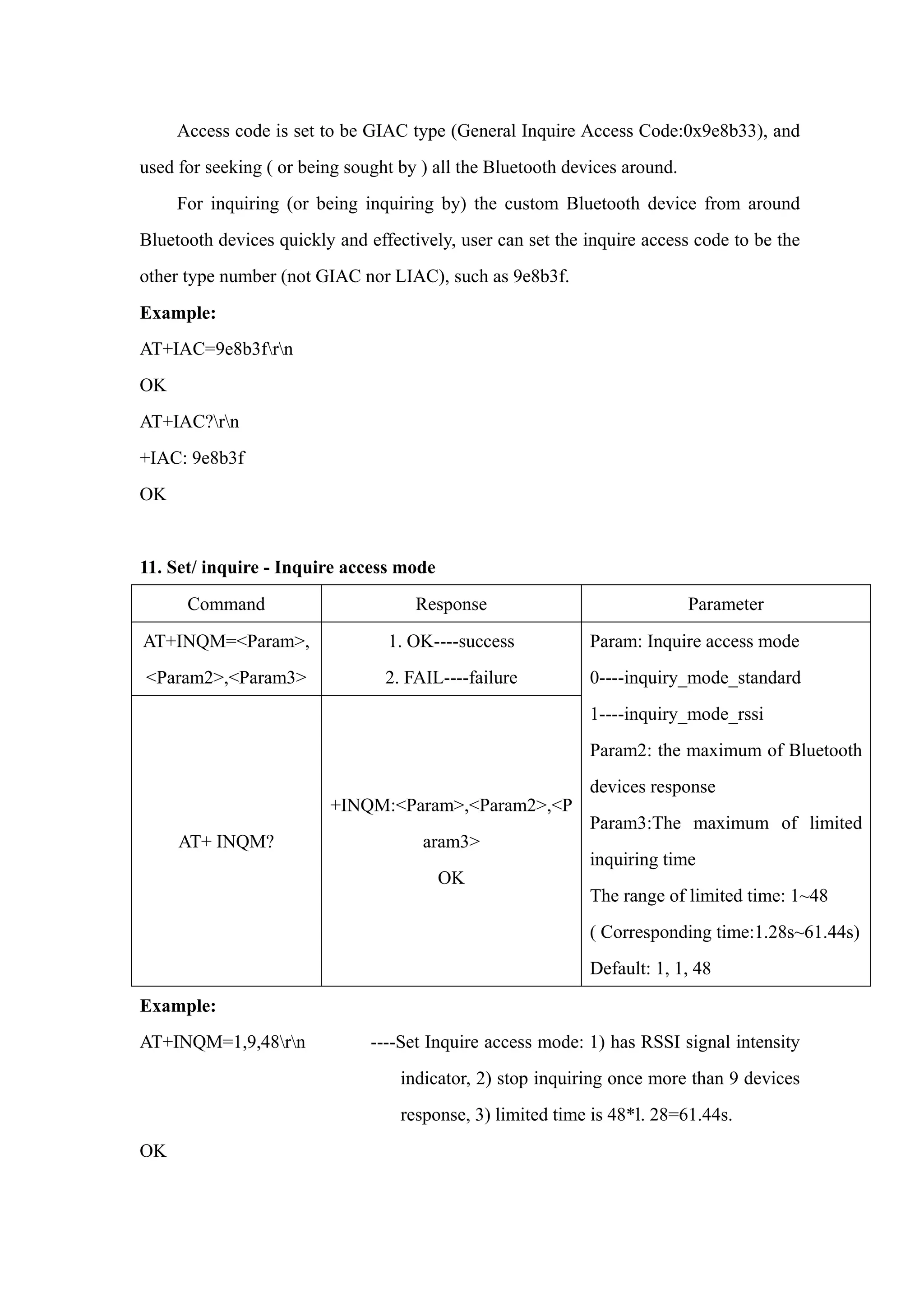
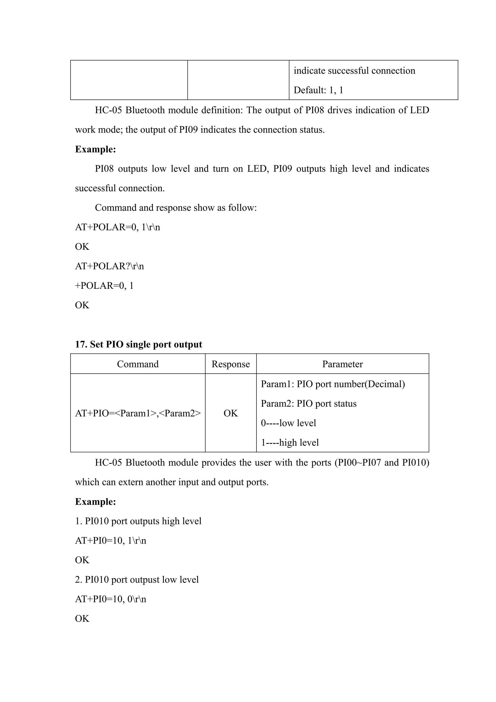
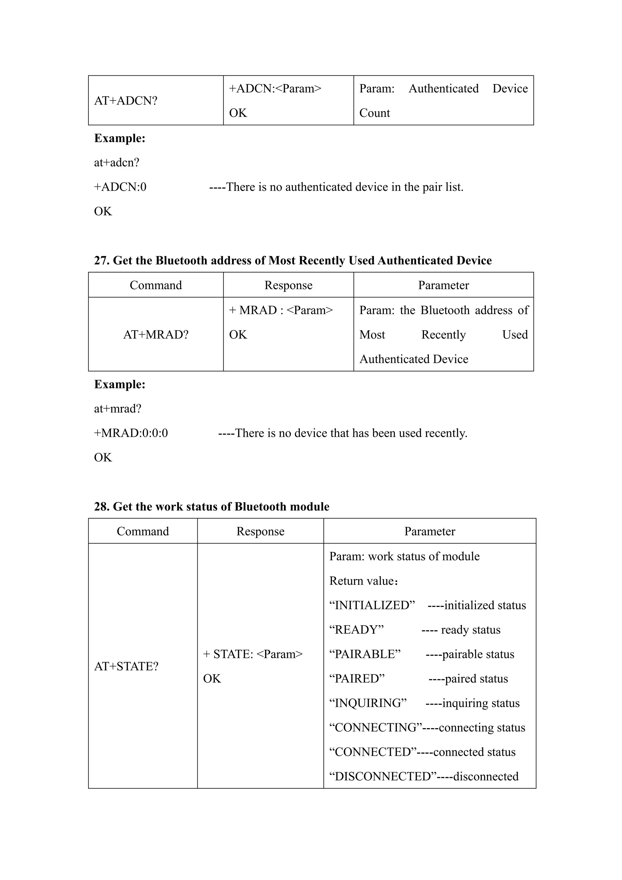
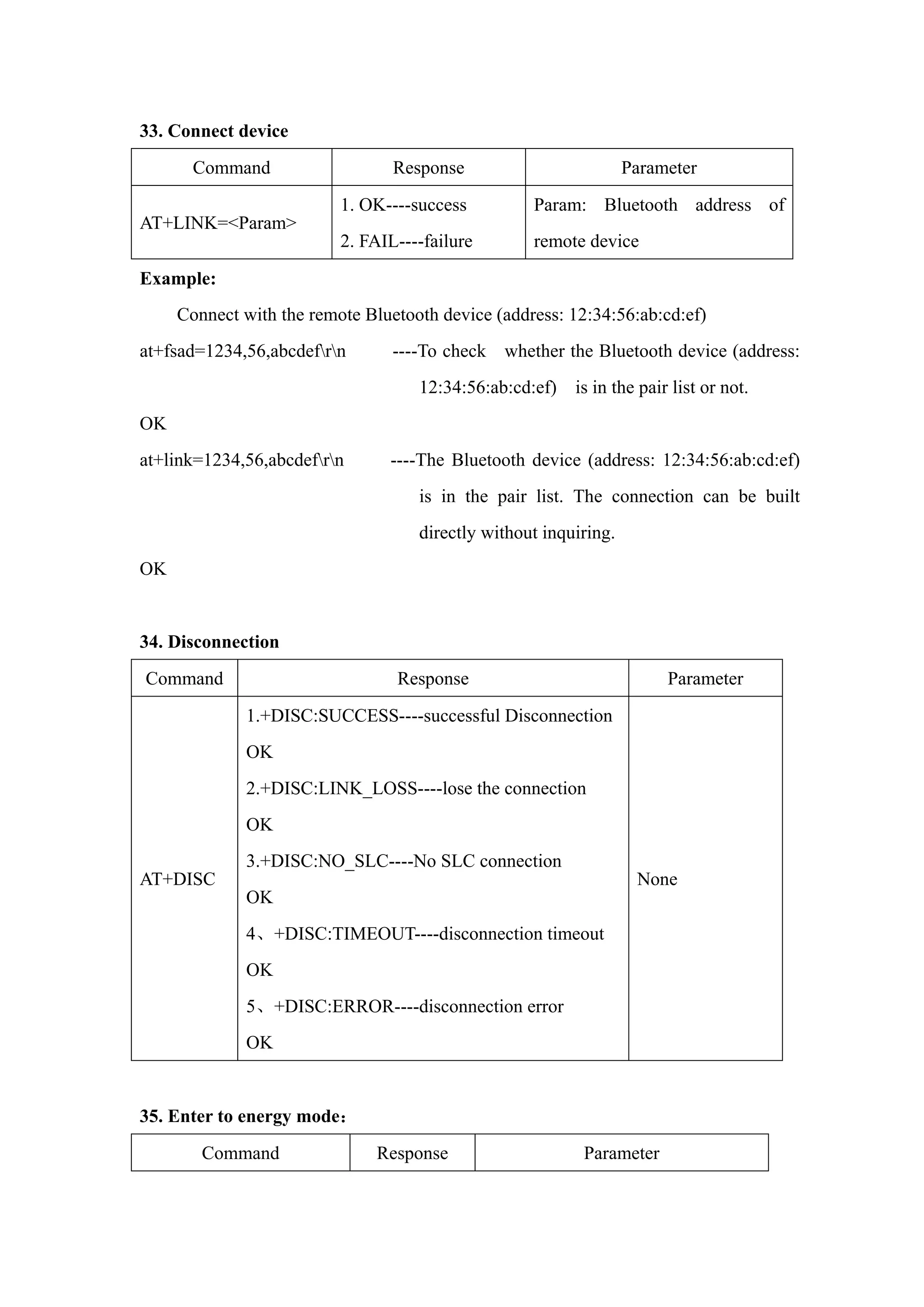
19. Inquire PIO port input
Command Response Parameter
AT+MPIO?
+MPIO: <Param>
OK
Param----PIO port value (16bits)
Param[0]=PI00
Param[1]=PI01
Param[2]=PI02
……
Param[10]=PI010
Param[11]=PI011
HC-05 Bluetooth module provides the user with the ports (PI00~PI07 and PI010)
which can extern another input and output ports.
20. Set/ Inquire page scan and inquire scan parameter
Command Response Parameter
AT+IPSCAN=<Param1>,
<Param2>,
<Param3>,<Param4>AT+I
PSCAN?
OK
+IPSCAN:
<Param1>,<Param2>,
<Param3>,<Param4>
OK
Param1:time interval of
inquiring
Param2: duration in inquiring
Param3: time interval of paging
Param4: duration in paging
The above parameters are
decimal.
Default:1024,512,1024,512
Example:
at+ipscan=1234,500,1200,250rn
OK
at+ipscan?
+IPSCAN:1234,500,1200,250](https://image.slidesharecdn.com/hc-05-atcommandset-150201001201-conversion-gate02/75/Hc-05-at-command-set-13-2048.jpg)

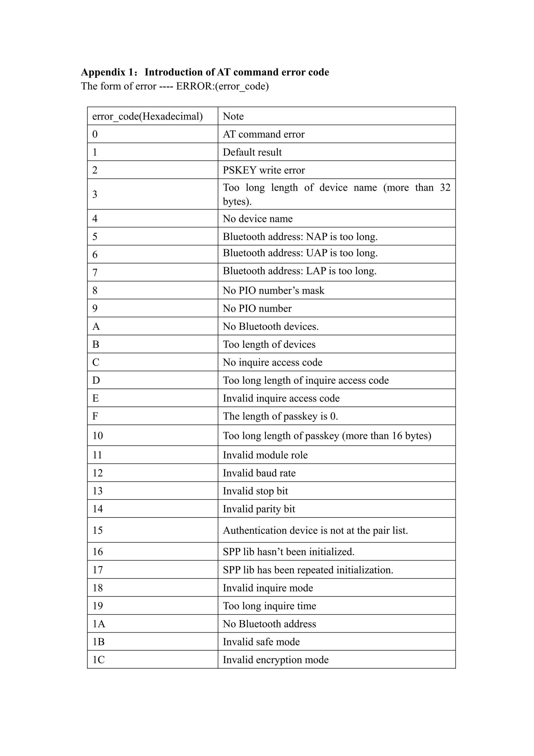
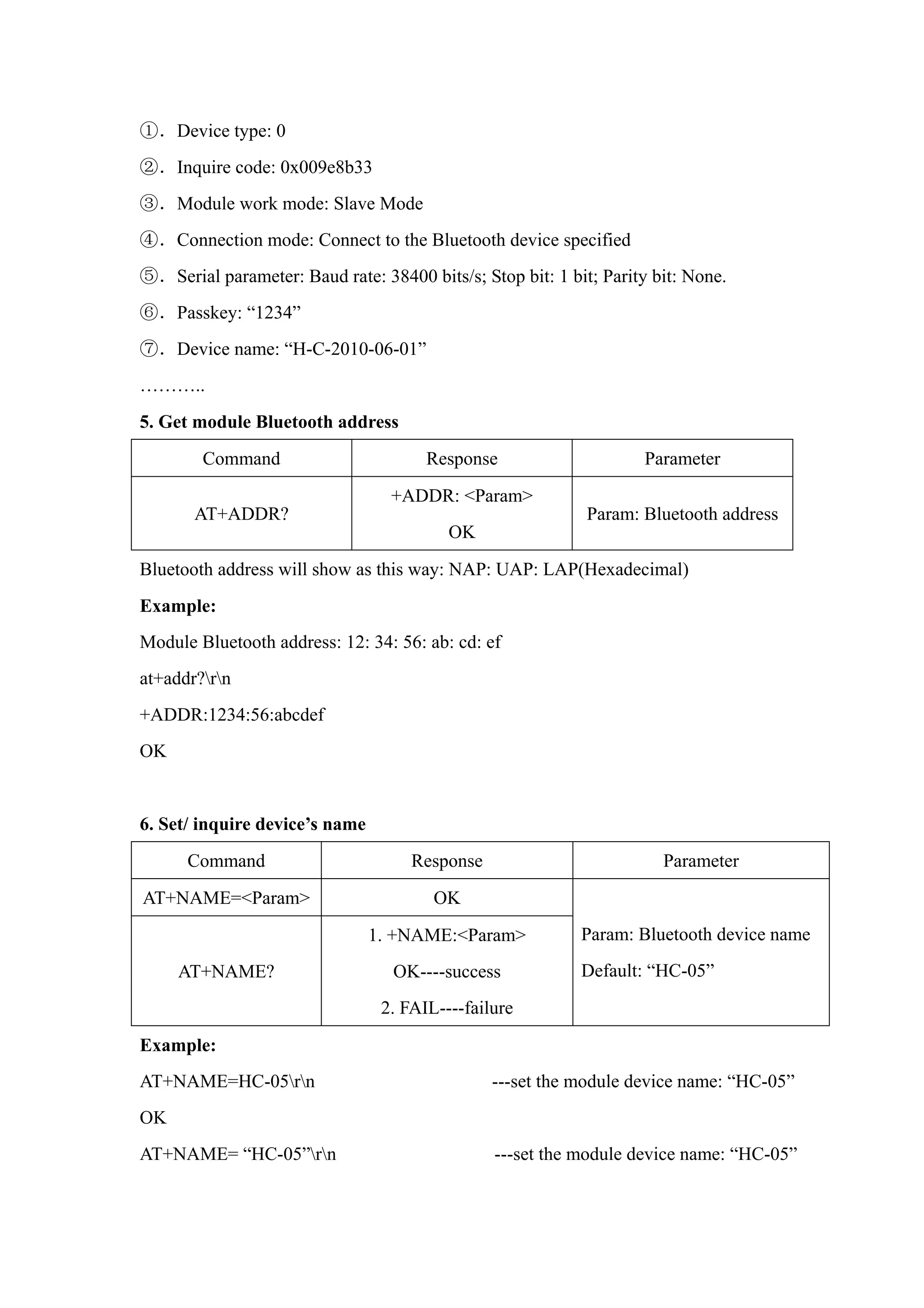
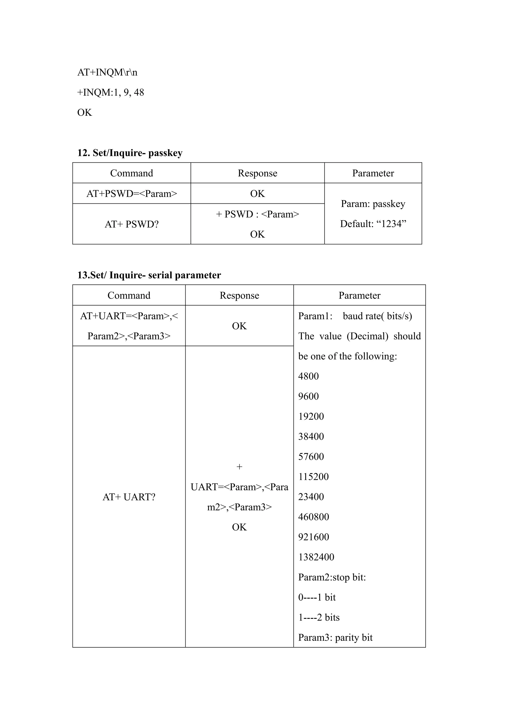
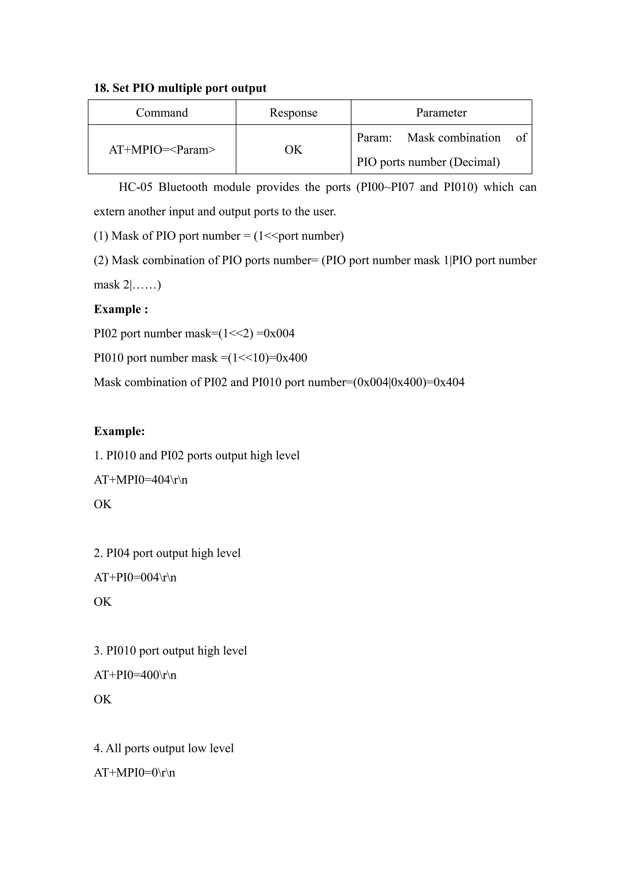
![Appendix 2: The introduction of devices
The Class of Device/Service(CoD) is a 32 bits number that of 3 field specifies the
service supported by the device. Another field specifies the minor device class, which
describes the device type in more detail
The Class of Device /Service (CoD) field has a variable format. The format is
indicated using the ’within the CoD .The length of the Format Type field is variable and
ends with two bits different from’11’.The version field starts at the least significant bit
of the CoD and may extend upwards. In the ’format#1’ of the CoD (format Type field
=00), 11 bits are assigned as a bit –mask (multiple bits can be set) each bit
corresponding to a high level generic category of service class. Currently 7 categories
are defined. These are primarily of a’ public service’ nature. The remaining 11 bits are
used for indicating device type category and other device-specific characteristics. Any
reserved but otherwise unassigned bits, such as in the Major Service Class field, should
be to 0.
Figure 1.2: The Class of Device/Service field (format type). Please note the krder in
which the octets are sent on the air and stored in memory. Bit number 0 is sent first on
the air .
1. MAJOR SERVICE CLASSES
Bit no Major Service Class
13 Limited Discoverable Mode [Ref #1]
14 (reserved)
15 (reserved)
16 Positioning(Location identification)
17 Networking (LAN, Ad hoc, … )
18 Rendering (Printing ,Speaker,…)
19 Capturing (Scanner, Microphone,…)
20 0bject Transfer (v-Inbox, v-Folder,…)
21 Audio (Speaker, Microphone, Headset service,…)](https://image.slidesharecdn.com/hc-05-atcommandset-150201001201-conversion-gate02/75/Hc-05-at-command-set-23-2048.jpg)
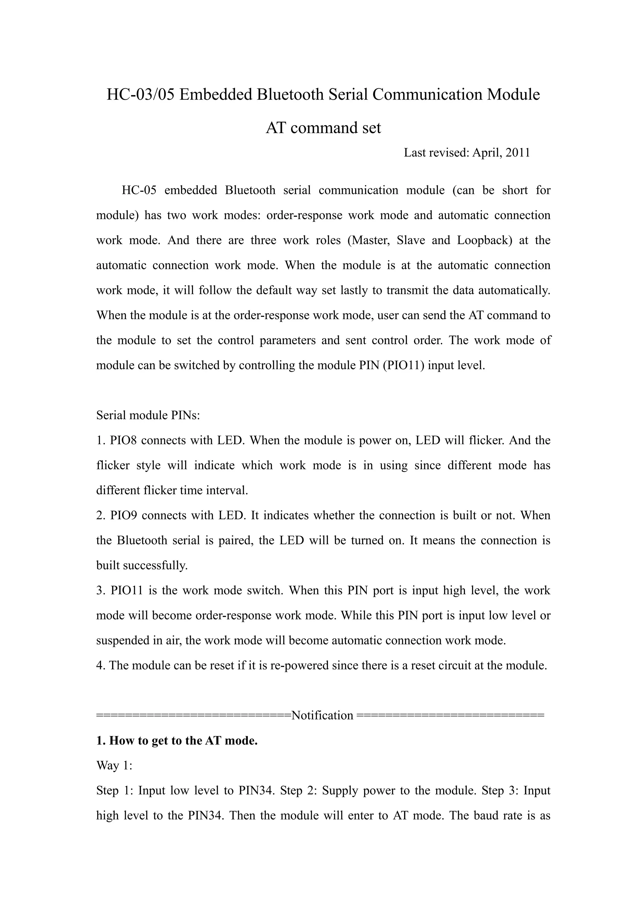
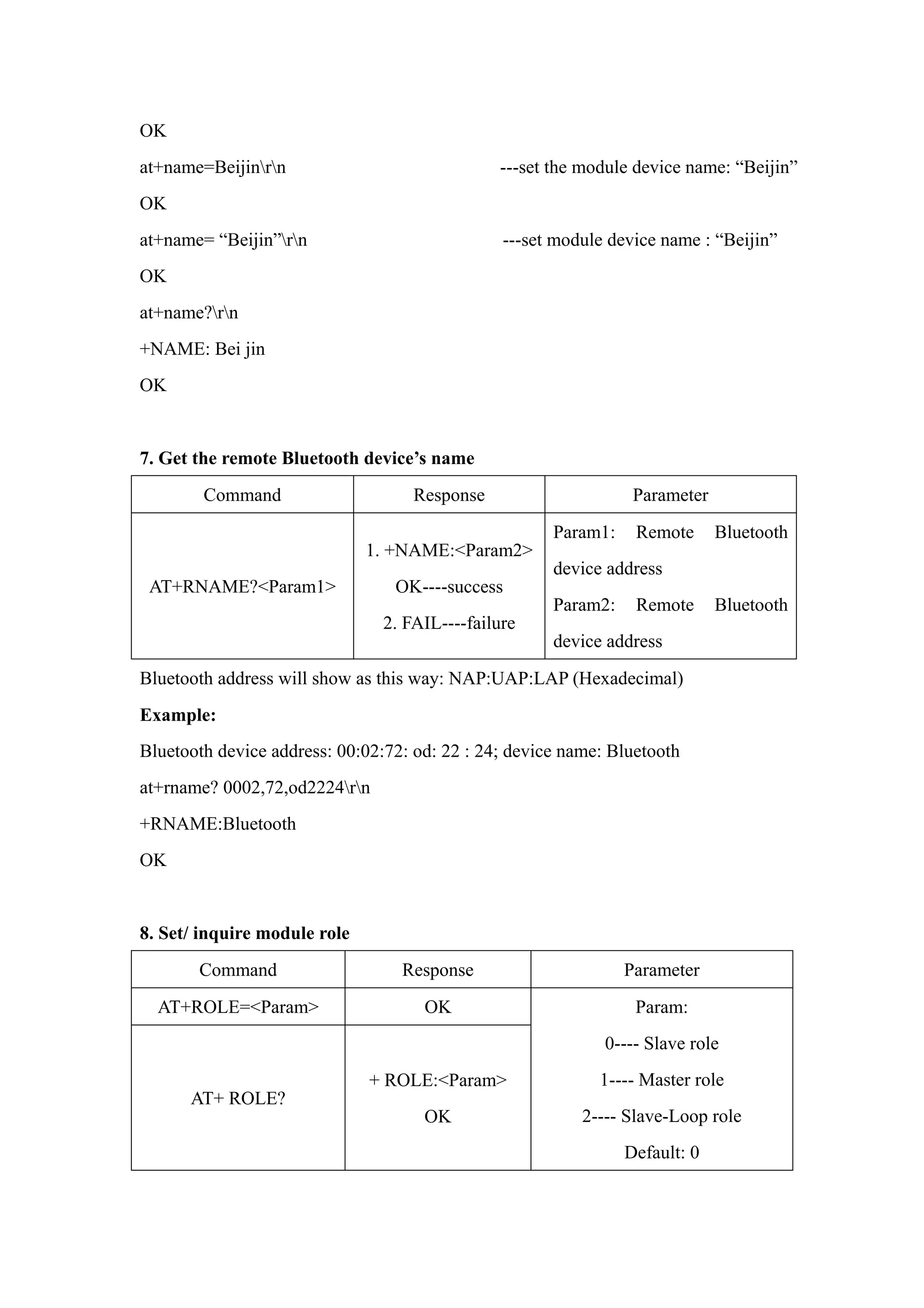
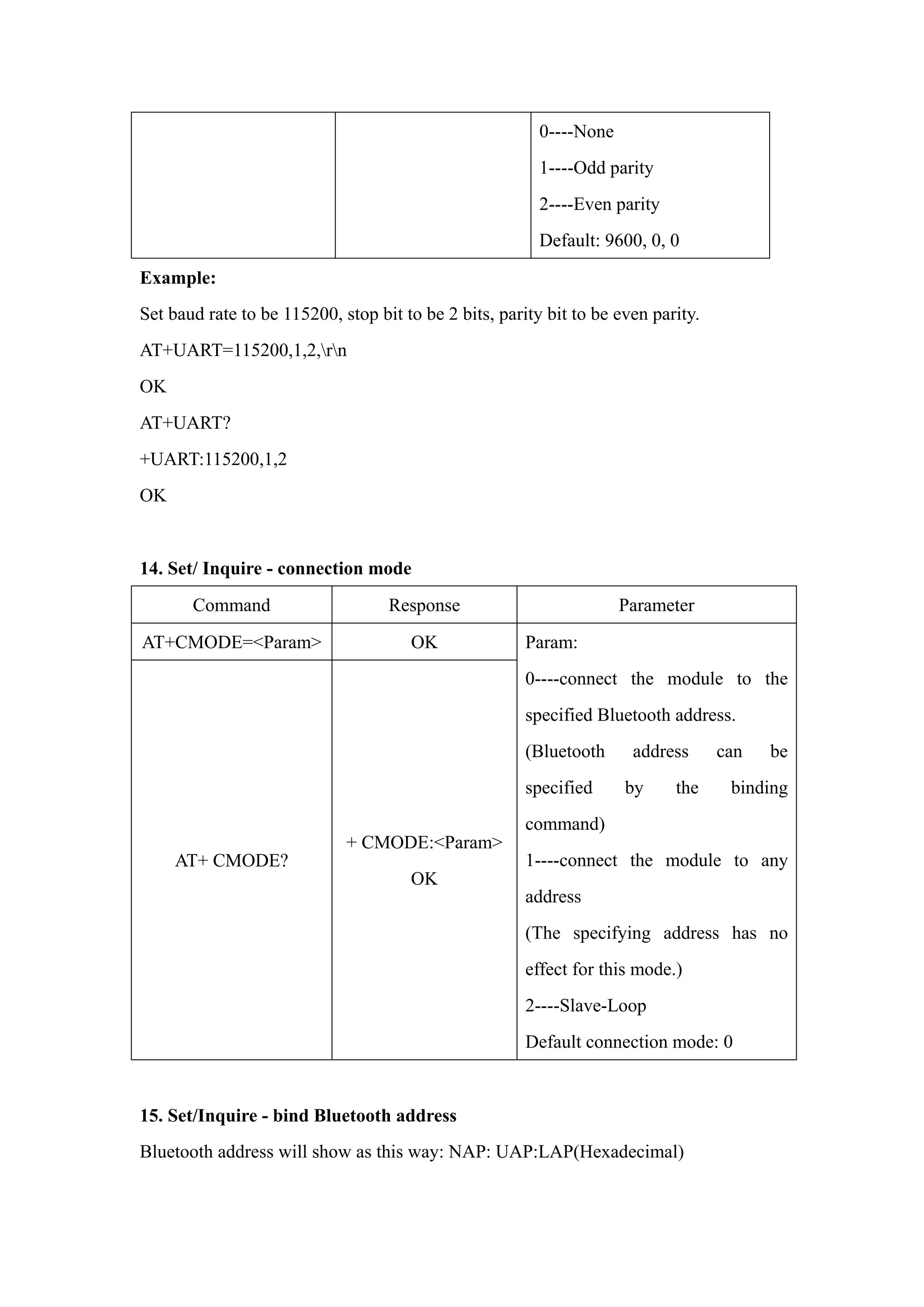
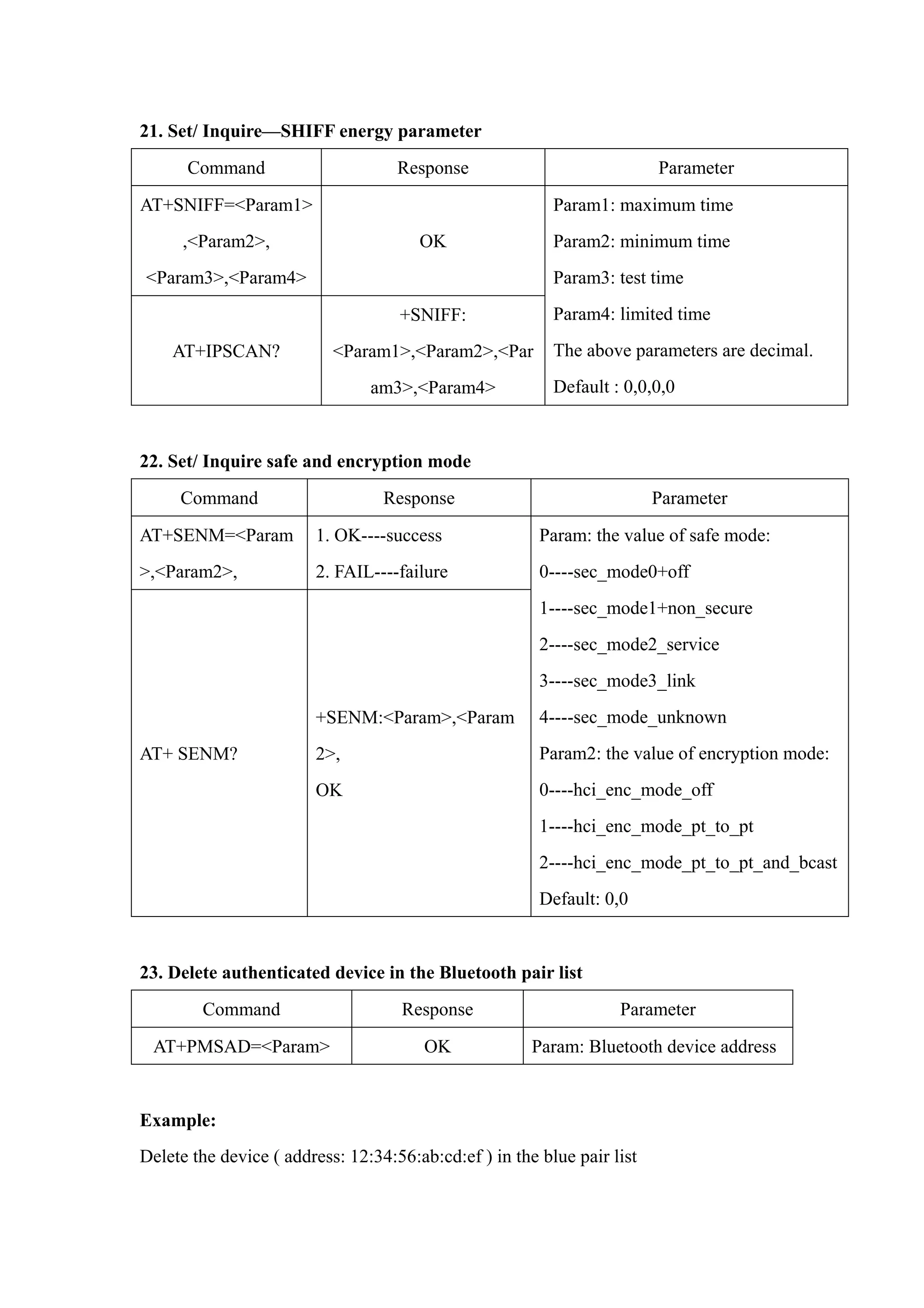
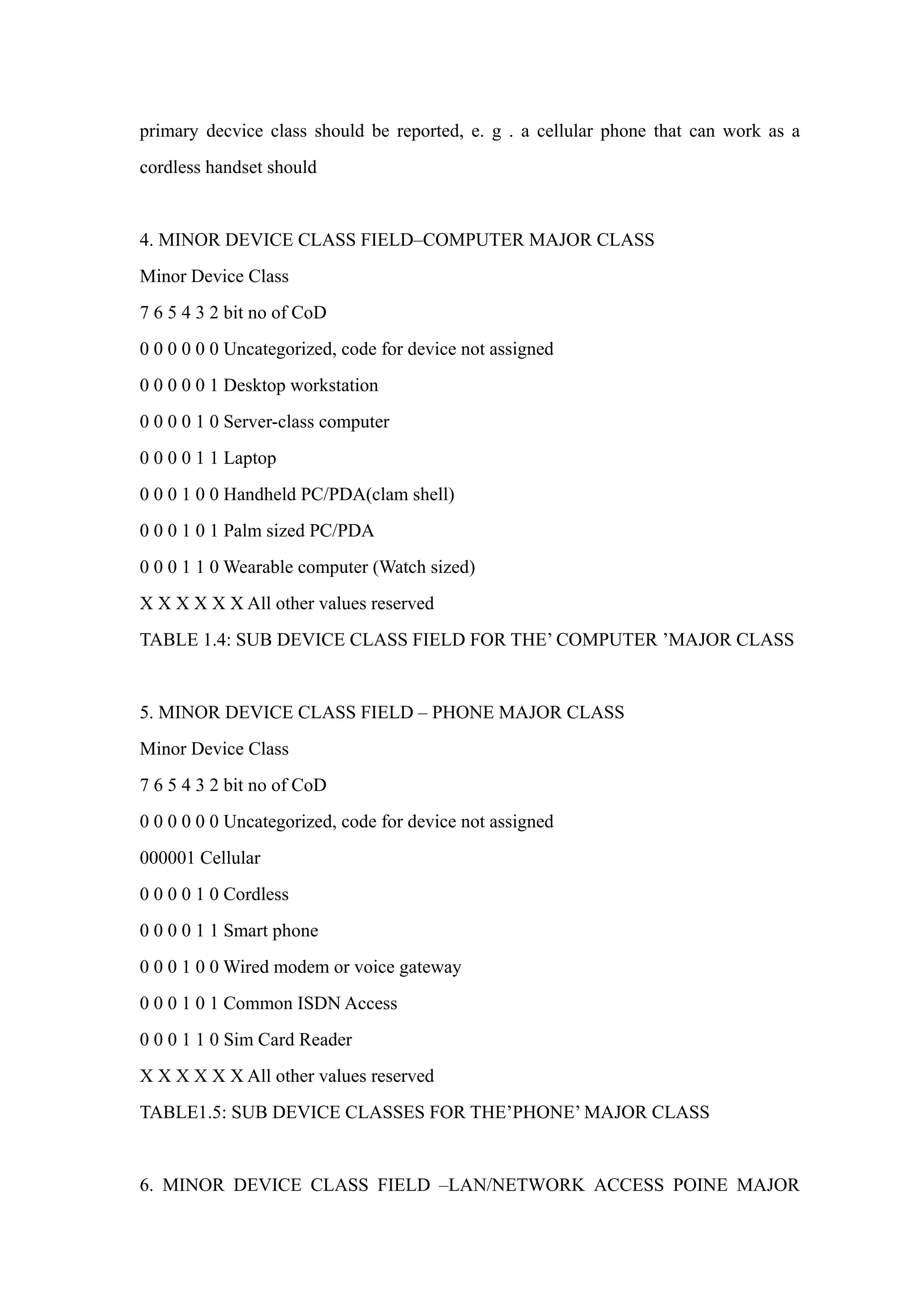
![22 Telephony (Cordless telephony, Modem, Headset service,…)
23 Information (WEB-server, WAP- server,…)
TABLE 1.2:MAJOR SERVICE CLASSES
[Ref #1 As defined in See Generic Access Profile, Bluetooth SIG]
2. MAJOR DEVICE CLASSES
The Major Class segment is the highest level of granularity for defining a
Bluetooth Device. The main function of a device is used for determining the major
Class grouping. There are 32 different possible major classes. The assignment of this
Major Class field is defined in Table1.3.
1 2 1 1 1 0 9 8 Major Device Class
0 0 0 0 0 Miscel laneous [Ref #2]
0 0 0 0 1 Computer (desktop, notebook, PDA, organizers,…)
0 0 0 1 0 Phone (cellular ,cordless ,payphone, modem,…)
0 0 0 1 1 LAN/Network Access point
0 0 1 0 0 Audio/Video (headset, speaker, stereo, video display, vcr …)
0 0 1 0 1 Periphereal (mouse, joystick, keyboards.…)
0 0 1 1 0 Imaging (printing, scanner, camera, display,…)
1 1 1 1 1 Uncategorized, specific device code not specified
X X X X All other values reserved
TABLE 1.3: MAJOE DEVICE CLASSES
[Ref #2:Used where a more specific Major Device Class is not suited (but only as
specified as in this document) .Devices that do not have a major class assigned can use
the all-1 code until’ classified’]
3. THE MINOR DEVICE CLASS FIELD
The’ Minor Device Class field’ (bits 7 to 2 in the CoD ), are to be interpreted only
in the context of the Major Device Class (but interpreted of the Service Class field).
Thus the meaning of the bits may change, depending on the value of the ’ Major Device
Class field’. When the Minor Device Class field indicates a device class ,then the](https://image.slidesharecdn.com/hc-05-atcommandset-150201001201-conversion-gate02/75/Hc-05-at-command-set-24-2048.jpg)
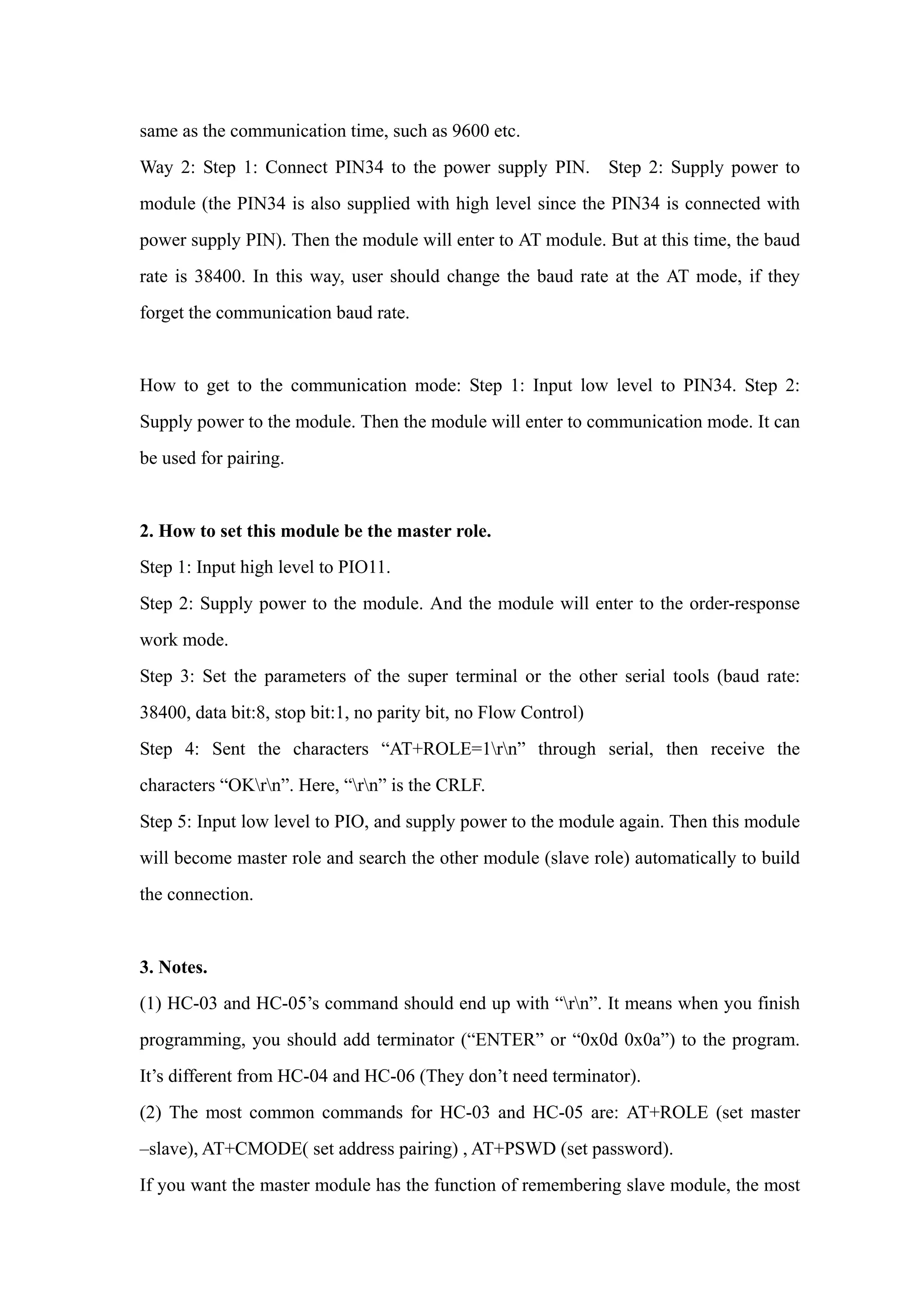
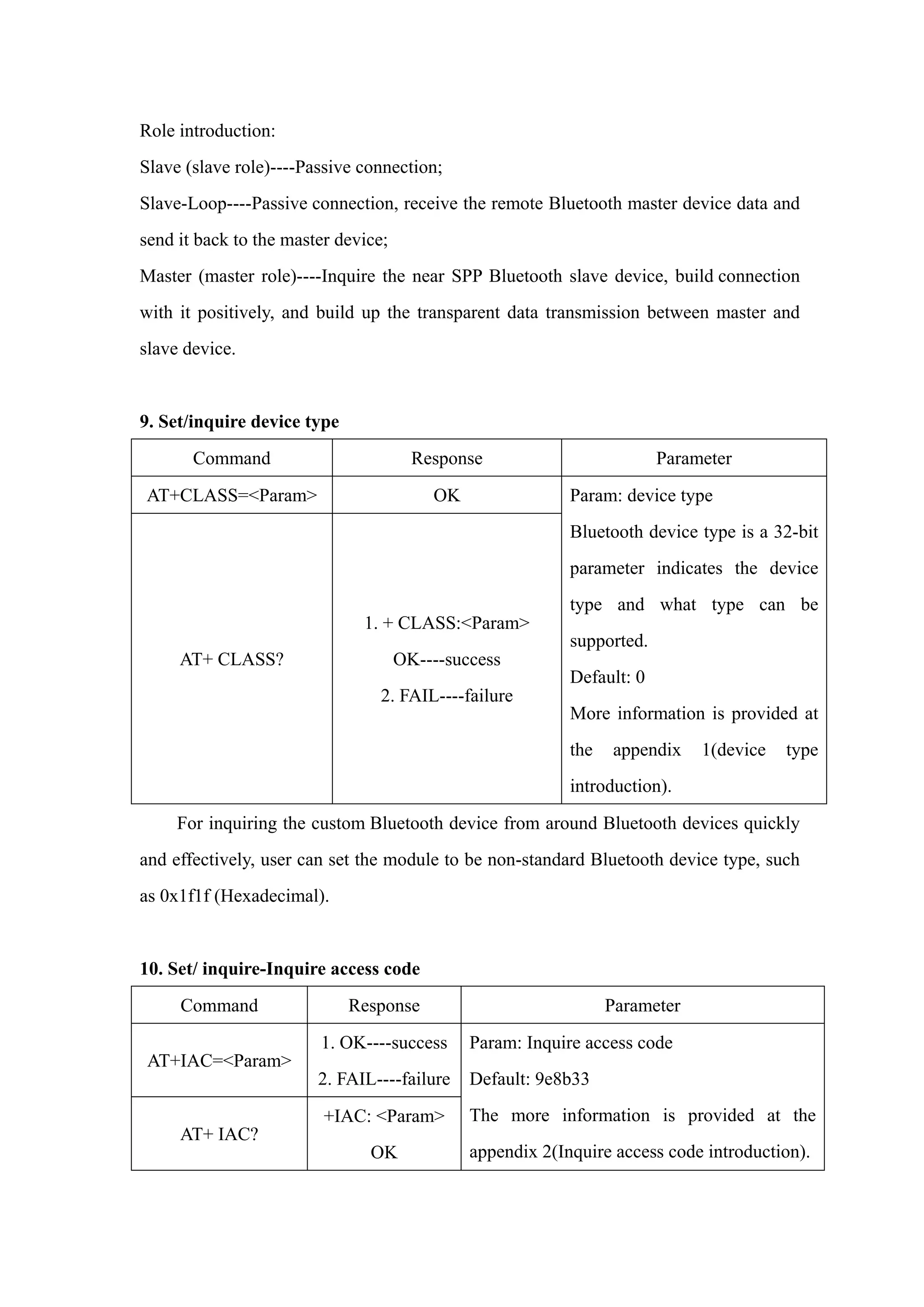
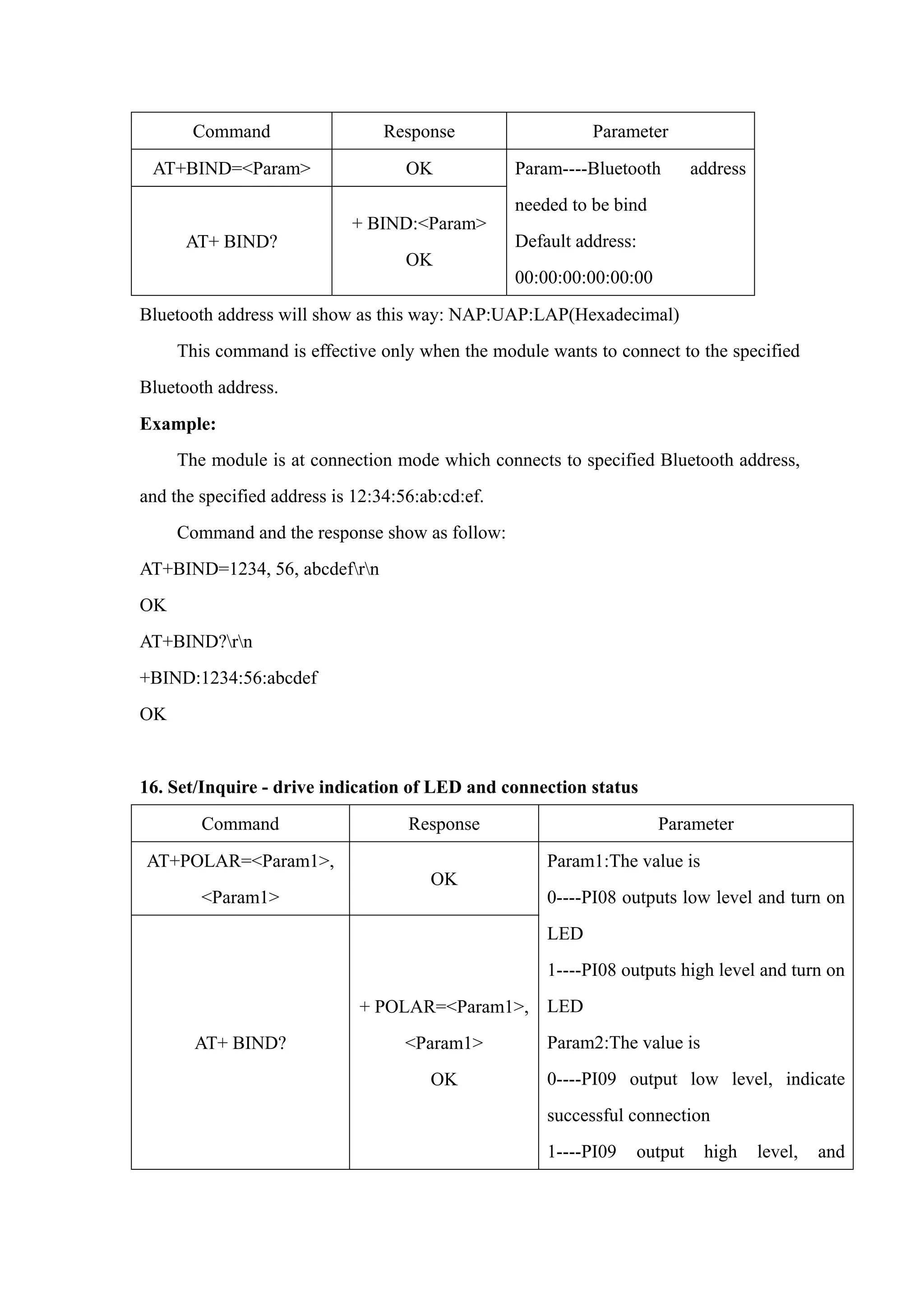
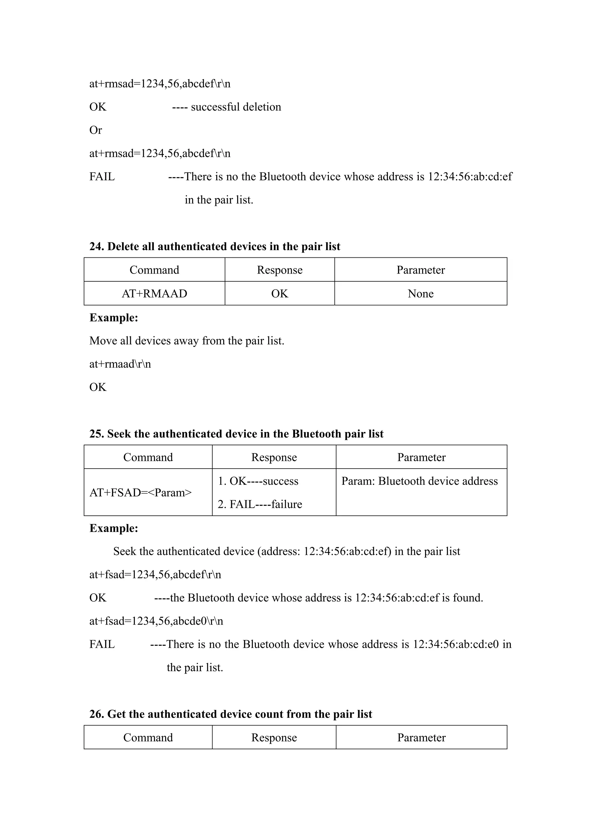
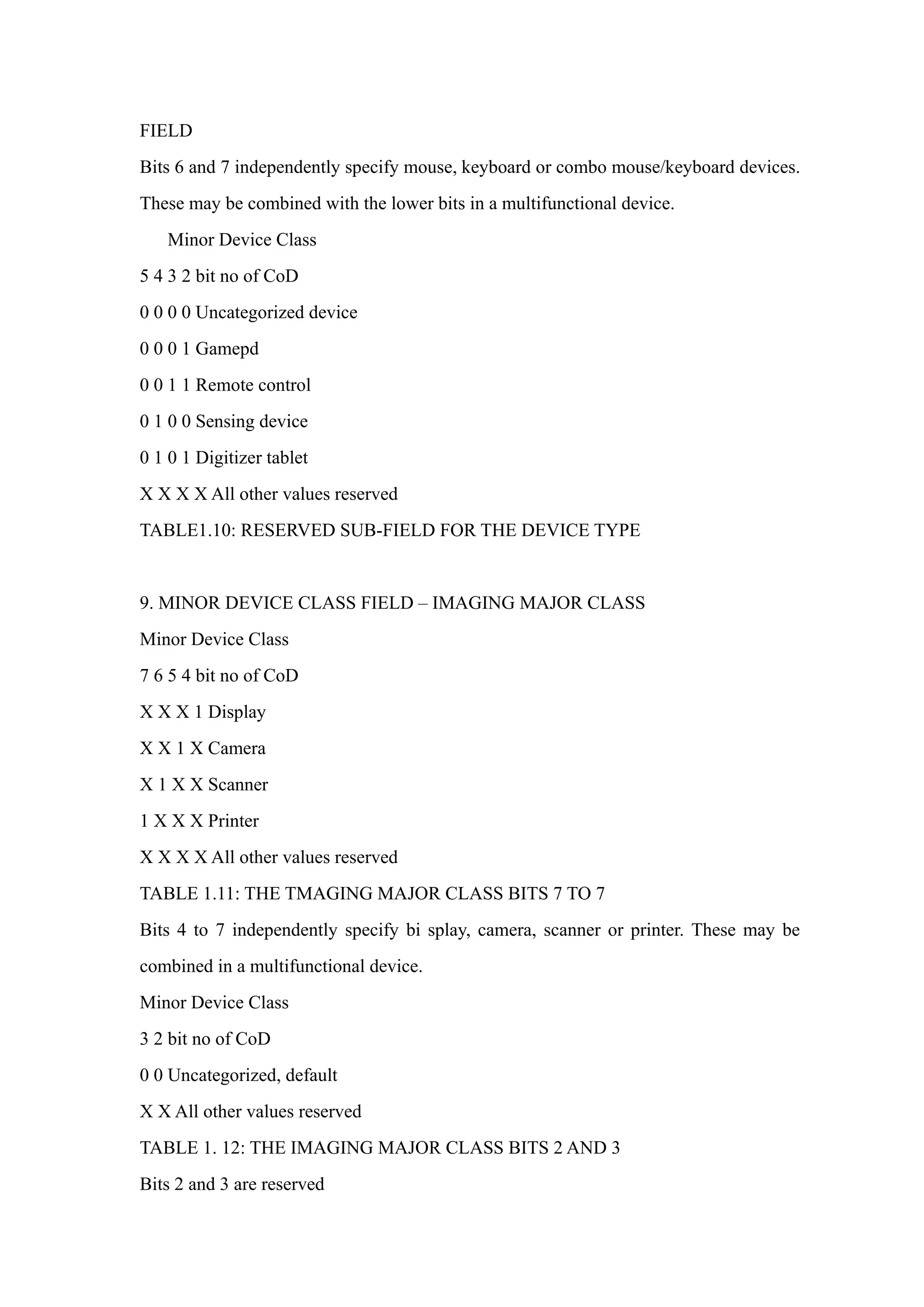
![CLASS
Minor Device Class
7 6 5 bit no of CoD
0 0 0 Fully available
0 0 1 1 – 17% utilized
0 1 0 1 7 - 33% utilized
0 1 1 3 3 – 50% utilized
1 0 0 5 0 – 67% utilized
1 0 1 6 7 – 83% utilized
1 1 0 8 3 – 99% utilized
1 1 1 No service available [REF #3]
XXX All other values reserved
TABLE1.6: THE LAN/NETWORK ACCESS POINE LOAD FACTOR FIELD
[Ref #3:“Device is fully utilized and cannot accept additional connections at this time,
please retry later”]
The exact loading formula is not standardized. It is up to each LAN/Network
Access Point implementation to determine what internal conditions to report as a
utilization of communication requirement is that the box .As a recommendation, a client
that locates multiple LAN/Network Access Points should attempt to connect to the one
reporting the lowest load.
Minor Device Class
4 3 2 bit no of CoD
0 0 0 Uncategorized (use this value if no other apply )
XXX All other values reserved
TABLE1.7:RESERVED SUB-FIELD FOR THE LAN/NETWORK ACCESS POINE
7. MINOR DEVICE CLASS FIELD – AUDIO/VIDEO MAJOR CLASS
Minor Device Class
7 6 5 4 3 2 bit no of CoD
0 0 0 0 0 0 Uncategorized, code not assigned](https://image.slidesharecdn.com/hc-05-atcommandset-150201001201-conversion-gate02/75/Hc-05-at-command-set-26-2048.jpg)
![0 0 0 0 0 1 Device conforms to the Headset profile
000010 Hands-free
0 0 0 0 1 1 (Reserved )
0 0 0 1 0 0 Microphone
0 0 0 1 0 1 Loudspeaker
0 0 0 1 1 0 Headphones
0 0 0 1 1 1 Portable Audio
0 0 1 0 0 0 Car audio
0 0 1 0 0 1 Set-top box
0 0 1 0 1 0 HiFi Audio Device
001011 VCR
0 0 1 1 0 1 Camcorder
0 0 1 1 1 0 Video Monitor
0 0 1 1 1 1 Video Display and Loudspeaker
0 1 0 0 0 0 Video Conferencing
0 1 0 0 0 1 (Reserved)
0 1 0 0 1 0 Gaming/Toy [Ref #4]
X X X X X X All other values reserved
[Ret #4: Only to be used with a Gaming/Toy device that makes audio/video capabilities
available via Bluetooth]
TABLE 1.8: SUB DEVICES FOR THE ’AUDIO/VIOEO’MAJOR CLASS
8. MINOR DEVICE CLASS FIELD – PERIPHERAL MAJOR CLASS
Minor Device Class
7 6 bit no of CoD
0 1 Keyboard
1 0 Pointing device
1 1 Combo keyboard /pointing device
X X X All other values reserved
TABLE1.9: THE PERIPHERAL MAJOR CLASS KEYBOARD/POINTING DEVICE](https://image.slidesharecdn.com/hc-05-atcommandset-150201001201-conversion-gate02/75/Hc-05-at-command-set-27-2048.jpg)

The document describes the AT command set for the HC-03/05 embedded Bluetooth serial communication module. It has two main modes - order-response mode and automatic connection mode, with three roles in automatic connection mode: Master, Slave, and Loopback. The module's mode can be switched by controlling the PIO11 pin level. It provides various AT commands to control parameters like role, address, name, baud rate. Commands need to end with a terminator. PIO pins have functions like controlling the LED and reset.