Downloaded 15 times
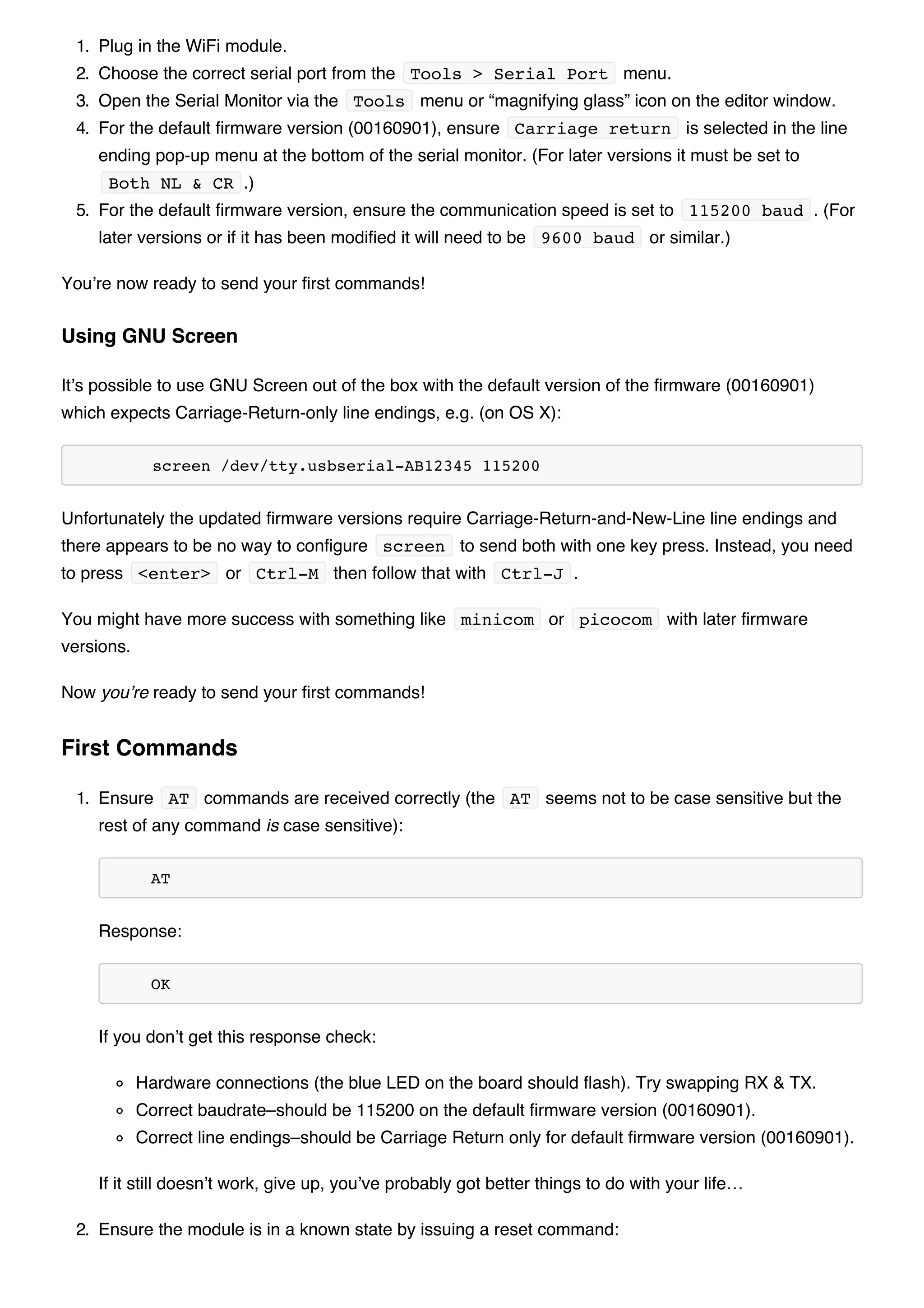
![KiwiconAte!
The module should display the following ( 0 being the connection channel, 13 being the length
of the data received:
+IPD,0,13:KiwiconAte!
OK
You can send data in response with the CIPSEND command as used previously, e.g. ( 0 is the
channel, 8 is the length of the data):
AT+CIPSEND=0,8
The module will display the prompt:
>
Then you can send the data, e.g.:
WhatEvs
And then the module will respond with:
SEND OK
The telnet session should now display:
WhatEvs
You can then end the telnet session with by pressing Ctrl-] and q<enter> , the module will
display:
Unlink
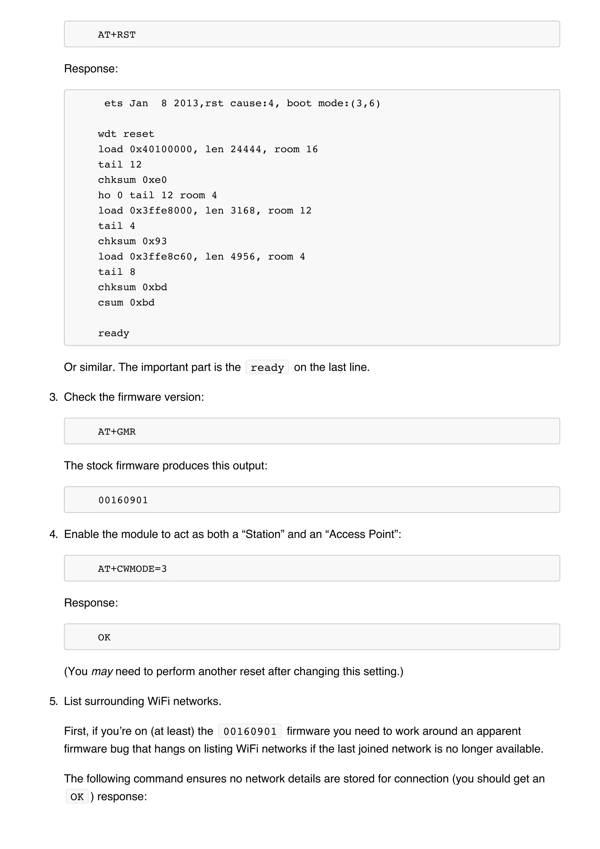
In addition to connecting to WiFi Access Points the module can also act as an Access Point–this means
you can connect devices to the module without any other network infrastructure in place. Ideal for a
local private shared “drop box” perhaps…
1. The module comes with an access point pre-defined (SSID of “ESP_…”) but you can define your
own with:
AT+CWSAP="NoWorriESSID","password",3,0
The first parameter is the SSID name; the second parameter is the password; the third the WiFi
Acting as a WiFi Access Point](https://image.slidesharecdn.com/esp8266wifimodulequickstartguidev1-151001055353-lva1-app6892/75/Esp8266-wi-fi_module_quick_start_guide_v_1-0-4-10-2048.jpg)
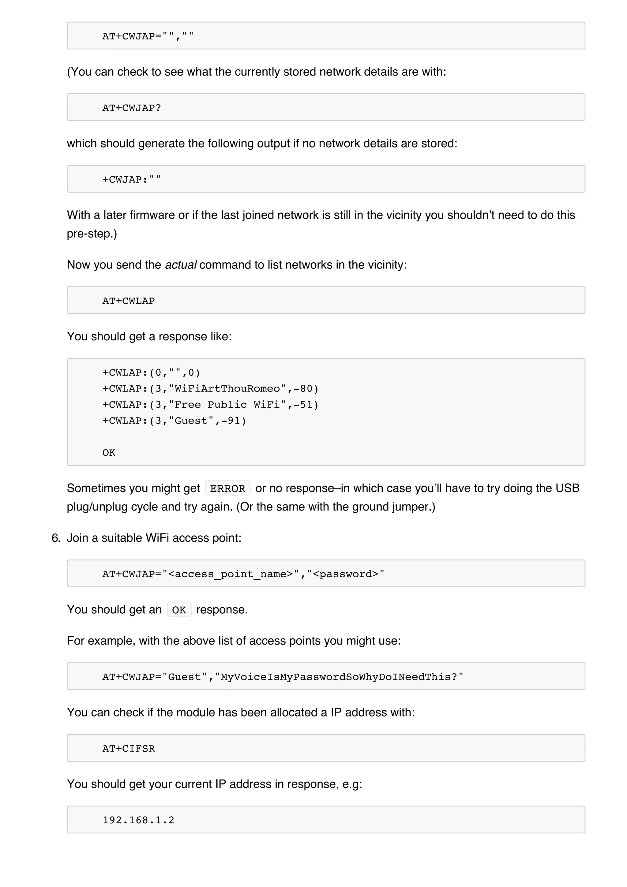
![channel–pick one not used in your area; and, the final parameter is the encryption standard to use.
An encryption value of 0 turns encryption off which means the password is ignored–but it still
can’t be an empty value. I couldn’t get any encryption to work though (it would always create an
unencrypted network) you might have more luck–possibly with a more recent firmware…
2. To actually enable the network to be created you need to set the “WiFi mode” of the module to “AP”
( 2 ) or “Both” ( 3 ):
AT+CWMODE=3
Now you will be able to connect to your module as an access point from another device (e.g. a
laptop or a phone).
3. You can list the IP address etc of any device connected to the network with:
AT+CWLIF
Which generates the response:
192.168.4.100, [...]
4. Now you can run the server example from above and connect–note that the module always has the
IP 192.168.4.1 when acting as an AP.
You’ll be pleased to know you’re not stuck with the ample list of features that ship with your module, no,
because you can update the firmware of your module! Yes, that means you can get new features & new
bugs too…
It’s not particularly easy to find new official firmware versions–the links are spread over forums, wikis
and Google Drive accounts which don’t look particularly legit.
It seems like the best source of details is the “Updates” section of the “Firmware” section on this page:
http://www.electrodragon.com/w/Wi07c#Firmware
This ridiculous URL (from the link entitled “Find most upated firmware on this google link” on the above
ElectroDragon page) seems to list all the official firmware updates: https://drive.google.com/folderview?
id=0B3dUKfqzZnlwR2pVWjg3NXRVdW8&usp=drive_web&tid=0B3dUKfqzZnlwRjFaNTUzZFptbzg#list
Consider uploading one of the following versions:
ESP8266_flasher_V00170901_00_Cloud Update Ready.zip
ESP8266_AT_V00180902_02_baudrate watchdog added.zip
(A note on version numbers: the version number 00160901 is made up of two parts: 0016 is the
Updating the firmware
Finding New Official Firmware](https://image.slidesharecdn.com/esp8266wifimodulequickstartguidev1-151001055353-lva1-app6892/75/Esp8266-wi-fi_module_quick_start_guide_v_1-0-4-11-2048.jpg)


The document provides an overview of connecting and communicating with an ESP8266 WiFi module via serial. It discusses the hardware connections needed, including using an FTDI or Arduino board. It then demonstrates some basic AT commands to check the module status, list available networks, connect to a network, and act as both a TCP client and server.


![Introduction to ESP32 Programming [Road to RIoT 2017]](https://cdn.slidesharecdn.com/ss_thumbnails/roadtoriotsurabayagettingstartedesp32-170726155154-thumbnail.jpg?width=640&height=640&fit=bounds)