Download to read offline
![W1
L13
L2
L9
L9
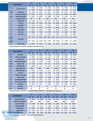
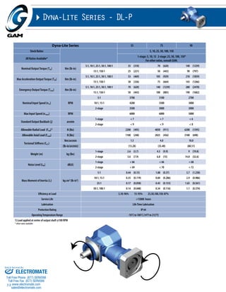
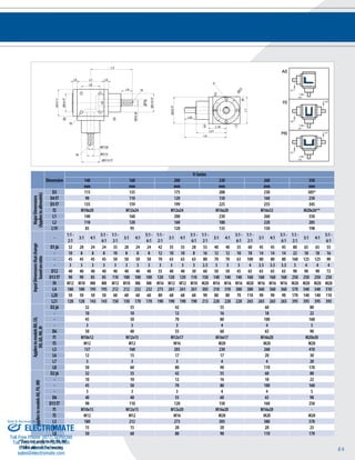
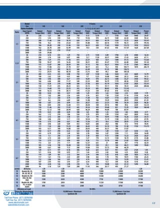
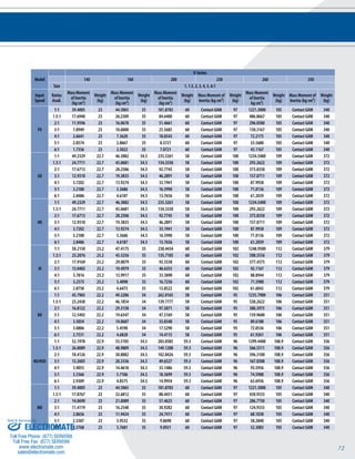
Example: DS - W B - 090 - 005 G - [115-201] - S111
Gearbox Series
DS = Dyna Series
DSX = Dyna Series Extreme
Sold & Serviced By:
53
Dyna Series - DS-W, DS-H, DS-T, DS-F
f1
Recommended Output Coupling (if necessary)
D3 g6
L5 L1 L5
metal bellows KM-60 KM-170 KM-270 KM-400 KM-1300 KSD-2500
elastomer EKM-60 EKM-150 EKM-300 EKM-500 EKM-1000 -
Tolerances (mm)
Size k6 g6 h8 f7 H7 h6
Over 6 +0.010 -0.005 0 -0.013 +0.015 0
Thru 10 +0.001 -0.014 -0.022 -0.028 0 -0.009
Over 10 +0.012 -0.006 0 -0.016 +0.018 0
Thru 18 +0.001 -0.017 -0.027 -0.034 0 -0.011
Over 18 +0.015 -0.007 0 -0.02 +0.021 0
Thru 30 +0.002 -0.020 -0.033 -0.041 0 -0.013
Over 30 +0.018 -0.009 0 -0.025 +0.025 0
Thru 50 +0.002 -0.025 -0.039 -0.05 0 -0.016
Over 50 +0.021 -0.010 0 -0.03 +0.030 0
Thru 80 +0.002 -0.029 -0.046 -0.06 0 -0.019
Over 80 +0.025 -0.012 0 -0.036 +0.035 0
Thru 120 +0.003 -0.034 -0.054 -0.021 0 -0.022
Over 120 +0.028 -0.014 0 -0.043 +0.040 0
Thru 180 +0.003 -0.039 -0.063 -0.083 0 -0.025
Special Options
Assigned by GAM
Motor Mount Kit
Assigned by GAM
LOW OUTPUT
TYPE CODES FOR DYNA SERIES
OPTION BACKLASH KEYWAY
A= Y N
C= Y Y
G= N Y
H= N N
Gearbox Style
W = Single output shaft
T = Dual output shaft
H = Hollow output shaft
F = Flange output
Input Type
B = Bellows coupling input
E = Elastomer coupling input
L = Shaft input
Gearbox Size
055, 075, 090, 115, 130, 140, 160, 190
Options Available for This Product
Ratio
003, 004, 005, 006, 008, 010,
012, 015, 030, 040, 050, 070, 100
Options C and G N/A for DS-F/H models.
Contact GAM for DSX Drawings
DS-F
L20
D12 H7
D11 h8
L21
L19
f2
W2
D7 H7
D8
L13
L2
L15
L2
DS-H
L12
D4 H7
L4
L7
D5 f7
D4 H7
L6
L13 L13
L18
L14
L11
D1
L13 L5 L1
L10
D3 g6
L5
L14
L2
L13
D8
L13 L13
L10
D2 k6
D2 k6
DS-T
L16
L3
L8
L3
L8
f3
DS-W
D2 k6
D9 k6
L17 f1
L15
L3
f3
L9
L8
L12
L12
L11
D1
ELECTROMATE
Toll Free Phone (877) SERVO98
Toll Free Fax (877) SERV099
www.electromate.com
sales@electromate.com](https://image.slidesharecdn.com/gamrightanglegearreducerscatalog-141001201725-phpapp02/85/Gam-right-angle_gear_reducers_catalog-5-320.jpg)
![58
Ø D4
L10
Ø D6 H7
Ø D7
f2
Ø D1
L1
L8
L4
L9
L5 L3
L6
Ø D5
L7
L2
Ø D2 k6
Ø D3 g6
Ø D6 H7
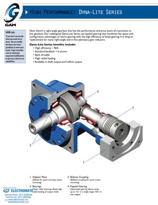
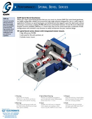
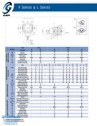
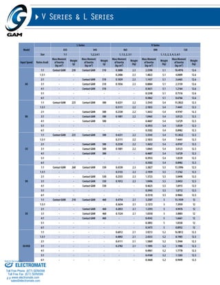
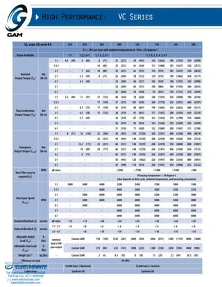
DL-DW DL-DH
DL - DW and DL - DH
55 75 90
mm (in) mm (in) mm (in)
D1 max (1 stage)* motor shaft diameter 16 (0.63) 20 (0.787) 35 (1.378)
D1 max (2 stage standard)* motor shaft diameter 14 (0.551) 19 (0.748) 19 (0.748)
D1 max (2 stage available)* motor shaft diameter 16 (0.63) 24 (0.945) 24 (0.945)
D2 k6 output shaft diameter 20 (0.787) 24 (0.945) 32 (1.26)
D3 g6 pilot diameter 89 (3.504) 105 (4.134) 125 (4.921)
D4 bolt circle 110.3 (4.343) 138.6 (5.457) 166.8 (6.567)
D5 mounting holes 6.6 (0.26) 9 (0.354) 11 (0.433)
D6 H7** hollow bore diameter 20 (0.787) 25 (0.984) 30 (1.181)
D7 shrink disc OD (included) 50 (1.97) 60 (2.36) 72 (2.83)
L1 1-stage***
gearbox length
175 (6.89) 213.5 (8.406) 257 (10.118)
L1 2-stage*** 236 (9.291) 304.5 (11.99) 336 (13.23)
L2 shaft length 50.0 (1.969) 55 (2.165) 68 (2.677)
L3 flange thickness 9 (0.354) 11 (0.433) 14 (0.551)
L4 usable shaft length 35 (1.378) 40 (1.575) 50 (1.969)
L5 pilot height 13 (0.512) 13 (0.512) 16 (0.63)
L6 flange size 90 (3.543) 115 (4.528) 140 (5.512)
L7 gear offset 9 (0.354) 14 (0.551) 18 (0.709)
L8 gearbox width 123 (4.843) 142 (5.591) 175 (6.89)
L9 shaft to centerline 87 (3.425) 100 (3.937) 126 (4.961)
L10 shrink disc to centerline 64.5 (2.539) 73.5 (2.894) 87 (3.425)
f2 shaft thread per DIN332/1 M6 x 16 M8 x 19 M12 x 28
* for larger motor shaft diameters, please contact GAM **mating shaft should have h6 tolerance ***depending on motor, length may vary
Recommended Output Coupling (if necessary)
metal bellows KLC-50 KLC-125 KM-270
elastomer EKC-80 EKC-110 EKM-300
Tolerances (mm)
Size k6 g6 H7
Over 18 +0.015 -0.007 +0.021
Thru 30 +0.002 -0.020 0
Over 30 +0.018 -0.009 +0.025
Thru 50 +0.002 -0.025 0
Over 50 +0.021 -0.010 +0.030
Thru 80 +0.002 -0.029 0
Over 80 +0.025 -0.012 +0.035
Thru 120 +0.003 -0.034 0
Over 120 +0.028 -0.014 +0.040
Thru 180 +0.003 -0.039 0
TYPE CODES FOR DYNA-LITE SERIES (DL-D)
Example: DL - DW - 075 - 005 H - [090 - 15A] - S111
Gearbox Series
DL = Dyna-Lite
Special Options
Assigned by GAM
Motor Mount Kit
Assigned by GAM
Gearbox Style
DW = shaft output
DH = hollow output
Gearbox Size
055, 075, 090
Ratio
5, 10, 15, 25, 50, 100
Options Available for This Product
G = Keyed output shaft
H = Smooth output shaft
Sold & Serviced By:
ELECTROMATE
Toll Free Phone (877) SERVO98
Toll Free Fax (877) SERV099
www.electromate.com
sales@electromate.com](https://image.slidesharecdn.com/gamrightanglegearreducerscatalog-141001201725-phpapp02/85/Gam-right-angle_gear_reducers_catalog-10-320.jpg)
![60
L3
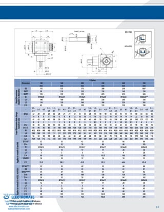
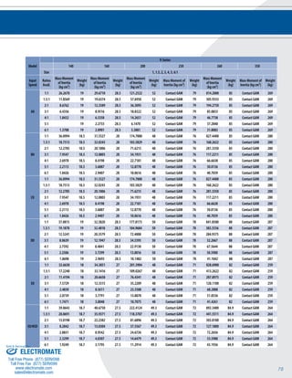
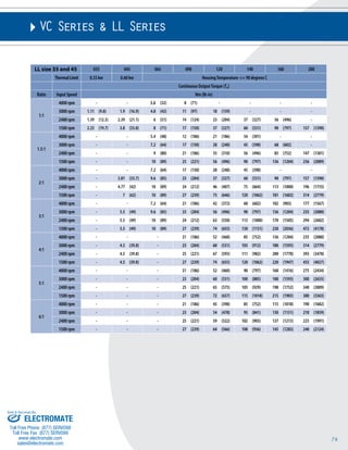
I.M.P.A.C.T.® Series - JPG-W
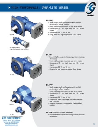
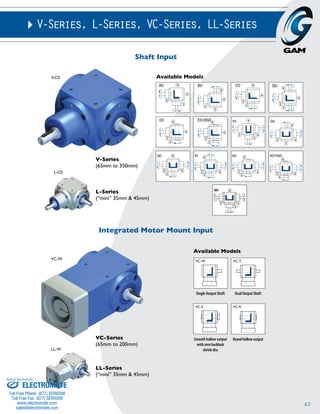
DL-PW
L8
Ø D6 H7
Recommended Output Coupling (if necessary)
metal bellows KLC-50 KLC-125 KM-270
elastomer EKC-80 EKC-110 EKM-300
Tolerances (mm)
Size k6 g6 H7
Over 18 +0.015 -0.007 +0.021
Thru 30 +0.002 -0.020 0
Over 30 +0.018 -0.009 +0.025
Thru 50 +0.002 -0.025 0
Over 50 +0.021 -0.010 +0.030
Thru 80 +0.002 -0.029 0
Over 80 +0.025 -0.012 +0.035
Thru 120 +0.003 -0.034 0
Over 120 +0.028 -0.014 +0.040
Thru 180 +0.003 -0.039 0
TYPE CODES FOR DYNA-LITE SERIES (DL-P)
Example: DL - PW - 075 - 005 H - [090 - 15A] - S111
Gearbox Series
DL = Dyna-Lite
Special Options
Assigned by GAM
Motor Mount Kit
Assigned by GAM
Gearbox Style
PW = shaft output
PH = hollow output
Gearbox Size
055, 075, 090
Ratio
5, 10, 15, 25, 50, 100
Options Available for This Product
G = Keyed output shaft
H = Smooth output shaft
Ø D1
L7
Ø D5
L6
Ø D3 g6
L4
L2
L5
L1
Ø D4
Ø D2 k6
DL-PH
Ø D6 H7
Ø D7
L11
L10
f2
DL - PW and DL - PH
55 75 90
mm (in) mm (in) mm (in)
D1 max (1 stage)* motor shaft diameter 16 (0.63) 20 (0.787) 35 (1.378)
D1 max (2 stage standard)* motor shaft diameter 14 (0.551) 19 (0.748) 19 (0.748)
D1 max (2 stage available)* motor shaft diameter 16 (0.63) 24 (0.945) 24 (0.945)
D2 k6 output shaft diameter 16 (0.63) 22 (0.866) 32 (1.26)
D3 g6 pilot diameter 60 (2.362) 70 (2.756) 90 (3.543)
D4 bolt circle 68 (2.677) 85 (3.346) 120 (4.724)
D5 mounting holes 5.5 (0.217) 6.6 (0.26) 9 (0.354)
D6 H7** hollow bore diameter 15 (0.591) 20 (0.787) 30 (1.181)
D7 shrink disc OD (included) 44 (1.732) 50 (1.969) 72 (2.835)
L1 1-stage***
gearbox length
172 (6.772) 206 (8.11) 249.5 (9.823)
L1 2-stage*** 236 (9.291) 304.5 (11.99) 336 (13.23)
L2 shaft length 48.0 (1.89) 56 (2.205) 80 (3.15)
L3 flange thickness 8.5 (0.335) 10 (0.394) 13 (0.512)
L4 usable shaft length 28 (1.102) 36 (1.417) 58 (2.283)
L5 pilot height 18 (0.709) 18 (0.709) 20 (0.787)
L6 flange size 66 (2.598) 76 (2.992) 101 (3.976)
L7 gear offset 9 (0.354) 14 (0.551) 18 (0.709)
L8 gearbox width 141.5 (5.571) 166 (6.535) 216 (8.504)
L10 shaft to centerline 95 (3.740) 110 (4.331) 148 (5.827)
L11 shrink disc to centerline estimated 70 (2.756) estimated 86 (3.386) estimated 108 (4.252)
F2 shaft thread per DIN332/1 M6 x 16 M8 x 19 M12x28
* for larger motor shaft diameters, please contact GAM **mating shaft should have h6 tolerance ***depending on motor, length may vary
Sold & Serviced By:
ELECTROMATE
Toll Free Phone (877) SERVO98
Toll Free Fax (877) SERV099
www.electromate.com
sales@electromate.com](https://image.slidesharecdn.com/gamrightanglegearreducerscatalog-141001201725-phpapp02/85/Gam-right-angle_gear_reducers_catalog-12-320.jpg)
![76
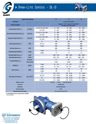
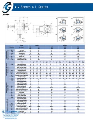
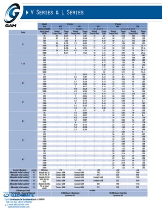
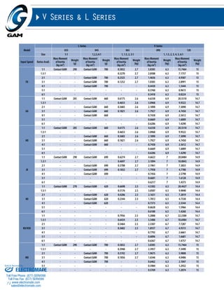
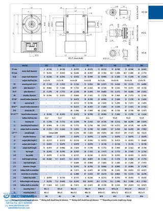
Performance: Spiral Bevel Series
Recommended Output Coupling
VC Series 035 045 065 090 120 140 160 200
bellows KG-5 or KM-4 KG-10 or KM-12 KM-12 or 20 KLC-25 or 50 KLC-50 or 125 KLC-125 or KM-170 KM-170,270 or 400 KM-270,400 or 550
elastomer EKC-5 EKM-8 or 15 EKC-5 or 25 EKC-35 or EKM-45 EKC-80 or 110 EKC-110 or EKM-200 EKM-200,300 or 400 EKM-300,500 or 700
TYPE CODES FOR VC SERIES / LL SERIES
Example: VC - W - 090 - 002 S - [115 - 2AA] - 1-S1-2500-E1-S111
Gearbox Series
VC - Spiral Bevel
Series (size65-200)
LL “mini” Spiral Bevel
Series (size 35 & 45)
Special Options
Assigned by GAM
Maximum Input Speed
Duty Cycle
S1 = continuous speed
S5 = cyclic
Motor Mount Kit
Assigned by GAM
Gearbox Style
K = Keyed hollow shaft
W = Single output shaft
T = Dual output shaft
S = Smooth hollow output
shaft with shrink disc
(not available in LL)
Gearbox Size
035, 045, 065, 090
120, 140, 160, 200
Sold & Serviced By:
Ratio
1, 1.5, 2, 3, 4, 5, 6
Mounting Configuration
Mounting Configuration
Breather Location
Backlash
S = Standard Backlash
R = Reduced Backlash
Shaft
Output
Hollow
Output
Breather Location
(if required)
TYPE CODES FOR V SERIES / L SERIES
Example: V - 090 - 1:1 - C0 - 750-9.1- E2/S1
Gearbox Series
V - Spiral Bevel
L - “Mini” Spiral
Bevel (size 035
and 045)
Duty Cycle
S1 Continuous
Speed
S5 Cyclic
Breather Location
If applicable
Mounting Side
9 = Standard
Tapped holes on housing
sides 1, 2, 4 and on
output flanges sides 5, 6
Gearbox Size
035, 045, 065, 090,
120, 140, 160, 200,
230, 260, 350
Ratio
1, 1.5, 2, 3, 4, 5, 6
Input Running Speed
0-3000 RPM
Gearbox Model
A0, B0, C0, D0, E0, E0/HSD, F0,
G0, H0, J0, K0, K0/HSD, M0
Mounting
Configuration
1,2,3,4,5,6
ELECTROMATE
Toll Free Phone (877) SERVO98
Toll Free Fax (877) SERV099
www.electromate.com
sales@electromate.com](https://image.slidesharecdn.com/gamrightanglegearreducerscatalog-141001201725-phpapp02/85/Gam-right-angle_gear_reducers_catalog-28-320.jpg)

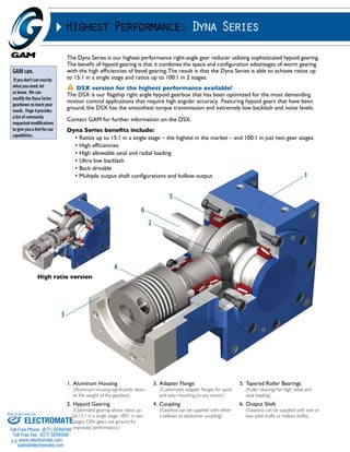
The document discusses GAM's Dyna Series right-angle gear reducers, which use hypoid gearing to achieve high ratios and efficiencies. The Dyna Series can achieve ratios up to 15:1 in a single stage and up to 100:1 in two stages. It is available in different configurations, including single output shaft, hollow bore output, and dual output shafts. The flagship DSX model features ground gears for improved performance. Key features include high ratios, efficiencies, loads, and low backlash.


![5G Explained! A High Level Overview [Introduction]](https://cdn.slidesharecdn.com/ss_thumbnails/5gexplainedahighleveloverview-260119165306-cc137a3e-thumbnail.jpg?width=640&height=640&fit=bounds)


