SlideShare a Scribd company logo
1 of 15
Download to read offline
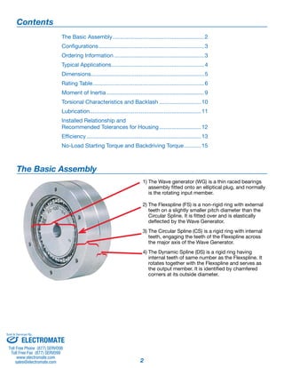
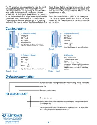
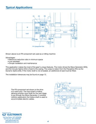
F R G e a r i n g 
Total Motion Control 
Harmonic Drive™gear P r e c i s i o n G e a r i n g a n d M o t i o n C o n t r o l
2 
The Basic Assembly 
{ {{ 
1) The Wave generator (WG) is a thin raced bearings 
assembly fitted onto an elliptical plug, and normally 
is the rotating input member. 
2) The Flexspline (FS) is a non-rigid ring with external 
teeth on a slightly smaller pitch diameter than the 
Circular Spline. It is fitted over and is elastically 
deflected by the Wave Generator. 
3) The Circular Spline (CS) is a rigid ring with internal 
teeth, engaging the teeth of the Flexspline across 
the major axis of the Wave Generator. 
4) The Dynamic Spline (DS) is a rigid ring having 
internal teeth of same number as the Flexspline. It 
rotates together with the Flexspline and serves as 
the output member. It is identified by chamfered 
corners at its outside diameter. 
Contents 
The Basic Assembly............................................................ 2 
Configurations..................................................................... 3 
Ordering Information........................................................... 3 
Typical Applications............................................................. 4 
Dimensions.......................................................................... 5 
Rating Table......................................................................... 6 
Moment of Inertia................................................................ 9 
Torsional Characteristics and Backlash............................ 10 
Lubrication......................................................................... 11 
Installed Relationship and 
Recommended Tolerances for Housing............................ 12 
Efficiency........................................................................... 13 
No-Load Starting Torque and Backdriving Torque............ 15 
Sold & Serviced By: 
ELECTROMATE 
Toll Free Phone (877) SERVO98 
Toll Free Fax (877) SERV099 
www.electromate.com 
sales@electromate.com
3 
The FR range has been developed to meet the trend 
towards flatter gear sets while retaining the many 
advantages of strain wave gearing. It consists of four 
main parts: Wave Generator, Flexspline, Dynamic 
Spline, and Circular Spline. When assembled, rotation 
of the Wave Generator as a high speed input member 
imparts a rotating elliptical shape to the Flexspline. 
This causes progressive engagement of its external 
teeth with the internal teeth of the Circular Spline. The 
fixed Circular Spline, having a larger number of teeth 
than the Flexspline causes the latter to precess at a 
rate determined by the ratio of tooth difference to the 
total number of teeth. 
With the same number of teeth as the Flexspline, 
The Dynamic Spline rotates with, and at the same 
speed as, the Flexspline and is the output member 
of the drive. 
Configurations 
1) Reduction Gearing 
WG Input 
CS Fixed 
DS Output 
Ratio as listed 
Input and output counter rotate. 
2) Reduction Gearing 
WG Input 
CS Output 
DS Fixed 
Ratio 
1 
R+1 
Input and output in same direction 
Output 
Input 
Output 
Input 
Output Input 
4) Differential 
WG Control Input 
CS Main-drive Input 
DS Main-drive Output 
Numerous differential functions can 
be obtained by combinations of 
speeds and rotations on the three 
shafts. 
3) Reduction Gearing 
WG Fixed 
CS Output 
DS Input 
Ratio 
R 
R+1 
Input and output in same direction. 
Output Input 
Ordering Information 
Pancake model having the double row bearing Wave Generator 
Size 20 
Reduction ratio 80:1 
Component set 
Suffix indicating that the set is optimized for servomechanism 
(See page 10). 
Suffix indicating that the set is specially modified or designed 
according to customer requirements. 
FR 20-80-2G-R-SP 
Sold & Serviced By: 
ELECTROMATE 
Toll Free Phone (877) SERVO98 
Toll Free Fax (877) SERV099 
www.electromate.com 
sales@electromate.com
Typical Applications 
Shown above is an FR component set used as a milling machine 
Advantages: 
4 
• Maximum reduction ratio in minimum space 
• Low backlash 
• Simple installation and maintenance 
This application makes the most of the gear's unique features. The motor drives the Wave Generator (WG), 
and the Circular Spline (CS) is fixed to the casing. The output is taken from the Flexspline (FS) via the 
Dynamic Spline (DS). If the motor shaft is not oil sealed, an additional oil seal must be fitted. 
The installation tolerances may be found on page 12. 
The FR component set shown is the drive 
of a robot joint. The input shaft is hollow, 
allowing another input shaft for the next stage 
to go through the Wave Generator. In another 
robotics application the hollow shaft is used to 
accommodate electric cables. 
Sold & Serviced By: 
ELECTROMATE 
Toll Free Phone (877) SERVO98 
Toll Free Fax (877) SERV099 
www.electromate.com 
sales@electromate.com
5 
Dimensions 
FR 14 20 25 32 40 50 65 80 100 
A (h6) 50 0 
-0.016 70 0 
-0.019 85 0 
-0.022 110 0 
-0.022 135 0 
-0.025 170 0 
-0.025 215 0 
-0.029 265 0 
-0.032 330 0 
-0.036 
B 8.5 12 14 18 21 26 35 41 50 
C 1 1 1 1 1 1 1 1 1 
D 18 25 29 37 43 53 71 83 101 
E — 17.3 20 25.9 31.5 39.1 50.5 62 77.2 
F — 3.85 4.5 5.55 5.75 6.95 10.25 10.5 11.9 
G 44 60 75 100 120 150 195 240 290 
H 6 6 6 6 6 6 6 8 8 
I M3 x 6 M3 x 6 M4 x 8 M5 x 10 M6 x 12 M8 x 16 M10 x 20 M10 x 20 M12 x 24 
(H7) 6 +0.012 9 +0.015 11 +0.018 14 +0.018 14 +0.018 19 +0.021 24 +0.021 28 +0.021 28 +0.021 
J 
0 
0 
0 
0 
0 
0 
0 
0 
0 
max. 8 11 11 17 20 26 26 32 32 
K (JS9) — 3±0.0125 4±0.0150 5±0.0150 5±0.0150 6±0.0150 8±0.0180 8±0.0180 8±0.0180 
L — 10.4 12.8 16.3 16.3 21.8 27.3 31.3 31.3 
M (C) 0,2 0.2 0.2 0.2 0.4 0.4 0.4 0.4 0.4 
N (C) 1 1 1.5 1.5 1.5 1.5 1.5 2 2 
U — — 22 28 32 38 44 52 58 
V — — 32 42 52 62 86 100 128 
W — — 4.8 6.1 7.6 9.8 12.6 16 19.7 
X — 42 1.6 1.9 2.5 3.2 4.4 5.1 6.3 
S 29 42 53 69 84 105 138 169 211 
Wt 
lb 0.4 1.1 1.8 3.7 6.8 13.2 27.3 48.9 93.5 
kgf 0.2 0.5 0.8 1.7 3.1 6.0 12.4 22.2 42.5 
* The axial location surfaces at D width must extend radially inward to at least to S for Flexspline containment. The surface hardness in the region where the Flexspline abuts is 
recommended to be RC29-34. ELECTROMATE 
Sold & Serviced By: 
Toll Free Phone (877) SERVO98 
Toll Free Fax (877) SERV099 
www.electromate.com 
sales@electromate.com
Rating Table 
FR Gear 
Ratio 
Rated 
Speed 
Rated Torque at 
2000rpm 
Repeated Peak 
Torque 
Max. Average 
Load Torque 
Max. Momentary 
Torque Max. Input Speed, rpm Limit for average Input 
Speed, rpm 
rpm N.m In.lb N.m In.lb N.m In.lb N.m In.lb Oil Lub. Grease Lub.** Oil Lub. Grease Lub.** 
14 
50 
2,000 
4.4 39 5.4 48 5.4 48 13.7 121 
6,000 3,600 4,000 2,500 
88 5.9 52 9.8 87 9.8 87 19.6 173* 
100 7.8 69 13.7 121 9.8 87 19.6 173* 
110 7.8 69 13.7 121 9.8 87 19.6 173* 
20 
50 
2,000 
25 221 34 301 34 301 69 611 
6,000 3,600 3,600 2,500 
80 34 301 41 363 41 363 72 637 
100 40 354 53 469 49 434 94 832 
128 40 354 67 593 49 434 102 903* 
160 40 354 77 681 49 434 86 761* 
25 
50 
2,000 
39 345 55 487 55 487 108 956 
5,000 3,600 3,000 2,500 
80 56 496 69 611 69 611 122 1,080 
100 67 593 91 805 91 805 160 1,416 
120 67 593 108 956 108 956 190 1,682 
160 67 593 135 1,195 108 956 172 1,522* 
200 67 593 147 1,301 108 956 172 1,522* 
32 
50 
2,000 
76 673 108 956 108 956 216 1,912 
4,500 3,600 2,500 2,300 
78 108 956 137 1,212 137 1,212 245 2,168 
100 137 1,212 176 1,558 176 1,558 323 2,859 
131 137 1,212 255 2,257 216 1,912 451 3,991 
157 137 1,212 294 2,602 216 1,912 500 4,425* 
200 137 1,212 314 2,779 216 1,912 372 3,292* 
260 137 1,212 314 2,779 216 1,912 372 3,292* 
40 
50 
2,000 
137 1,212 196 1,735 196 1,735 353 3,124 
4,000 3,300 2,000 2,000 
80 196 1,735 245 2,168 245 2,168 431 3,814 
100 255 2,257 314 2,779 314 2,779 549 4,859 
128 294 2,602 392 3,469 392 3,469 686 6,071 
160 294 2,602 461 4,080 451 3,991 813 7,195 
200 294 2,602 529 4,682 451 3,991 745 6,593* 
258 294 2,602 627 5,549 451 3,991 745 6,593* 
50 
80 
1,700 
363 3,213 440 3,894 441 3,903 784 6,938 
3,500 3,000 1,700 1,700 
100 470 4,160 578 5,115 578 5,115 1,019 9,018 
120 559 4,947 696 6,160 696 6,160 1,225 10,841 
160 559 4,947 833 7,372 833 7,372 1,470 13,010 
200 559 4,947 960 8,496 843 7,461 1,411 12,487* 
242 559 4,947 1176 10,408 843 7,461 1,411 12,487* 
65 
78 
1,400 
745 6,593 921 8,151 921 8,151 1,617 14,311 
3,000 2,200 1,400 1,400 
104 1,070 9,470 1,340 11,859 1,340 11,859 2,360 20,886 
132 1,070 9,470 1,650 14,603 1,570 13,895 2,890 25,577 
158 1,070 9,470 1,970 17,435 1,570 13,895 3,450 30,533* 
208 1,070 9,470 2,180 19,293 1,570 13,895 2,590 22,922* 
260 1,070 9,470 2,200 19,470 1,570 13,895 2,590 22,922* 
80 
80 
1,200 
1,320 11,682 1,640 14,514 1,640 14,514 2,870 25,400 
2,500 2,000 1,200 1,200 
96 1,660 14,691 2,050 18,143 2,050 18,143 3,580 31,772 
128 2,300 20,355 2,820 24,957 2,830 25,046 4,960 43,896 
160 2,360 20,798 3,380 29,913 3,130 27,701 5,940 52,569 
194 2,350 20,798 4,300 38,055 3,130 27,701 6,900 61,065* 
258 2,350 20,798 4,350 38,498 3,130 27,701 5,170 45,755 
320 2,350 20,798 4,350 38,498 3,130 27,701 5,170 45,755* 
100 
80 
1,000 
2,350 20,621 2,870 25,400 2,870 25,400 5,040 44,604 
2,000 1,700 1,000 1,000 
100 2,330 28,320 3,940 34,869 3,940 34,869 6,920 61,242 
120 3,200 34,427 4,780 42,303 4,780 42,303 8,400 74,340 
160 4,470 39,560 6,230 55,136 5,720 50,622 10,950 96,908 
200 4,470 39,560 7,090 62,747 5,720 50,622 12,440 110,094 
242 4,470 39,560 7,960 70,446 5,720 50,622 9,410 83,279* 
320 4,470 39,560 7,960 70,446 5,720 50,622 9,410 83,279* 
*Torque value limited by “Ratcheting”, see page 8. **For operating conditions see grease lubrication, page 11.
7 
How To Use The Rating Table 
Because of their simple, convenient construction 
and positional and rotational accuracy, Harmonic 
Drive™ component sets are used in large numbers 
in servo-controlled drives where the load and driving 
speed are seldom constant. With such applications in 
mind, the rating table presents four important torque 
capacity limits: 
• Rated Torque at rated speed 
• Allowable limit for Average Torque 
• Allowable limit for repeated Peak Torque 
• Allowable limit for Momentary Peak Torque 
Rated Toque at Rated Input Speed 
This is the maximum allowable output torque that 
can be developed continuously at the rated input 
speed shown in the first column. When a Harmonic 
Drive™ FR product is to be operated at speeds other 
than the rated torque, the actual torque load at each 
speed needs to be converted to an Equivalent Torque 
(Teq) using formulas 1, 2, and 3 on page 9. 
Allowable Limit for Average torque 
When a Harmonic Drive™ FR product is used under 
a variable load, Average Torque may be calculated by 
formula 1 on page 9. Thus calculated Average Torque 
should not exceed this limit. Ignoring this limit will 
result in excessive heat generation, tooth wear, and 
deterioration of lubricant. 
Allowable Limit for Repeated Peak Torque 
This is the allowable output torque that can be 
developed when starting and stopping operation. Peak 
torque developed at starting and stopping can be 
estimated if the moment of inertia of motor and load, 
and accelerating (or decelerating) time are known. 
Allowable Limit for Momentary Peak torque 
Aside form the peak torque developed at starts and 
stops, FR unit transmission may be subjected to yet 
another type of peak torque, an example of which 
is the shock load generated by an emergency stop 
of the servo system. Another example is the shock 
load generated when the driven element, such as 
a robot hand, accidentally hits a hard object. The 
Rating Table gives the limit for such Momentary 
Peak Torque. Momentary Peak Torque must be 
restricted not only in its value but also in its 
frequency of occurrence. This is further explained 
in the next chapter titled “Factors Affecting Torque 
Capabilities.” 
The variation of load and speed in typical operating cycles are schematically illustrated in the diagrams below. 
Sold & Serviced By: 
ELECTROMATE 
Toll Free Phone (877) SERVO98 
Toll Free Fax (877) SERV099 
www.electromate.com 
sales@electromate.com
Factors Affecting Torque Capabilities 
8 
The torque capabilities quoted in the Rating Table 
are determined by considering three factors: the 
strength of the Flexspline, the unit’s ability to resist a 
phenomenon called ratcheting, and the operating life 
of the Wave Generator bearing. 
Flexspline Strength 
The Flexspline, the non-rigid member, is subjected 
to repeated deflections, and its strength limits the 
rating of the entire unit. The values given for Rated 
Torque at Rated Speed, Limits for Average Torque, 
and repeated Peak Torque are for the infinite fatigue 
life of the Flexspline. The Limit For Momentary Peak 
torque, however, exceeds the infinite fatigue limit of the 
Flexspline, and the load at this level must be restricted 
to 1x10⁴ flex-cycles. Operating conditions exceeding 
the limit will lead to failure of the Flexspline. 
The allowable frequency of occurrence (N) of 
Momentary Peak Torque may be calculated by: 
where n is the input speed in rpm and t is the 
duration of Momentary Peak Torque in seconds. 
Note that there are two flex-cycles for each input 
revolution. For example, if Momentary peak torque is 
expected to occur at a 2,00 rpm input speed and to 
last for 0.15 seconds, then: 
Ratcheting 
Another torque limit for under dynamic load is set 
by a momentary load releasing phenomenon called 
ratcheting. This is slippage of the meshing of the 
Circular Spline and Flexspline teeth as the result of 
deformation of drive members under excessive load. 
In the Rating Table, values marked with asterisk(*) 
are the torque limits related to ratcheting. 
Ratcheting usually does not lead to immediate drive 
failure, but may result in “dedoidal”, an improper 
tooth mesh that may cause undesirable vibration 
or eventual failure of the Flexspline. The ratchet 
point will decrease with each subsequent incident, 
and should not be intentionally utilized for machine 
overload protection purposes. 
Operator Life of the Wave Generator Bearing 
The life expectancies of Harmonic Drive™ 
component sets are based on the median life of the 
Wave Generator bearing. Rated Torque at Rated 
Speeds are based on a median bearing life (L50) 
of approximately 15,000 hours. This means that 
operated at the constant rated speed and rated 
torque, 50 percent of a group of bearings would fail 
before these service hours. 
Life expectancy of a unit operated at speed n 
and torque T conditions may be estimated by the 
relationship given below: 
Operating Speed 
The Rating Table gives two limits, Maximum Input 
Speed and Limit for Average Input Speed, for both 
oil-lubricated and grease-lubricated units. Units 
may be operated continuously up to the maximum 
input speed limits, provided that the average speed 
during the operation, as calculated by formula 2, on 
pages 11 and 12, does not exceed the limit for the 
average input speed. 
For continuous operation of grease-lubricated units 
at these speed limits, it is recommended that grease 
specially developed for Harmonic Drive™ gears be 
used. For a list of recommended available lubricants, 
see page 10 and 11. 
How To Select A Unit From The Rating Table 
In actual applications, operating conditions are 
seldom constant. Torque and speed vary, and 
peak torque develops during acceleration and 
deceleration. The first step is to convert these 
variable torques and speeds to a constant average 
torque and speed. 
Step 1: Average Torque and Speed 
Consider a hypothetical operating cycle such as 
shown in the diagram on the following page 
T1 is the Peak torque developed during the 
acceleration t1, T2 is the Operational torque at 
constant speed n2 that lasts for a period of t2, and 
T3 is the Peak Torque developed during acceleration 
t3. n1 and n3 represent the Average Speed during 
acceleration and deceleration, which in this case are 
Sold & Serviced By: 
ELECTROMATE 
Toll Free Phone (877) SERVO98 
Toll Free Fax (877) SERV099 
www.electromate.com 
sales@electromate.com
9 
The Average Torque Tav for this cycle is calculated: 
The Average Speed nav for this cycle is 
Step 2 
The second step is to calculate as below an 
Equivalent Torque Teq that would give a median 
bearing life of 15,000 hours. 
Step 3 
The third step is to estimate the level of Momentary 
Peak Torque and the frequency of its occurrence. 
Estimated Momentary Peak Torque must be less than 
the allowable limit given in the Rating Table, and the 
frequency of its occurrence must not exceed 1x10⁴ 
flex-cycles. 
Step 4 
The fourth step is to check these operating 
conditions against the values and limits given in the 
Rating Table for a unit under consideration. If any of 
the operating conditions exceed the limits, either the 
operating condition must be relaxed or another unit 
must be selected. 
Example 
A drive unit FR 40 ratio 100:1 is being considered for 
these operating torques and speeds: 
Torque 
• Peak torque during acceleration T1.......2500 lb-in 
• Operating torque T2...............................1740 lb-in 
• Peak torque during deceleration T3.......2200 lb-in 
Time 
• Accelerating time t1........................... 0.2 seconds 
• Operating time t2............................... 2.0 seconds 
• Decelerating time t3........................... 0.3 seconds 
Speed 
• Operating speed n2............................... 2200 rpm 
• Average speed during acceleration and 
deceleration n1 and n3........................... 1100 rpm 
Step 1 
=1826 lb-in 
nav= 1100x0.2+2200x2+1100x0.3 =1980 rpm 
0.2+2+0.3 
Step 2 
Step 3 
It is estimated that approximately 4,500 lb-in of peak 
torque will develop momentarily at an emergency 
stop, which is estimated to take place at 2,200 rpm 
and last for 0.15 seconds. Allowable frequency of 
such Momentary Peak Torque is: 
Step 4: Conclusion 
Entering the Rating Table at the line corresponding to 
FR 40-100 we find that Teq, Tav, Repeated Peak Torque 
and Momentary Peak Torque values, and speed 
conditions of this application are within the allowable 
limits: 
Estimated Operating 
Conditions 
Rating and 
Limits 
Equivalent Torque Teq 1,820 lb-in 2,220 lb-in 
Average Torque, Tav 1,826 lb-in 2,780 lb-in 
Repeated Peak Torque 2,500 and 2,200 lb-in 2,770 lb-in 
Momentary Peak Torque 4,500 lb-in 4,860 lb-in 
Average Speed, nav 1,980 rpm 2,000 rpm 
Therefore, this unit is considered adequate for 
this application. It can be lubricated either with 
oil or Harmonic Grease SK-1. The occurrence of 
emergency stops must be less than 900 times during 
the expected service life of this unit. 
Sold & Serviced By: 
ELECTROMATE 
Toll Free Phone (877) SERVO98 
Toll Free Fax (877) SERV099 
www.electromate.com 
sales@electromate.com
10 
Moment of Inertia 
Inertia values at the high-speed shaft for FR 
component sets are given in table below. 
Units with reduced input inertia may be supplied 
on a custom basis. Since the reduction of inertia 
is achieved by modifying the Wave generator 
and may affect the unit’s torque capacity, each 
application requiring reduced inertia needs to be 
evaluated individually. 
FR 14 20 25 32 40 50 65 80 100 
Moment of 
Inertia J 
kg-cm2 0.06 0.32 0.70 2.6 6.8 21 76 213 635 
lb-in2 0.02 0.11 0.24 0.89 2.3 7.1 26 73 217 
Torsional Characteristics and Backlash 
The torsional characteristics of the drive are an 
important consideration in a servo-drive system. 
When torque is applied to the output of the gear unit 
with the input rotationally locked, the torque-torsion 
relationship measured at the output typically follows 
the loop O-A-B-A’-B’-A illustrated. 
Three major characteristics of interest in a servo 
driver are: 
1) The gear exhibits soft wind-up characteristics in 
the low torque region. The spring rates for three 
regions of the torque-torsion curve are given on 
pages 9 and 10. 
2) The backlash in an assembled component set is 
defined as pure play existing between the input 
and output. Because of double row teeth mesh, 
FR component set exhibits backlash somewhat 
larger than CSF component sets. Backlash of 
Series R (for robotics application) is optimized 
below 1.5 minutes of arc for all sizes. Backlash 
ofnon-optimized units are quoted below. Values 
are measured at output with input looked. 
Backlash in assembled FR 
FR 14 20 25 32 40 50 65 80 100 
Optimized, less than 1.5 1.5 1.5 1.5 1.5 1.5 1.5 1.5 1.5 
Spring Rate 
For servo-drive applications, the torsional stiffness of 
the FR component set may be evaluated by dividing 
the torque-torsion curve in three major regions: a 
small torque region O-T1, a middle torque region 
T1-T2, and a linear region T2-T3. Spring rates of these 
regions vs. size standard units are tabulated. The 
values quoted are the average of many tests of actual 
units. The spring rate of an individual unit may vary 
within approximately ±30% of the average. 
Torque-Torsion Curve 
K1: Spring rate for torque region O-T1 
K2: Spring rate for torque region T1-T2 
K3: Spring rate for torque region over T2 
min. of arc 
Sold & Serviced By: 
ELECTROMATE 
Toll Free Phone (877) SERVO98 
Toll Free Fax (877) SERV099 
www.electromate.com 
sales@electromate.com
11 
Spring Rate FR Component Sets Series R 
FR 
T1 K1x104/rad T2 K2x104/rad K3x104/rad 
Nm lb-in Nm lb-in Nm lb-in Nm lb-in Nm lb-in 
14 1.0 8.9 0.26 2.3 5.0 44 0.64 5.7 1.0 8.9 
20 2.0 17.4 0.81 7.2 23 200 2.8 25 3.0 27 
25 5.0 43 1.6 14 37 330 3.7 33 5.4 48 
32 9.0 78 2.8 25 78 690 8.4 74 12 106 
40 18 156 6.1 54 156 1380 18 159 24 212 
50 34 304 12 106 294 2600 34 300 48 425 
65 78 694 26 230 549 4860 64 566 84 743 
80 147 1300 51 451 1078 9550 130 1150 165 1460 
Lubrication 
As with CSF component sets, oil lubrication is 
preferred. Although FR sets may be used in any 
attitude, it is essential that the wave generator 
bearing and gear teeth be properly lubricated. 
Minimum required oil amounts are tabulated below, 
but the actual amount will depend on the size of the 
housing. 
In the case of horizontal shaft installation, the 
appropriate oil level below the gear set center 
line must be maintained as tabulated. For vertical 
mounting, the recommended level is the center line of 
the Upper Wave generator bearing balls. 
Oil Level and Minimum Oil Quantity 
Oil Temperature 
In normal use, the oil temperature must not exceed 
90˚C, as oil loses its lubricating capability quickly 
above this limit. 
Oil Change 
The first change should be performed after 100 hours 
of operation. The need to perform subsequent oil 
changes will depend on operating conditions, but 
should take place at intervals of approximately 1,000 
running hours. 
Calculation Example 
This formula is used to find the total wind-up (θ) at 
the output of an FR 25 ratio 100:1, when a torque 
load of 600 lb-in is applied. 
Grease Lubrication 
FR component sets may be operated with grease 
lubrication at rated torque but at reduced duty cycle. 
Imperial Molub Alloy No. 2 is recommended. 
Grease lubrication may be used in applications where 
the duty cycle is less than 10 percent time-on and 
the length of time-on does not exceed 10 minutes of 
continuous operation. The maximum input speeds 
allowable for units lubricated by Molub Alloy No. 2 
are given below: 
Harmonic Grease HC-1 
As a result of an extensive search for a grease that 
will render improved performance in Harmonic 
Drive™ gears, a new grease, named Harmonic 
Grease HC-1, has been developed. With Harmonic 
Grease HC-1, units may be operated continuously. 
An important consideration in grease lubrication is 
ensuring that as much grease as possible is retained 
where lubrication is needed. To achieve this, it is 
recommended that the axial location surfaces at D 
width extend radially inward to the dimension shown. 
However, such an extension is not recommended for 
oil lubrication. 
FR 14 20 25 32 40 50 65 80 100 
A mm 7 12 15 31 38 44 62 75 94 
FR 14 20 25 32 40 50 65 80 100 
S 24.5 38 48 63 76 95 126 152 190 
mm 
FR 14 20 25 32 40 50 65 80 100 
S 24.5 38 48 63 76 95 126 152 190
12 
Grease Changes 
When operating the FR at rated torque, change 
grease after about 1,00 running hours. Light duty 
operation may permit longer service intervals. To 
change grease, Completely disassemble and clean 
units before re-greasing. Apply grease generously 
inside the Flexspline, the Wave generator bearing, 
and teeth of both the Circular and Dynamic Splines 
and the Flexspline. 
The approximate amount of grease needed for 
each Harmonic Drive™ FR Component Set is 
tabulated below: 
FR 14 20 25 32 40 50 65 80 100 
Grease 
Weight 
gr. 8 18 30 60 100 150 320 570 1150 
oz. 0,3 0.6 1 2 3.5 5.5 11 20 40 
Installed Relationship and Recommended Tolerances for Housing 
The Dynamic Spline is distinguished by its chamfered 
outer edge. FR component sets may be operated in 
any attitude with suitable bearing support of the input 
and output shaft, and a means of fixing the Circular 
Spline against rotation. Recommended installed 
relationships for the Series R units, (recommended 
for robotics application) are shown below: 
FR a b c d e f g h 
14 0.013 0.015 0.016 0.013 0.015 0.016 0.011 0.007 
20 0.017 0.016 0.020 0.017 0.016 0.020 0.013 0.010 
25 0.024 0.016 0.029 0.024 0.016 0.029 0.016 0.012 
32 0.026 0.017 0.031 0.026 0.017 0.031 0.016 0.012 
40 0.026 0.019 0.031 0.026 0.019 0.031 0.017 0.012 
50 0.028 0.024 0.034 0.028 0.024 0.034 0.021 0.015 
65 0.034 0.027 0.041 0.034 0.027 0.041 0.025 0.015 
80 0.043 0.033 0.052 0.043 0.033 0.052 0.030 0.015 
100 0.057 0.038 0.068 0.057 0.038 0.068 0.035 0.015 
Sold & Serviced By: 
ELECTROMATE 
Toll Free Phone (877) SERVO98 
Toll Free Fax (877) SERV099 
www.electromate.com 
sales@electromate.com
13 
Efficiency 
Efficiency varies depending on input speed, ratio, load level, temperature, and type of lubrication. The effect 
of these factors are illustrated in the curves shown. 
Efficiency vs. Speed, Temperature, Reduction Ratio, and oil Lubrication 
Chart 1 Chart 2 
Chart 3 Chart 4 
Sold & Serviced By: 
ELECTROMATE 
Toll Free Phone (877) SERVO98 
Toll Free Fax (877) SERV099 
www.electromate.com 
sales@electromate.com
14 
Efficiency (cont.) 
Chart 5 Chart 6 
Chart 7 Chart 8 
Sold & Serviced By: 
ELECTROMATE 
Toll Free Phone (877) SERVO98 
Toll Free Fax (877) SERV099 
www.electromate.com 
sales@electromate.com
15 
Efficiency vs. Load 
Efficiency of the gears vary depending on output 
torque. The efficiency curves given on the preceding 
pages are for units operating at an output torque 
rated for 2,00 rpm. Efficiency of a unit operating at a 
load below the rated torque may be estimated using 
a compensation curve and formula shown below. 
Ex. Efficiency of an FR 40-160-2GR operating at an input speed of 1,00 rpm, output torque of 1,560 lb-in, and 
at 40˚C may be estimated as follows: 
Torque ratio= 1,560 =0.6 
2,600 
Ke=0.87 
Efficiency (at 1,560 lb-in) = 58 x 0.87 = 50% 
No-Load Starting Torque and Backdriving Torque 
FR 14 20 25 32 40 50 65 80 100 
Starting 
Torque 
Ncm 0.7~4 0.7~6 0.7~20 1~30 3~50 4~100 7~200 28~280 98~680 
oz-in 1~5 1~8 1~28 1.4~42 4.2~70 5~140 10~280 40~400 140~970 
Backdriving 
Torque 
Nm 0.7~10 1~19 3~48 4~80 7~190 15~340 30~480 48~790 290~2500 
lb-in 6~90 9~170 26~430 35~700 60~1700 130~3000 260~4300 430~7000 2600~22000 
Values quoted are based on actual tests with the component sets assembled in their housings, and inclusive 
of friction resistance of oils seals, and churning of oil. 
Sold & Serviced By: 
ELECTROMATE 
Toll Free Phone (877) SERVO98 
Toll Free Fax (877) SERV099 
www.electromate.com 
sales@electromate.com

More Related Content

What's hot

2002 Polaris 600 XC SP SNOWMOBILE Service Repair Manual
2002 Polaris 600 XC SP SNOWMOBILE Service Repair Manual2002 Polaris 600 XC SP SNOWMOBILE Service Repair Manual
2002 Polaris 600 XC SP SNOWMOBILE Service Repair Manualjkmdmd yksejkdmm
 
Harmonic shd 2uh_lw_catalog
Harmonic shd 2uh_lw_catalogHarmonic shd 2uh_lw_catalog
Harmonic shd 2uh_lw_catalogElectromate
 
Hmc l4 kb9 sm 20090824 (1)
Hmc l4 kb9 sm 20090824 (1)Hmc l4 kb9 sm 20090824 (1)
Hmc l4 kb9 sm 20090824 (1)Artem Malitskiy
 
1987 PONTIAC FIREBIRD Service Repair Manual
1987 PONTIAC FIREBIRD Service Repair Manual1987 PONTIAC FIREBIRD Service Repair Manual
1987 PONTIAC FIREBIRD Service Repair Manualjhdnjdn sekjmd
 
Gam ekm_Spec Sheet
Gam ekm_Spec SheetGam ekm_Spec Sheet
Gam ekm_Spec SheetElectromate
 
Torque systems mdm-5000_product_guide
Torque systems mdm-5000_product_guideTorque systems mdm-5000_product_guide
Torque systems mdm-5000_product_guideElectromate
 
Inertia dynamics shaftmtdbrake310_specsheet
Inertia dynamics shaftmtdbrake310_specsheetInertia dynamics shaftmtdbrake310_specsheet
Inertia dynamics shaftmtdbrake310_specsheetElectromate
 
Gam skg_Spec Sheet
Gam skg_Spec SheetGam skg_Spec Sheet
Gam skg_Spec SheetElectromate
 
Cách chọn chế độ lắp
Cách chọn chế độ lắpCách chọn chế độ lắp
Cách chọn chế độ lắpdinhductrong9999
 
Lintech ball screw_option_specsheet
Lintech ball screw_option_specsheetLintech ball screw_option_specsheet
Lintech ball screw_option_specsheetElectromate
 
Shimpo er series
Shimpo er seriesShimpo er series
Shimpo er seriesElectromate
 
Gam linear mount_products_catalog
Gam linear mount_products_catalogGam linear mount_products_catalog
Gam linear mount_products_catalogElectromate
 
CS Unitec Nut Runners: 6 1014 0075
CS Unitec Nut Runners: 6 1014 0075CS Unitec Nut Runners: 6 1014 0075
CS Unitec Nut Runners: 6 1014 0075CS Unitec
 
CS Unitec Nut Runners: 6 1014 0010
CS Unitec Nut Runners: 6 1014 0010CS Unitec Nut Runners: 6 1014 0010
CS Unitec Nut Runners: 6 1014 0010CS Unitec
 
Hoyer IE3 Electric Motors
Hoyer IE3 Electric MotorsHoyer IE3 Electric Motors
Hoyer IE3 Electric MotorsArve
 
CS Unitec Nut Runners: 6 1014 0099
CS Unitec Nut Runners: 6 1014 0099CS Unitec Nut Runners: 6 1014 0099
CS Unitec Nut Runners: 6 1014 0099CS Unitec
 
Shimpo able vral_catalog
Shimpo able vral_catalogShimpo able vral_catalog
Shimpo able vral_catalogElectromate
 

What's hot (18)

2002 Polaris 600 XC SP SNOWMOBILE Service Repair Manual
2002 Polaris 600 XC SP SNOWMOBILE Service Repair Manual2002 Polaris 600 XC SP SNOWMOBILE Service Repair Manual
2002 Polaris 600 XC SP SNOWMOBILE Service Repair Manual
 
Harmonic shd 2uh_lw_catalog
Harmonic shd 2uh_lw_catalogHarmonic shd 2uh_lw_catalog
Harmonic shd 2uh_lw_catalog
 
Hmc l4 kb9 sm 20090824 (1)
Hmc l4 kb9 sm 20090824 (1)Hmc l4 kb9 sm 20090824 (1)
Hmc l4 kb9 sm 20090824 (1)
 
1987 PONTIAC FIREBIRD Service Repair Manual
1987 PONTIAC FIREBIRD Service Repair Manual1987 PONTIAC FIREBIRD Service Repair Manual
1987 PONTIAC FIREBIRD Service Repair Manual
 
Gam ekm_Spec Sheet
Gam ekm_Spec SheetGam ekm_Spec Sheet
Gam ekm_Spec Sheet
 
E1267
E1267E1267
E1267
 
Torque systems mdm-5000_product_guide
Torque systems mdm-5000_product_guideTorque systems mdm-5000_product_guide
Torque systems mdm-5000_product_guide
 
Inertia dynamics shaftmtdbrake310_specsheet
Inertia dynamics shaftmtdbrake310_specsheetInertia dynamics shaftmtdbrake310_specsheet
Inertia dynamics shaftmtdbrake310_specsheet
 
Gam skg_Spec Sheet
Gam skg_Spec SheetGam skg_Spec Sheet
Gam skg_Spec Sheet
 
Cách chọn chế độ lắp
Cách chọn chế độ lắpCách chọn chế độ lắp
Cách chọn chế độ lắp
 
Lintech ball screw_option_specsheet
Lintech ball screw_option_specsheetLintech ball screw_option_specsheet
Lintech ball screw_option_specsheet
 
Shimpo er series
Shimpo er seriesShimpo er series
Shimpo er series
 
Gam linear mount_products_catalog
Gam linear mount_products_catalogGam linear mount_products_catalog
Gam linear mount_products_catalog
 
CS Unitec Nut Runners: 6 1014 0075
CS Unitec Nut Runners: 6 1014 0075CS Unitec Nut Runners: 6 1014 0075
CS Unitec Nut Runners: 6 1014 0075
 
CS Unitec Nut Runners: 6 1014 0010
CS Unitec Nut Runners: 6 1014 0010CS Unitec Nut Runners: 6 1014 0010
CS Unitec Nut Runners: 6 1014 0010
 
Hoyer IE3 Electric Motors
Hoyer IE3 Electric MotorsHoyer IE3 Electric Motors
Hoyer IE3 Electric Motors
 
CS Unitec Nut Runners: 6 1014 0099
CS Unitec Nut Runners: 6 1014 0099CS Unitec Nut Runners: 6 1014 0099
CS Unitec Nut Runners: 6 1014 0099
 
Shimpo able vral_catalog
Shimpo able vral_catalogShimpo able vral_catalog
Shimpo able vral_catalog
 

Viewers also liked

Harmonic hpn gearhead_catalog
Harmonic hpn gearhead_catalogHarmonic hpn gearhead_catalog
Harmonic hpn gearhead_catalogElectromate
 
Harmonic hdi infinit-indexer-catalog
Harmonic hdi infinit-indexer-catalogHarmonic hdi infinit-indexer-catalog
Harmonic hdi infinit-indexer-catalogElectromate
 
THE STYLEMATE 01/2016 GOING GREEN
THE STYLEMATE 01/2016 GOING GREEN THE STYLEMATE 01/2016 GOING GREEN
THE STYLEMATE 01/2016 GOING GREEN THE Stylemate
 
Harmonic hpf series_specsheet
Harmonic hpf series_specsheetHarmonic hpf series_specsheet
Harmonic hpf series_specsheetElectromate
 
Best Use of Emerging Platform by Airline - SimpliFlying Awards 2014
Best Use of Emerging Platform by Airline - SimpliFlying Awards 2014Best Use of Emerging Platform by Airline - SimpliFlying Awards 2014
Best Use of Emerging Platform by Airline - SimpliFlying Awards 2014SimpliFlying
 
Most Creative Campaign by Airline - SimpliFlying Awards 2014
Most Creative Campaign by Airline - SimpliFlying Awards 2014Most Creative Campaign by Airline - SimpliFlying Awards 2014
Most Creative Campaign by Airline - SimpliFlying Awards 2014SimpliFlying
 
Top 50 case-studies of airlines and airports excelling in social media
Top 50 case-studies of airlines and airports excelling in social mediaTop 50 case-studies of airlines and airports excelling in social media
Top 50 case-studies of airlines and airports excelling in social mediaSimpliFlying
 
88 flight attendant interview questions and answers
88 flight attendant interview questions and answers88 flight attendant interview questions and answers
88 flight attendant interview questions and answersFlightAttendant247
 
Southwest Airlines : Case Study
Southwest Airlines : Case StudySouthwest Airlines : Case Study
Southwest Airlines : Case StudySarang Bhutada
 

Viewers also liked (9)

Harmonic hpn gearhead_catalog
Harmonic hpn gearhead_catalogHarmonic hpn gearhead_catalog
Harmonic hpn gearhead_catalog
 
Harmonic hdi infinit-indexer-catalog
Harmonic hdi infinit-indexer-catalogHarmonic hdi infinit-indexer-catalog
Harmonic hdi infinit-indexer-catalog
 
THE STYLEMATE 01/2016 GOING GREEN
THE STYLEMATE 01/2016 GOING GREEN THE STYLEMATE 01/2016 GOING GREEN
THE STYLEMATE 01/2016 GOING GREEN
 
Harmonic hpf series_specsheet
Harmonic hpf series_specsheetHarmonic hpf series_specsheet
Harmonic hpf series_specsheet
 
Best Use of Emerging Platform by Airline - SimpliFlying Awards 2014
Best Use of Emerging Platform by Airline - SimpliFlying Awards 2014Best Use of Emerging Platform by Airline - SimpliFlying Awards 2014
Best Use of Emerging Platform by Airline - SimpliFlying Awards 2014
 
Most Creative Campaign by Airline - SimpliFlying Awards 2014
Most Creative Campaign by Airline - SimpliFlying Awards 2014Most Creative Campaign by Airline - SimpliFlying Awards 2014
Most Creative Campaign by Airline - SimpliFlying Awards 2014
 
Top 50 case-studies of airlines and airports excelling in social media
Top 50 case-studies of airlines and airports excelling in social mediaTop 50 case-studies of airlines and airports excelling in social media
Top 50 case-studies of airlines and airports excelling in social media
 
88 flight attendant interview questions and answers
88 flight attendant interview questions and answers88 flight attendant interview questions and answers
88 flight attendant interview questions and answers
 
Southwest Airlines : Case Study
Southwest Airlines : Case StudySouthwest Airlines : Case Study
Southwest Airlines : Case Study
 

Similar to Harmonic fr specsheet

Harmonic fb specshseet
Harmonic fb specshseetHarmonic fb specshseet
Harmonic fb specshseetElectromate
 
Harmonic hpgp specsheet
Harmonic hpgp specsheetHarmonic hpgp specsheet
Harmonic hpgp specsheetElectromate
 
Harmonic csf csg_catalog
Harmonic csf csg_catalogHarmonic csf csg_catalog
Harmonic csf csg_catalogElectromate
 
Harmonic drive csd specsheet
Harmonic drive csd specsheetHarmonic drive csd specsheet
Harmonic drive csd specsheetElectromate
 
Harmonic csg lw_spechseet
Harmonic csg lw_spechseetHarmonic csg lw_spechseet
Harmonic csg lw_spechseetElectromate
 
Harmonic drive hdt t cup_specsheet
Harmonic drive hdt t cup_specsheetHarmonic drive hdt t cup_specsheet
Harmonic drive hdt t cup_specsheetElectromate
 
Harmonic csf lw_specsheet
Harmonic csf lw_specsheetHarmonic csf lw_specsheet
Harmonic csf lw_specsheetElectromate
 
Shimpo circulute 3000_pulley_specsheet
Shimpo circulute 3000_pulley_specsheetShimpo circulute 3000_pulley_specsheet
Shimpo circulute 3000_pulley_specsheetElectromate
 
Inertia dynamics shaftmtdbrake307_specsheet
Inertia dynamics shaftmtdbrake307_specsheetInertia dynamics shaftmtdbrake307_specsheet
Inertia dynamics shaftmtdbrake307_specsheetElectromate
 
Inertia dynamics cb_couplings310_specsheet
Inertia dynamics cb_couplings310_specsheetInertia dynamics cb_couplings310_specsheet
Inertia dynamics cb_couplings310_specsheetElectromate
 
Kollmorgen b with_servo_star_s_and_cd_tb_catalog
Kollmorgen b with_servo_star_s_and_cd_tb_catalogKollmorgen b with_servo_star_s_and_cd_tb_catalog
Kollmorgen b with_servo_star_s_and_cd_tb_catalogElectromate
 
Inertia dynamics clutch310_specsheet
Inertia dynamics clutch310_specsheetInertia dynamics clutch310_specsheet
Inertia dynamics clutch310_specsheetElectromate
 
Iai isdbcr ispdbcr_esd_specsheet
Iai isdbcr ispdbcr_esd_specsheetIai isdbcr ispdbcr_esd_specsheet
Iai isdbcr ispdbcr_esd_specsheetElectromate
 
Inertia dynamics cb_couplings308_specsheet
Inertia dynamics cb_couplings308_specsheetInertia dynamics cb_couplings308_specsheet
Inertia dynamics cb_couplings308_specsheetElectromate
 
Inertia dynamics flangemtbk310p_specsheet
Inertia dynamics flangemtbk310p_specsheetInertia dynamics flangemtbk310p_specsheet
Inertia dynamics flangemtbk310p_specsheetElectromate
 
Inertia dynamics clutchcplng308p_specsheet
Inertia dynamics clutchcplng308p_specsheetInertia dynamics clutchcplng308p_specsheet
Inertia dynamics clutchcplng308p_specsheetElectromate
 
Inertia dynamics clutchcplng310s_specsheet
Inertia dynamics clutchcplng310s_specsheetInertia dynamics clutchcplng310s_specsheet
Inertia dynamics clutchcplng310s_specsheetElectromate
 
Inertia dynamics clutch308_specsheet
Inertia dynamics clutch308_specsheetInertia dynamics clutch308_specsheet
Inertia dynamics clutch308_specsheetElectromate
 
Inertia dynamic type fsbr_specsheet
Inertia dynamic type fsbr_specsheetInertia dynamic type fsbr_specsheet
Inertia dynamic type fsbr_specsheetElectromate
 
Inertia dynamics flangemtbk310s_specsheet
Inertia dynamics flangemtbk310s_specsheetInertia dynamics flangemtbk310s_specsheet
Inertia dynamics flangemtbk310s_specsheetElectromate
 

Similar to Harmonic fr specsheet (20)

Harmonic fb specshseet
Harmonic fb specshseetHarmonic fb specshseet
Harmonic fb specshseet
 
Harmonic hpgp specsheet
Harmonic hpgp specsheetHarmonic hpgp specsheet
Harmonic hpgp specsheet
 
Harmonic csf csg_catalog
Harmonic csf csg_catalogHarmonic csf csg_catalog
Harmonic csf csg_catalog
 
Harmonic drive csd specsheet
Harmonic drive csd specsheetHarmonic drive csd specsheet
Harmonic drive csd specsheet
 
Harmonic csg lw_spechseet
Harmonic csg lw_spechseetHarmonic csg lw_spechseet
Harmonic csg lw_spechseet
 
Harmonic drive hdt t cup_specsheet
Harmonic drive hdt t cup_specsheetHarmonic drive hdt t cup_specsheet
Harmonic drive hdt t cup_specsheet
 
Harmonic csf lw_specsheet
Harmonic csf lw_specsheetHarmonic csf lw_specsheet
Harmonic csf lw_specsheet
 
Shimpo circulute 3000_pulley_specsheet
Shimpo circulute 3000_pulley_specsheetShimpo circulute 3000_pulley_specsheet
Shimpo circulute 3000_pulley_specsheet
 
Inertia dynamics shaftmtdbrake307_specsheet
Inertia dynamics shaftmtdbrake307_specsheetInertia dynamics shaftmtdbrake307_specsheet
Inertia dynamics shaftmtdbrake307_specsheet
 
Inertia dynamics cb_couplings310_specsheet
Inertia dynamics cb_couplings310_specsheetInertia dynamics cb_couplings310_specsheet
Inertia dynamics cb_couplings310_specsheet
 
Kollmorgen b with_servo_star_s_and_cd_tb_catalog
Kollmorgen b with_servo_star_s_and_cd_tb_catalogKollmorgen b with_servo_star_s_and_cd_tb_catalog
Kollmorgen b with_servo_star_s_and_cd_tb_catalog
 
Inertia dynamics clutch310_specsheet
Inertia dynamics clutch310_specsheetInertia dynamics clutch310_specsheet
Inertia dynamics clutch310_specsheet
 
Iai isdbcr ispdbcr_esd_specsheet
Iai isdbcr ispdbcr_esd_specsheetIai isdbcr ispdbcr_esd_specsheet
Iai isdbcr ispdbcr_esd_specsheet
 
Inertia dynamics cb_couplings308_specsheet
Inertia dynamics cb_couplings308_specsheetInertia dynamics cb_couplings308_specsheet
Inertia dynamics cb_couplings308_specsheet
 
Inertia dynamics flangemtbk310p_specsheet
Inertia dynamics flangemtbk310p_specsheetInertia dynamics flangemtbk310p_specsheet
Inertia dynamics flangemtbk310p_specsheet
 
Inertia dynamics clutchcplng308p_specsheet
Inertia dynamics clutchcplng308p_specsheetInertia dynamics clutchcplng308p_specsheet
Inertia dynamics clutchcplng308p_specsheet
 
Inertia dynamics clutchcplng310s_specsheet
Inertia dynamics clutchcplng310s_specsheetInertia dynamics clutchcplng310s_specsheet
Inertia dynamics clutchcplng310s_specsheet
 
Inertia dynamics clutch308_specsheet
Inertia dynamics clutch308_specsheetInertia dynamics clutch308_specsheet
Inertia dynamics clutch308_specsheet
 
Inertia dynamic type fsbr_specsheet
Inertia dynamic type fsbr_specsheetInertia dynamic type fsbr_specsheet
Inertia dynamic type fsbr_specsheet
 
Inertia dynamics flangemtbk310s_specsheet
Inertia dynamics flangemtbk310s_specsheetInertia dynamics flangemtbk310s_specsheet
Inertia dynamics flangemtbk310s_specsheet
 

More from Electromate

Automated screw thread quality checking using SMAC LAR55 actuator new produc...
Automated screw thread quality checking using SMAC LAR55 actuator  new produc...Automated screw thread quality checking using SMAC LAR55 actuator  new produc...
Automated screw thread quality checking using SMAC LAR55 actuator new produc...Electromate
 
An overview of the various kinematic models in both parallel and serial robot...
An overview of the various kinematic models in both parallel and serial robot...An overview of the various kinematic models in both parallel and serial robot...
An overview of the various kinematic models in both parallel and serial robot...Electromate
 
Galil motion control robotic symposium presentation-linear motion from non-li...
Galil motion control robotic symposium presentation-linear motion from non-li...Galil motion control robotic symposium presentation-linear motion from non-li...
Galil motion control robotic symposium presentation-linear motion from non-li...Electromate
 
Advanced motion controls robotics symposium presentation-open standard tools ...
Advanced motion controls robotics symposium presentation-open standard tools ...Advanced motion controls robotics symposium presentation-open standard tools ...
Advanced motion controls robotics symposium presentation-open standard tools ...Electromate
 
Maxon motor ag robotic symposium presentation-impedance control overview and ...
Maxon motor ag robotic symposium presentation-impedance control overview and ...Maxon motor ag robotic symposium presentation-impedance control overview and ...
Maxon motor ag robotic symposium presentation-impedance control overview and ...Electromate
 
Kollmorgen robotic symposium presentation-motor design impacts on the optimiz...
Kollmorgen robotic symposium presentation-motor design impacts on the optimiz...Kollmorgen robotic symposium presentation-motor design impacts on the optimiz...
Kollmorgen robotic symposium presentation-motor design impacts on the optimiz...Electromate
 
Harmonic drive llc robotics symposium presentation-designing from the inside ...
Harmonic drive llc robotics symposium presentation-designing from the inside ...Harmonic drive llc robotics symposium presentation-designing from the inside ...
Harmonic drive llc robotics symposium presentation-designing from the inside ...Electromate
 
Thomson Linear Dual Shaft Rail 2DA Modular Specs
Thomson Linear Dual Shaft Rail 2DA Modular SpecsThomson Linear Dual Shaft Rail 2DA Modular Specs
Thomson Linear Dual Shaft Rail 2DA Modular SpecsElectromate
 
Thomson Linear 2DA QuickSlide System with Brake
Thomson Linear 2DA QuickSlide System with BrakeThomson Linear 2DA QuickSlide System with Brake
Thomson Linear 2DA QuickSlide System with BrakeElectromate
 
Thomson Linear RoundRail 2CA Web Universal Carriage Specs
Thomson Linear RoundRail 2CA Web Universal Carriage SpecsThomson Linear RoundRail 2CA Web Universal Carriage Specs
Thomson Linear RoundRail 2CA Web Universal Carriage SpecsElectromate
 
Thomson Linear RoundRail 1VC Double End Supported Specs
Thomson Linear RoundRail 1VC Double End Supported SpecsThomson Linear RoundRail 1VC Double End Supported Specs
Thomson Linear RoundRail 1VC Double End Supported SpecsElectromate
 
Thomson Linear RoundRail 2CA Web Flanged Carriage Specs
Thomson Linear RoundRail 2CA Web Flanged Carriage SpecsThomson Linear RoundRail 2CA Web Flanged Carriage Specs
Thomson Linear RoundRail 2CA Web Flanged Carriage SpecsElectromate
 
Thomson Linear RoundRail Twin Shaft Web 2CA
Thomson Linear RoundRail Twin Shaft Web 2CAThomson Linear RoundRail Twin Shaft Web 2CA
Thomson Linear RoundRail Twin Shaft Web 2CAElectromate
 
Thomson Linear RoundRail 1VC Double Unsupported Specs
Thomson Linear RoundRail 1VC Double Unsupported SpecsThomson Linear RoundRail 1VC Double Unsupported Specs
Thomson Linear RoundRail 1VC Double Unsupported SpecsElectromate
 
Thomson Linear WhisperTrak Actuators
Thomson Linear WhisperTrak ActuatorsThomson Linear WhisperTrak Actuators
Thomson Linear WhisperTrak ActuatorsElectromate
 
Thomson T-Series Profile Rail
Thomson T-Series Profile RailThomson T-Series Profile Rail
Thomson T-Series Profile RailElectromate
 
Thomson Linear RoundRail Accessories Collapsable Bellows Specs
Thomson Linear RoundRail Accessories Collapsable Bellows SpecsThomson Linear RoundRail Accessories Collapsable Bellows Specs
Thomson Linear RoundRail Accessories Collapsable Bellows SpecsElectromate
 
Thomson Linear Roundrail Dual Shaft Rail 2DA Specs
Thomson Linear Roundrail Dual Shaft Rail 2DA SpecsThomson Linear Roundrail Dual Shaft Rail 2DA Specs
Thomson Linear Roundrail Dual Shaft Rail 2DA SpecsElectromate
 
Thomson Linear RoundRail Continuous Support 1PC Specs
Thomson Linear RoundRail Continuous Support 1PC SpecsThomson Linear RoundRail Continuous Support 1PC Specs
Thomson Linear RoundRail Continuous Support 1PC SpecsElectromate
 
Thomson Linear RoundRail Continuous Support 1PB Specs
Thomson Linear RoundRail Continuous Support 1PB SpecsThomson Linear RoundRail Continuous Support 1PB Specs
Thomson Linear RoundRail Continuous Support 1PB SpecsElectromate
 

More from Electromate (20)

Automated screw thread quality checking using SMAC LAR55 actuator new produc...
Automated screw thread quality checking using SMAC LAR55 actuator  new produc...Automated screw thread quality checking using SMAC LAR55 actuator  new produc...
Automated screw thread quality checking using SMAC LAR55 actuator new produc...
 
An overview of the various kinematic models in both parallel and serial robot...
An overview of the various kinematic models in both parallel and serial robot...An overview of the various kinematic models in both parallel and serial robot...
An overview of the various kinematic models in both parallel and serial robot...
 
Galil motion control robotic symposium presentation-linear motion from non-li...
Galil motion control robotic symposium presentation-linear motion from non-li...Galil motion control robotic symposium presentation-linear motion from non-li...
Galil motion control robotic symposium presentation-linear motion from non-li...
 
Advanced motion controls robotics symposium presentation-open standard tools ...
Advanced motion controls robotics symposium presentation-open standard tools ...Advanced motion controls robotics symposium presentation-open standard tools ...
Advanced motion controls robotics symposium presentation-open standard tools ...
 
Maxon motor ag robotic symposium presentation-impedance control overview and ...
Maxon motor ag robotic symposium presentation-impedance control overview and ...Maxon motor ag robotic symposium presentation-impedance control overview and ...
Maxon motor ag robotic symposium presentation-impedance control overview and ...
 
Kollmorgen robotic symposium presentation-motor design impacts on the optimiz...
Kollmorgen robotic symposium presentation-motor design impacts on the optimiz...Kollmorgen robotic symposium presentation-motor design impacts on the optimiz...
Kollmorgen robotic symposium presentation-motor design impacts on the optimiz...
 
Harmonic drive llc robotics symposium presentation-designing from the inside ...
Harmonic drive llc robotics symposium presentation-designing from the inside ...Harmonic drive llc robotics symposium presentation-designing from the inside ...
Harmonic drive llc robotics symposium presentation-designing from the inside ...
 
Thomson Linear Dual Shaft Rail 2DA Modular Specs
Thomson Linear Dual Shaft Rail 2DA Modular SpecsThomson Linear Dual Shaft Rail 2DA Modular Specs
Thomson Linear Dual Shaft Rail 2DA Modular Specs
 
Thomson Linear 2DA QuickSlide System with Brake
Thomson Linear 2DA QuickSlide System with BrakeThomson Linear 2DA QuickSlide System with Brake
Thomson Linear 2DA QuickSlide System with Brake
 
Thomson Linear RoundRail 2CA Web Universal Carriage Specs
Thomson Linear RoundRail 2CA Web Universal Carriage SpecsThomson Linear RoundRail 2CA Web Universal Carriage Specs
Thomson Linear RoundRail 2CA Web Universal Carriage Specs
 
Thomson Linear RoundRail 1VC Double End Supported Specs
Thomson Linear RoundRail 1VC Double End Supported SpecsThomson Linear RoundRail 1VC Double End Supported Specs
Thomson Linear RoundRail 1VC Double End Supported Specs
 
Thomson Linear RoundRail 2CA Web Flanged Carriage Specs
Thomson Linear RoundRail 2CA Web Flanged Carriage SpecsThomson Linear RoundRail 2CA Web Flanged Carriage Specs
Thomson Linear RoundRail 2CA Web Flanged Carriage Specs
 
Thomson Linear RoundRail Twin Shaft Web 2CA
Thomson Linear RoundRail Twin Shaft Web 2CAThomson Linear RoundRail Twin Shaft Web 2CA
Thomson Linear RoundRail Twin Shaft Web 2CA
 
Thomson Linear RoundRail 1VC Double Unsupported Specs
Thomson Linear RoundRail 1VC Double Unsupported SpecsThomson Linear RoundRail 1VC Double Unsupported Specs
Thomson Linear RoundRail 1VC Double Unsupported Specs
 
Thomson Linear WhisperTrak Actuators
Thomson Linear WhisperTrak ActuatorsThomson Linear WhisperTrak Actuators
Thomson Linear WhisperTrak Actuators
 
Thomson T-Series Profile Rail
Thomson T-Series Profile RailThomson T-Series Profile Rail
Thomson T-Series Profile Rail
 
Thomson Linear RoundRail Accessories Collapsable Bellows Specs
Thomson Linear RoundRail Accessories Collapsable Bellows SpecsThomson Linear RoundRail Accessories Collapsable Bellows Specs
Thomson Linear RoundRail Accessories Collapsable Bellows Specs
 
Thomson Linear Roundrail Dual Shaft Rail 2DA Specs
Thomson Linear Roundrail Dual Shaft Rail 2DA SpecsThomson Linear Roundrail Dual Shaft Rail 2DA Specs
Thomson Linear Roundrail Dual Shaft Rail 2DA Specs
 
Thomson Linear RoundRail Continuous Support 1PC Specs
Thomson Linear RoundRail Continuous Support 1PC SpecsThomson Linear RoundRail Continuous Support 1PC Specs
Thomson Linear RoundRail Continuous Support 1PC Specs
 
Thomson Linear RoundRail Continuous Support 1PB Specs
Thomson Linear RoundRail Continuous Support 1PB SpecsThomson Linear RoundRail Continuous Support 1PB Specs
Thomson Linear RoundRail Continuous Support 1PB Specs
 

Recently uploaded

Tech-Forward - Achieving Business Readiness For Copilot in Microsoft 365
Tech-Forward - Achieving Business Readiness For Copilot in Microsoft 365Tech-Forward - Achieving Business Readiness For Copilot in Microsoft 365
Tech-Forward - Achieving Business Readiness For Copilot in Microsoft 3652toLead Limited
 
Automating Business Process via MuleSoft Composer | Bangalore MuleSoft Meetup...
Automating Business Process via MuleSoft Composer | Bangalore MuleSoft Meetup...Automating Business Process via MuleSoft Composer | Bangalore MuleSoft Meetup...
Automating Business Process via MuleSoft Composer | Bangalore MuleSoft Meetup...shyamraj55
 
Pigging Solutions Piggable Sweeping Elbows
Pigging Solutions Piggable Sweeping ElbowsPigging Solutions Piggable Sweeping Elbows
Pigging Solutions Piggable Sweeping ElbowsPigging Solutions
 
08448380779 Call Girls In Friends Colony Women Seeking Men
08448380779 Call Girls In Friends Colony Women Seeking Men08448380779 Call Girls In Friends Colony Women Seeking Men
08448380779 Call Girls In Friends Colony Women Seeking MenDelhi Call girls
 
Azure Monitor & Application Insight to monitor Infrastructure & Application
Azure Monitor & Application Insight to monitor Infrastructure & ApplicationAzure Monitor & Application Insight to monitor Infrastructure & Application
Azure Monitor & Application Insight to monitor Infrastructure & ApplicationAndikSusilo4
 
Understanding the Laravel MVC Architecture
Understanding the Laravel MVC ArchitectureUnderstanding the Laravel MVC Architecture
Understanding the Laravel MVC ArchitecturePixlogix Infotech
 
How to Remove Document Management Hurdles with X-Docs?
How to Remove Document Management Hurdles with X-Docs?How to Remove Document Management Hurdles with X-Docs?
How to Remove Document Management Hurdles with X-Docs?XfilesPro
 
AI as an Interface for Commercial Buildings
AI as an Interface for Commercial BuildingsAI as an Interface for Commercial Buildings
AI as an Interface for Commercial BuildingsMemoori
 
Benefits Of Flutter Compared To Other Frameworks
Benefits Of Flutter Compared To Other FrameworksBenefits Of Flutter Compared To Other Frameworks
Benefits Of Flutter Compared To Other FrameworksSoftradix Technologies
 
Slack Application Development 101 Slides
Slack Application Development 101 SlidesSlack Application Development 101 Slides
Slack Application Development 101 Slidespraypatel2
 
My Hashitalk Indonesia April 2024 Presentation
My Hashitalk Indonesia April 2024 PresentationMy Hashitalk Indonesia April 2024 Presentation
My Hashitalk Indonesia April 2024 PresentationRidwan Fadjar
 
Enhancing Worker Digital Experience: A Hands-on Workshop for Partners
Enhancing Worker Digital Experience: A Hands-on Workshop for PartnersEnhancing Worker Digital Experience: A Hands-on Workshop for Partners
Enhancing Worker Digital Experience: A Hands-on Workshop for PartnersThousandEyes
 
GenCyber Cyber Security Day Presentation
GenCyber Cyber Security Day PresentationGenCyber Cyber Security Day Presentation
GenCyber Cyber Security Day PresentationMichael W. Hawkins
 
Breaking the Kubernetes Kill Chain: Host Path Mount
Breaking the Kubernetes Kill Chain: Host Path MountBreaking the Kubernetes Kill Chain: Host Path Mount
Breaking the Kubernetes Kill Chain: Host Path MountPuma Security, LLC
 
08448380779 Call Girls In Diplomatic Enclave Women Seeking Men
08448380779 Call Girls In Diplomatic Enclave Women Seeking Men08448380779 Call Girls In Diplomatic Enclave Women Seeking Men
08448380779 Call Girls In Diplomatic Enclave Women Seeking MenDelhi Call girls
 
#StandardsGoals for 2024: What’s new for BISAC - Tech Forum 2024
#StandardsGoals for 2024: What’s new for BISAC - Tech Forum 2024#StandardsGoals for 2024: What’s new for BISAC - Tech Forum 2024
#StandardsGoals for 2024: What’s new for BISAC - Tech Forum 2024BookNet Canada
 
Kotlin Multiplatform & Compose Multiplatform - Starter kit for pragmatics
Kotlin Multiplatform & Compose Multiplatform - Starter kit for pragmaticsKotlin Multiplatform & Compose Multiplatform - Starter kit for pragmatics
Kotlin Multiplatform & Compose Multiplatform - Starter kit for pragmaticscarlostorres15106
 
Integration and Automation in Practice: CI/CD in Mule Integration and Automat...
Integration and Automation in Practice: CI/CD in Mule Integration and Automat...Integration and Automation in Practice: CI/CD in Mule Integration and Automat...
Integration and Automation in Practice: CI/CD in Mule Integration and Automat...Patryk Bandurski
 

Recently uploaded (20)

Tech-Forward - Achieving Business Readiness For Copilot in Microsoft 365
Tech-Forward - Achieving Business Readiness For Copilot in Microsoft 365Tech-Forward - Achieving Business Readiness For Copilot in Microsoft 365
Tech-Forward - Achieving Business Readiness For Copilot in Microsoft 365
 
Automating Business Process via MuleSoft Composer | Bangalore MuleSoft Meetup...
Automating Business Process via MuleSoft Composer | Bangalore MuleSoft Meetup...Automating Business Process via MuleSoft Composer | Bangalore MuleSoft Meetup...
Automating Business Process via MuleSoft Composer | Bangalore MuleSoft Meetup...
 
Pigging Solutions Piggable Sweeping Elbows
Pigging Solutions Piggable Sweeping ElbowsPigging Solutions Piggable Sweeping Elbows
Pigging Solutions Piggable Sweeping Elbows
 
08448380779 Call Girls In Friends Colony Women Seeking Men
08448380779 Call Girls In Friends Colony Women Seeking Men08448380779 Call Girls In Friends Colony Women Seeking Men
08448380779 Call Girls In Friends Colony Women Seeking Men
 
Azure Monitor & Application Insight to monitor Infrastructure & Application
Azure Monitor & Application Insight to monitor Infrastructure & ApplicationAzure Monitor & Application Insight to monitor Infrastructure & Application
Azure Monitor & Application Insight to monitor Infrastructure & Application
 
Understanding the Laravel MVC Architecture
Understanding the Laravel MVC ArchitectureUnderstanding the Laravel MVC Architecture
Understanding the Laravel MVC Architecture
 
How to Remove Document Management Hurdles with X-Docs?
How to Remove Document Management Hurdles with X-Docs?How to Remove Document Management Hurdles with X-Docs?
How to Remove Document Management Hurdles with X-Docs?
 
AI as an Interface for Commercial Buildings
AI as an Interface for Commercial BuildingsAI as an Interface for Commercial Buildings
AI as an Interface for Commercial Buildings
 
Benefits Of Flutter Compared To Other Frameworks
Benefits Of Flutter Compared To Other FrameworksBenefits Of Flutter Compared To Other Frameworks
Benefits Of Flutter Compared To Other Frameworks
 
Slack Application Development 101 Slides
Slack Application Development 101 SlidesSlack Application Development 101 Slides
Slack Application Development 101 Slides
 
My Hashitalk Indonesia April 2024 Presentation
My Hashitalk Indonesia April 2024 PresentationMy Hashitalk Indonesia April 2024 Presentation
My Hashitalk Indonesia April 2024 Presentation
 
Vulnerability_Management_GRC_by Sohang Sengupta.pptx
Vulnerability_Management_GRC_by Sohang Sengupta.pptxVulnerability_Management_GRC_by Sohang Sengupta.pptx
Vulnerability_Management_GRC_by Sohang Sengupta.pptx
 
Enhancing Worker Digital Experience: A Hands-on Workshop for Partners
Enhancing Worker Digital Experience: A Hands-on Workshop for PartnersEnhancing Worker Digital Experience: A Hands-on Workshop for Partners
Enhancing Worker Digital Experience: A Hands-on Workshop for Partners
 
GenCyber Cyber Security Day Presentation
GenCyber Cyber Security Day PresentationGenCyber Cyber Security Day Presentation
GenCyber Cyber Security Day Presentation
 
Breaking the Kubernetes Kill Chain: Host Path Mount
Breaking the Kubernetes Kill Chain: Host Path MountBreaking the Kubernetes Kill Chain: Host Path Mount
Breaking the Kubernetes Kill Chain: Host Path Mount
 
08448380779 Call Girls In Diplomatic Enclave Women Seeking Men
08448380779 Call Girls In Diplomatic Enclave Women Seeking Men08448380779 Call Girls In Diplomatic Enclave Women Seeking Men
08448380779 Call Girls In Diplomatic Enclave Women Seeking Men
 
#StandardsGoals for 2024: What’s new for BISAC - Tech Forum 2024
#StandardsGoals for 2024: What’s new for BISAC - Tech Forum 2024#StandardsGoals for 2024: What’s new for BISAC - Tech Forum 2024
#StandardsGoals for 2024: What’s new for BISAC - Tech Forum 2024
 
Kotlin Multiplatform & Compose Multiplatform - Starter kit for pragmatics
Kotlin Multiplatform & Compose Multiplatform - Starter kit for pragmaticsKotlin Multiplatform & Compose Multiplatform - Starter kit for pragmatics
Kotlin Multiplatform & Compose Multiplatform - Starter kit for pragmatics
 
The transition to renewables in India.pdf
The transition to renewables in India.pdfThe transition to renewables in India.pdf
The transition to renewables in India.pdf
 
Integration and Automation in Practice: CI/CD in Mule Integration and Automat...
Integration and Automation in Practice: CI/CD in Mule Integration and Automat...Integration and Automation in Practice: CI/CD in Mule Integration and Automat...
Integration and Automation in Practice: CI/CD in Mule Integration and Automat...
 

Harmonic fr specsheet

  • 1. F R G e a r i n g Total Motion Control Harmonic Drive™gear P r e c i s i o n G e a r i n g a n d M o t i o n C o n t r o l
  • 2. 2 The Basic Assembly { {{ 1) The Wave generator (WG) is a thin raced bearings assembly fitted onto an elliptical plug, and normally is the rotating input member. 2) The Flexspline (FS) is a non-rigid ring with external teeth on a slightly smaller pitch diameter than the Circular Spline. It is fitted over and is elastically deflected by the Wave Generator. 3) The Circular Spline (CS) is a rigid ring with internal teeth, engaging the teeth of the Flexspline across the major axis of the Wave Generator. 4) The Dynamic Spline (DS) is a rigid ring having internal teeth of same number as the Flexspline. It rotates together with the Flexspline and serves as the output member. It is identified by chamfered corners at its outside diameter. Contents The Basic Assembly............................................................ 2 Configurations..................................................................... 3 Ordering Information........................................................... 3 Typical Applications............................................................. 4 Dimensions.......................................................................... 5 Rating Table......................................................................... 6 Moment of Inertia................................................................ 9 Torsional Characteristics and Backlash............................ 10 Lubrication......................................................................... 11 Installed Relationship and Recommended Tolerances for Housing............................ 12 Efficiency........................................................................... 13 No-Load Starting Torque and Backdriving Torque............ 15 Sold & Serviced By: ELECTROMATE Toll Free Phone (877) SERVO98 Toll Free Fax (877) SERV099 www.electromate.com sales@electromate.com
  • 3. 3 The FR range has been developed to meet the trend towards flatter gear sets while retaining the many advantages of strain wave gearing. It consists of four main parts: Wave Generator, Flexspline, Dynamic Spline, and Circular Spline. When assembled, rotation of the Wave Generator as a high speed input member imparts a rotating elliptical shape to the Flexspline. This causes progressive engagement of its external teeth with the internal teeth of the Circular Spline. The fixed Circular Spline, having a larger number of teeth than the Flexspline causes the latter to precess at a rate determined by the ratio of tooth difference to the total number of teeth. With the same number of teeth as the Flexspline, The Dynamic Spline rotates with, and at the same speed as, the Flexspline and is the output member of the drive. Configurations 1) Reduction Gearing WG Input CS Fixed DS Output Ratio as listed Input and output counter rotate. 2) Reduction Gearing WG Input CS Output DS Fixed Ratio 1 R+1 Input and output in same direction Output Input Output Input Output Input 4) Differential WG Control Input CS Main-drive Input DS Main-drive Output Numerous differential functions can be obtained by combinations of speeds and rotations on the three shafts. 3) Reduction Gearing WG Fixed CS Output DS Input Ratio R R+1 Input and output in same direction. Output Input Ordering Information Pancake model having the double row bearing Wave Generator Size 20 Reduction ratio 80:1 Component set Suffix indicating that the set is optimized for servomechanism (See page 10). Suffix indicating that the set is specially modified or designed according to customer requirements. FR 20-80-2G-R-SP Sold & Serviced By: ELECTROMATE Toll Free Phone (877) SERVO98 Toll Free Fax (877) SERV099 www.electromate.com sales@electromate.com
  • 4. Typical Applications Shown above is an FR component set used as a milling machine Advantages: 4 • Maximum reduction ratio in minimum space • Low backlash • Simple installation and maintenance This application makes the most of the gear's unique features. The motor drives the Wave Generator (WG), and the Circular Spline (CS) is fixed to the casing. The output is taken from the Flexspline (FS) via the Dynamic Spline (DS). If the motor shaft is not oil sealed, an additional oil seal must be fitted. The installation tolerances may be found on page 12. The FR component set shown is the drive of a robot joint. The input shaft is hollow, allowing another input shaft for the next stage to go through the Wave Generator. In another robotics application the hollow shaft is used to accommodate electric cables. Sold & Serviced By: ELECTROMATE Toll Free Phone (877) SERVO98 Toll Free Fax (877) SERV099 www.electromate.com sales@electromate.com
  • 5. 5 Dimensions FR 14 20 25 32 40 50 65 80 100 A (h6) 50 0 -0.016 70 0 -0.019 85 0 -0.022 110 0 -0.022 135 0 -0.025 170 0 -0.025 215 0 -0.029 265 0 -0.032 330 0 -0.036 B 8.5 12 14 18 21 26 35 41 50 C 1 1 1 1 1 1 1 1 1 D 18 25 29 37 43 53 71 83 101 E — 17.3 20 25.9 31.5 39.1 50.5 62 77.2 F — 3.85 4.5 5.55 5.75 6.95 10.25 10.5 11.9 G 44 60 75 100 120 150 195 240 290 H 6 6 6 6 6 6 6 8 8 I M3 x 6 M3 x 6 M4 x 8 M5 x 10 M6 x 12 M8 x 16 M10 x 20 M10 x 20 M12 x 24 (H7) 6 +0.012 9 +0.015 11 +0.018 14 +0.018 14 +0.018 19 +0.021 24 +0.021 28 +0.021 28 +0.021 J 0 0 0 0 0 0 0 0 0 max. 8 11 11 17 20 26 26 32 32 K (JS9) — 3±0.0125 4±0.0150 5±0.0150 5±0.0150 6±0.0150 8±0.0180 8±0.0180 8±0.0180 L — 10.4 12.8 16.3 16.3 21.8 27.3 31.3 31.3 M (C) 0,2 0.2 0.2 0.2 0.4 0.4 0.4 0.4 0.4 N (C) 1 1 1.5 1.5 1.5 1.5 1.5 2 2 U — — 22 28 32 38 44 52 58 V — — 32 42 52 62 86 100 128 W — — 4.8 6.1 7.6 9.8 12.6 16 19.7 X — 42 1.6 1.9 2.5 3.2 4.4 5.1 6.3 S 29 42 53 69 84 105 138 169 211 Wt lb 0.4 1.1 1.8 3.7 6.8 13.2 27.3 48.9 93.5 kgf 0.2 0.5 0.8 1.7 3.1 6.0 12.4 22.2 42.5 * The axial location surfaces at D width must extend radially inward to at least to S for Flexspline containment. The surface hardness in the region where the Flexspline abuts is recommended to be RC29-34. ELECTROMATE Sold & Serviced By: Toll Free Phone (877) SERVO98 Toll Free Fax (877) SERV099 www.electromate.com sales@electromate.com
  • 6. Rating Table FR Gear Ratio Rated Speed Rated Torque at 2000rpm Repeated Peak Torque Max. Average Load Torque Max. Momentary Torque Max. Input Speed, rpm Limit for average Input Speed, rpm rpm N.m In.lb N.m In.lb N.m In.lb N.m In.lb Oil Lub. Grease Lub.** Oil Lub. Grease Lub.** 14 50 2,000 4.4 39 5.4 48 5.4 48 13.7 121 6,000 3,600 4,000 2,500 88 5.9 52 9.8 87 9.8 87 19.6 173* 100 7.8 69 13.7 121 9.8 87 19.6 173* 110 7.8 69 13.7 121 9.8 87 19.6 173* 20 50 2,000 25 221 34 301 34 301 69 611 6,000 3,600 3,600 2,500 80 34 301 41 363 41 363 72 637 100 40 354 53 469 49 434 94 832 128 40 354 67 593 49 434 102 903* 160 40 354 77 681 49 434 86 761* 25 50 2,000 39 345 55 487 55 487 108 956 5,000 3,600 3,000 2,500 80 56 496 69 611 69 611 122 1,080 100 67 593 91 805 91 805 160 1,416 120 67 593 108 956 108 956 190 1,682 160 67 593 135 1,195 108 956 172 1,522* 200 67 593 147 1,301 108 956 172 1,522* 32 50 2,000 76 673 108 956 108 956 216 1,912 4,500 3,600 2,500 2,300 78 108 956 137 1,212 137 1,212 245 2,168 100 137 1,212 176 1,558 176 1,558 323 2,859 131 137 1,212 255 2,257 216 1,912 451 3,991 157 137 1,212 294 2,602 216 1,912 500 4,425* 200 137 1,212 314 2,779 216 1,912 372 3,292* 260 137 1,212 314 2,779 216 1,912 372 3,292* 40 50 2,000 137 1,212 196 1,735 196 1,735 353 3,124 4,000 3,300 2,000 2,000 80 196 1,735 245 2,168 245 2,168 431 3,814 100 255 2,257 314 2,779 314 2,779 549 4,859 128 294 2,602 392 3,469 392 3,469 686 6,071 160 294 2,602 461 4,080 451 3,991 813 7,195 200 294 2,602 529 4,682 451 3,991 745 6,593* 258 294 2,602 627 5,549 451 3,991 745 6,593* 50 80 1,700 363 3,213 440 3,894 441 3,903 784 6,938 3,500 3,000 1,700 1,700 100 470 4,160 578 5,115 578 5,115 1,019 9,018 120 559 4,947 696 6,160 696 6,160 1,225 10,841 160 559 4,947 833 7,372 833 7,372 1,470 13,010 200 559 4,947 960 8,496 843 7,461 1,411 12,487* 242 559 4,947 1176 10,408 843 7,461 1,411 12,487* 65 78 1,400 745 6,593 921 8,151 921 8,151 1,617 14,311 3,000 2,200 1,400 1,400 104 1,070 9,470 1,340 11,859 1,340 11,859 2,360 20,886 132 1,070 9,470 1,650 14,603 1,570 13,895 2,890 25,577 158 1,070 9,470 1,970 17,435 1,570 13,895 3,450 30,533* 208 1,070 9,470 2,180 19,293 1,570 13,895 2,590 22,922* 260 1,070 9,470 2,200 19,470 1,570 13,895 2,590 22,922* 80 80 1,200 1,320 11,682 1,640 14,514 1,640 14,514 2,870 25,400 2,500 2,000 1,200 1,200 96 1,660 14,691 2,050 18,143 2,050 18,143 3,580 31,772 128 2,300 20,355 2,820 24,957 2,830 25,046 4,960 43,896 160 2,360 20,798 3,380 29,913 3,130 27,701 5,940 52,569 194 2,350 20,798 4,300 38,055 3,130 27,701 6,900 61,065* 258 2,350 20,798 4,350 38,498 3,130 27,701 5,170 45,755 320 2,350 20,798 4,350 38,498 3,130 27,701 5,170 45,755* 100 80 1,000 2,350 20,621 2,870 25,400 2,870 25,400 5,040 44,604 2,000 1,700 1,000 1,000 100 2,330 28,320 3,940 34,869 3,940 34,869 6,920 61,242 120 3,200 34,427 4,780 42,303 4,780 42,303 8,400 74,340 160 4,470 39,560 6,230 55,136 5,720 50,622 10,950 96,908 200 4,470 39,560 7,090 62,747 5,720 50,622 12,440 110,094 242 4,470 39,560 7,960 70,446 5,720 50,622 9,410 83,279* 320 4,470 39,560 7,960 70,446 5,720 50,622 9,410 83,279* *Torque value limited by “Ratcheting”, see page 8. **For operating conditions see grease lubrication, page 11.
  • 7. 7 How To Use The Rating Table Because of their simple, convenient construction and positional and rotational accuracy, Harmonic Drive™ component sets are used in large numbers in servo-controlled drives where the load and driving speed are seldom constant. With such applications in mind, the rating table presents four important torque capacity limits: • Rated Torque at rated speed • Allowable limit for Average Torque • Allowable limit for repeated Peak Torque • Allowable limit for Momentary Peak Torque Rated Toque at Rated Input Speed This is the maximum allowable output torque that can be developed continuously at the rated input speed shown in the first column. When a Harmonic Drive™ FR product is to be operated at speeds other than the rated torque, the actual torque load at each speed needs to be converted to an Equivalent Torque (Teq) using formulas 1, 2, and 3 on page 9. Allowable Limit for Average torque When a Harmonic Drive™ FR product is used under a variable load, Average Torque may be calculated by formula 1 on page 9. Thus calculated Average Torque should not exceed this limit. Ignoring this limit will result in excessive heat generation, tooth wear, and deterioration of lubricant. Allowable Limit for Repeated Peak Torque This is the allowable output torque that can be developed when starting and stopping operation. Peak torque developed at starting and stopping can be estimated if the moment of inertia of motor and load, and accelerating (or decelerating) time are known. Allowable Limit for Momentary Peak torque Aside form the peak torque developed at starts and stops, FR unit transmission may be subjected to yet another type of peak torque, an example of which is the shock load generated by an emergency stop of the servo system. Another example is the shock load generated when the driven element, such as a robot hand, accidentally hits a hard object. The Rating Table gives the limit for such Momentary Peak Torque. Momentary Peak Torque must be restricted not only in its value but also in its frequency of occurrence. This is further explained in the next chapter titled “Factors Affecting Torque Capabilities.” The variation of load and speed in typical operating cycles are schematically illustrated in the diagrams below. Sold & Serviced By: ELECTROMATE Toll Free Phone (877) SERVO98 Toll Free Fax (877) SERV099 www.electromate.com sales@electromate.com
  • 8. Factors Affecting Torque Capabilities 8 The torque capabilities quoted in the Rating Table are determined by considering three factors: the strength of the Flexspline, the unit’s ability to resist a phenomenon called ratcheting, and the operating life of the Wave Generator bearing. Flexspline Strength The Flexspline, the non-rigid member, is subjected to repeated deflections, and its strength limits the rating of the entire unit. The values given for Rated Torque at Rated Speed, Limits for Average Torque, and repeated Peak Torque are for the infinite fatigue life of the Flexspline. The Limit For Momentary Peak torque, however, exceeds the infinite fatigue limit of the Flexspline, and the load at this level must be restricted to 1x10⁴ flex-cycles. Operating conditions exceeding the limit will lead to failure of the Flexspline. The allowable frequency of occurrence (N) of Momentary Peak Torque may be calculated by: where n is the input speed in rpm and t is the duration of Momentary Peak Torque in seconds. Note that there are two flex-cycles for each input revolution. For example, if Momentary peak torque is expected to occur at a 2,00 rpm input speed and to last for 0.15 seconds, then: Ratcheting Another torque limit for under dynamic load is set by a momentary load releasing phenomenon called ratcheting. This is slippage of the meshing of the Circular Spline and Flexspline teeth as the result of deformation of drive members under excessive load. In the Rating Table, values marked with asterisk(*) are the torque limits related to ratcheting. Ratcheting usually does not lead to immediate drive failure, but may result in “dedoidal”, an improper tooth mesh that may cause undesirable vibration or eventual failure of the Flexspline. The ratchet point will decrease with each subsequent incident, and should not be intentionally utilized for machine overload protection purposes. Operator Life of the Wave Generator Bearing The life expectancies of Harmonic Drive™ component sets are based on the median life of the Wave Generator bearing. Rated Torque at Rated Speeds are based on a median bearing life (L50) of approximately 15,000 hours. This means that operated at the constant rated speed and rated torque, 50 percent of a group of bearings would fail before these service hours. Life expectancy of a unit operated at speed n and torque T conditions may be estimated by the relationship given below: Operating Speed The Rating Table gives two limits, Maximum Input Speed and Limit for Average Input Speed, for both oil-lubricated and grease-lubricated units. Units may be operated continuously up to the maximum input speed limits, provided that the average speed during the operation, as calculated by formula 2, on pages 11 and 12, does not exceed the limit for the average input speed. For continuous operation of grease-lubricated units at these speed limits, it is recommended that grease specially developed for Harmonic Drive™ gears be used. For a list of recommended available lubricants, see page 10 and 11. How To Select A Unit From The Rating Table In actual applications, operating conditions are seldom constant. Torque and speed vary, and peak torque develops during acceleration and deceleration. The first step is to convert these variable torques and speeds to a constant average torque and speed. Step 1: Average Torque and Speed Consider a hypothetical operating cycle such as shown in the diagram on the following page T1 is the Peak torque developed during the acceleration t1, T2 is the Operational torque at constant speed n2 that lasts for a period of t2, and T3 is the Peak Torque developed during acceleration t3. n1 and n3 represent the Average Speed during acceleration and deceleration, which in this case are Sold & Serviced By: ELECTROMATE Toll Free Phone (877) SERVO98 Toll Free Fax (877) SERV099 www.electromate.com sales@electromate.com
  • 9. 9 The Average Torque Tav for this cycle is calculated: The Average Speed nav for this cycle is Step 2 The second step is to calculate as below an Equivalent Torque Teq that would give a median bearing life of 15,000 hours. Step 3 The third step is to estimate the level of Momentary Peak Torque and the frequency of its occurrence. Estimated Momentary Peak Torque must be less than the allowable limit given in the Rating Table, and the frequency of its occurrence must not exceed 1x10⁴ flex-cycles. Step 4 The fourth step is to check these operating conditions against the values and limits given in the Rating Table for a unit under consideration. If any of the operating conditions exceed the limits, either the operating condition must be relaxed or another unit must be selected. Example A drive unit FR 40 ratio 100:1 is being considered for these operating torques and speeds: Torque • Peak torque during acceleration T1.......2500 lb-in • Operating torque T2...............................1740 lb-in • Peak torque during deceleration T3.......2200 lb-in Time • Accelerating time t1........................... 0.2 seconds • Operating time t2............................... 2.0 seconds • Decelerating time t3........................... 0.3 seconds Speed • Operating speed n2............................... 2200 rpm • Average speed during acceleration and deceleration n1 and n3........................... 1100 rpm Step 1 =1826 lb-in nav= 1100x0.2+2200x2+1100x0.3 =1980 rpm 0.2+2+0.3 Step 2 Step 3 It is estimated that approximately 4,500 lb-in of peak torque will develop momentarily at an emergency stop, which is estimated to take place at 2,200 rpm and last for 0.15 seconds. Allowable frequency of such Momentary Peak Torque is: Step 4: Conclusion Entering the Rating Table at the line corresponding to FR 40-100 we find that Teq, Tav, Repeated Peak Torque and Momentary Peak Torque values, and speed conditions of this application are within the allowable limits: Estimated Operating Conditions Rating and Limits Equivalent Torque Teq 1,820 lb-in 2,220 lb-in Average Torque, Tav 1,826 lb-in 2,780 lb-in Repeated Peak Torque 2,500 and 2,200 lb-in 2,770 lb-in Momentary Peak Torque 4,500 lb-in 4,860 lb-in Average Speed, nav 1,980 rpm 2,000 rpm Therefore, this unit is considered adequate for this application. It can be lubricated either with oil or Harmonic Grease SK-1. The occurrence of emergency stops must be less than 900 times during the expected service life of this unit. Sold & Serviced By: ELECTROMATE Toll Free Phone (877) SERVO98 Toll Free Fax (877) SERV099 www.electromate.com sales@electromate.com
  • 10. 10 Moment of Inertia Inertia values at the high-speed shaft for FR component sets are given in table below. Units with reduced input inertia may be supplied on a custom basis. Since the reduction of inertia is achieved by modifying the Wave generator and may affect the unit’s torque capacity, each application requiring reduced inertia needs to be evaluated individually. FR 14 20 25 32 40 50 65 80 100 Moment of Inertia J kg-cm2 0.06 0.32 0.70 2.6 6.8 21 76 213 635 lb-in2 0.02 0.11 0.24 0.89 2.3 7.1 26 73 217 Torsional Characteristics and Backlash The torsional characteristics of the drive are an important consideration in a servo-drive system. When torque is applied to the output of the gear unit with the input rotationally locked, the torque-torsion relationship measured at the output typically follows the loop O-A-B-A’-B’-A illustrated. Three major characteristics of interest in a servo driver are: 1) The gear exhibits soft wind-up characteristics in the low torque region. The spring rates for three regions of the torque-torsion curve are given on pages 9 and 10. 2) The backlash in an assembled component set is defined as pure play existing between the input and output. Because of double row teeth mesh, FR component set exhibits backlash somewhat larger than CSF component sets. Backlash of Series R (for robotics application) is optimized below 1.5 minutes of arc for all sizes. Backlash ofnon-optimized units are quoted below. Values are measured at output with input looked. Backlash in assembled FR FR 14 20 25 32 40 50 65 80 100 Optimized, less than 1.5 1.5 1.5 1.5 1.5 1.5 1.5 1.5 1.5 Spring Rate For servo-drive applications, the torsional stiffness of the FR component set may be evaluated by dividing the torque-torsion curve in three major regions: a small torque region O-T1, a middle torque region T1-T2, and a linear region T2-T3. Spring rates of these regions vs. size standard units are tabulated. The values quoted are the average of many tests of actual units. The spring rate of an individual unit may vary within approximately ±30% of the average. Torque-Torsion Curve K1: Spring rate for torque region O-T1 K2: Spring rate for torque region T1-T2 K3: Spring rate for torque region over T2 min. of arc Sold & Serviced By: ELECTROMATE Toll Free Phone (877) SERVO98 Toll Free Fax (877) SERV099 www.electromate.com sales@electromate.com
  • 11. 11 Spring Rate FR Component Sets Series R FR T1 K1x104/rad T2 K2x104/rad K3x104/rad Nm lb-in Nm lb-in Nm lb-in Nm lb-in Nm lb-in 14 1.0 8.9 0.26 2.3 5.0 44 0.64 5.7 1.0 8.9 20 2.0 17.4 0.81 7.2 23 200 2.8 25 3.0 27 25 5.0 43 1.6 14 37 330 3.7 33 5.4 48 32 9.0 78 2.8 25 78 690 8.4 74 12 106 40 18 156 6.1 54 156 1380 18 159 24 212 50 34 304 12 106 294 2600 34 300 48 425 65 78 694 26 230 549 4860 64 566 84 743 80 147 1300 51 451 1078 9550 130 1150 165 1460 Lubrication As with CSF component sets, oil lubrication is preferred. Although FR sets may be used in any attitude, it is essential that the wave generator bearing and gear teeth be properly lubricated. Minimum required oil amounts are tabulated below, but the actual amount will depend on the size of the housing. In the case of horizontal shaft installation, the appropriate oil level below the gear set center line must be maintained as tabulated. For vertical mounting, the recommended level is the center line of the Upper Wave generator bearing balls. Oil Level and Minimum Oil Quantity Oil Temperature In normal use, the oil temperature must not exceed 90˚C, as oil loses its lubricating capability quickly above this limit. Oil Change The first change should be performed after 100 hours of operation. The need to perform subsequent oil changes will depend on operating conditions, but should take place at intervals of approximately 1,000 running hours. Calculation Example This formula is used to find the total wind-up (θ) at the output of an FR 25 ratio 100:1, when a torque load of 600 lb-in is applied. Grease Lubrication FR component sets may be operated with grease lubrication at rated torque but at reduced duty cycle. Imperial Molub Alloy No. 2 is recommended. Grease lubrication may be used in applications where the duty cycle is less than 10 percent time-on and the length of time-on does not exceed 10 minutes of continuous operation. The maximum input speeds allowable for units lubricated by Molub Alloy No. 2 are given below: Harmonic Grease HC-1 As a result of an extensive search for a grease that will render improved performance in Harmonic Drive™ gears, a new grease, named Harmonic Grease HC-1, has been developed. With Harmonic Grease HC-1, units may be operated continuously. An important consideration in grease lubrication is ensuring that as much grease as possible is retained where lubrication is needed. To achieve this, it is recommended that the axial location surfaces at D width extend radially inward to the dimension shown. However, such an extension is not recommended for oil lubrication. FR 14 20 25 32 40 50 65 80 100 A mm 7 12 15 31 38 44 62 75 94 FR 14 20 25 32 40 50 65 80 100 S 24.5 38 48 63 76 95 126 152 190 mm FR 14 20 25 32 40 50 65 80 100 S 24.5 38 48 63 76 95 126 152 190
  • 12. 12 Grease Changes When operating the FR at rated torque, change grease after about 1,00 running hours. Light duty operation may permit longer service intervals. To change grease, Completely disassemble and clean units before re-greasing. Apply grease generously inside the Flexspline, the Wave generator bearing, and teeth of both the Circular and Dynamic Splines and the Flexspline. The approximate amount of grease needed for each Harmonic Drive™ FR Component Set is tabulated below: FR 14 20 25 32 40 50 65 80 100 Grease Weight gr. 8 18 30 60 100 150 320 570 1150 oz. 0,3 0.6 1 2 3.5 5.5 11 20 40 Installed Relationship and Recommended Tolerances for Housing The Dynamic Spline is distinguished by its chamfered outer edge. FR component sets may be operated in any attitude with suitable bearing support of the input and output shaft, and a means of fixing the Circular Spline against rotation. Recommended installed relationships for the Series R units, (recommended for robotics application) are shown below: FR a b c d e f g h 14 0.013 0.015 0.016 0.013 0.015 0.016 0.011 0.007 20 0.017 0.016 0.020 0.017 0.016 0.020 0.013 0.010 25 0.024 0.016 0.029 0.024 0.016 0.029 0.016 0.012 32 0.026 0.017 0.031 0.026 0.017 0.031 0.016 0.012 40 0.026 0.019 0.031 0.026 0.019 0.031 0.017 0.012 50 0.028 0.024 0.034 0.028 0.024 0.034 0.021 0.015 65 0.034 0.027 0.041 0.034 0.027 0.041 0.025 0.015 80 0.043 0.033 0.052 0.043 0.033 0.052 0.030 0.015 100 0.057 0.038 0.068 0.057 0.038 0.068 0.035 0.015 Sold & Serviced By: ELECTROMATE Toll Free Phone (877) SERVO98 Toll Free Fax (877) SERV099 www.electromate.com sales@electromate.com
  • 13. 13 Efficiency Efficiency varies depending on input speed, ratio, load level, temperature, and type of lubrication. The effect of these factors are illustrated in the curves shown. Efficiency vs. Speed, Temperature, Reduction Ratio, and oil Lubrication Chart 1 Chart 2 Chart 3 Chart 4 Sold & Serviced By: ELECTROMATE Toll Free Phone (877) SERVO98 Toll Free Fax (877) SERV099 www.electromate.com sales@electromate.com
  • 14. 14 Efficiency (cont.) Chart 5 Chart 6 Chart 7 Chart 8 Sold & Serviced By: ELECTROMATE Toll Free Phone (877) SERVO98 Toll Free Fax (877) SERV099 www.electromate.com sales@electromate.com
  • 15. 15 Efficiency vs. Load Efficiency of the gears vary depending on output torque. The efficiency curves given on the preceding pages are for units operating at an output torque rated for 2,00 rpm. Efficiency of a unit operating at a load below the rated torque may be estimated using a compensation curve and formula shown below. Ex. Efficiency of an FR 40-160-2GR operating at an input speed of 1,00 rpm, output torque of 1,560 lb-in, and at 40˚C may be estimated as follows: Torque ratio= 1,560 =0.6 2,600 Ke=0.87 Efficiency (at 1,560 lb-in) = 58 x 0.87 = 50% No-Load Starting Torque and Backdriving Torque FR 14 20 25 32 40 50 65 80 100 Starting Torque Ncm 0.7~4 0.7~6 0.7~20 1~30 3~50 4~100 7~200 28~280 98~680 oz-in 1~5 1~8 1~28 1.4~42 4.2~70 5~140 10~280 40~400 140~970 Backdriving Torque Nm 0.7~10 1~19 3~48 4~80 7~190 15~340 30~480 48~790 290~2500 lb-in 6~90 9~170 26~430 35~700 60~1700 130~3000 260~4300 430~7000 2600~22000 Values quoted are based on actual tests with the component sets assembled in their housings, and inclusive of friction resistance of oils seals, and churning of oil. Sold & Serviced By: ELECTROMATE Toll Free Phone (877) SERVO98 Toll Free Fax (877) SERV099 www.electromate.com sales@electromate.com