Download to read offline
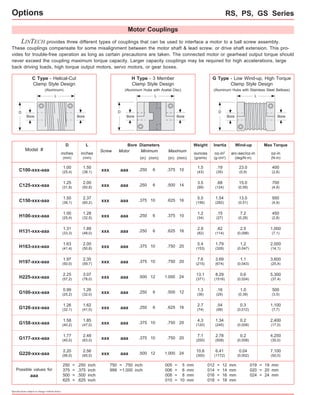


LINTECH provides three types of couplings (C, H, and G series) to interface motors to ball screw assemblies. The couplings compensate for misalignment and allow trouble-free operation if precautions are taken. The torque capacity of the coupling must exceed the connected motor or gearhead output torque. Larger capacity couplings may be required for applications with high accelerations, loads, torque outputs, or gearboxes.