More Related Content Similar to Shimpo er series Similar to Shimpo er series (20) More from Electromate (20) 1. 408
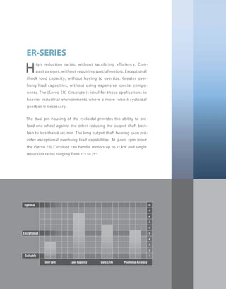
High reduction ratios, without sacrificing efficiency. Com-
pact designs, without requiring special motors. Exceptional
shock load capacity, without having to oversize. Greater over-
hung load capacities, without using expensive special compo-
nents. The (Servo ER) Circulute is ideal for those applications in
heavier industrial environments where a more robust cycloidal
gearbox is necessary.
The dual pin-housing of the cycloidal provides the ability to pre-
load one wheel against the other reducing the output shaft back-
lash to less than 6 arc-min. The long output shaft bearing span pro-
vides exceptional overhung load capabilities. At 3,000 rpm input
the (Servo ER) Circulute can handle motors up to 12 kW and single
reduction ratios ranging from 11:1 to 71:1.
ER-SERIES
2. 409
ER-SERIES
■ High efficiency cycloidal reducer design
■ Multiple inputs: NEMA C-Face, Servo Square Flange, Shaft Input,
Shovel Base, Top Mount
■ Straddle mount output shaft bearings (sizes D, E, F)
■ Multiple mounting options: Base, flange, ring
■ Readily available
■ Assembled in the USA
ER
3. 410
ER-SERIES Circulute 3000 cycloidal reducer
ER-Series – Features
2
1 Output shaft bearings
2 Output shaft
3 Internal pin housing
4 Internal pin
5 Wheels
6 Carrier pins
7 Input shaft
8 Eccentric roller bearings
9 Various mounting options
8
7
4
3
9
6
5
1
4. 411
ER
ER-Series – Model Code
Backlash
Quill Shaft Diameter
Quill Shaft Tolerance
(Specified by Shimpo)
(See Dimensional Table)
Mounting
Type Position
Modifications
(Use dashes for any place
not used - list modifications
in alphabetical order
using position one first)
Servo Motor Bolt Circle Diameter (mm)
Backlash
Servo Motor Input
Reduction Ratio (From the selection tables use dashes if all four places are not used)
Frame size (From the selection tables)
0B − − − −7 71 S 0 0 9 0 1 6 A B H
*1) Standard Backlash: Approximately 60 arc-min - 0
*2) Precision Backlash: Less than 6 arc-min - P
Contact us for additional information or refer to our online reducer selection tool.
Selection tool www.nidec-shimpo.co.jp/selection/eng
5. 412
ER-SERIES Circulute 3000 cycloidal reducer
Rating Table - 3000 rpm Input, Single Reduction, Precision Backlash (less than 6 arc-min)
*1) The reducer can continuously sustain this torque value without overheating
*2) The reducer can sustain this torque value for 1000 cycles without failure
*3) Acceleration torque is 1.5 times the nominal output torque
Frame Size Ratio Units Notes 11 17 29 35 47 59 71
B03
Input [kW] -- 1.430 1.160 0.710 0.560 0.390 0.320 0.250
Nominal Output Torque [Nm] *1 45.000 56.300 59.200 56.600 52.800 54.000 51.400
Emergency Stopping Torque [Nm] *2 112 141 148 141 132 135 128
Torsional Rigidity [Nm/arc-min] -- 3.000 4.700 5.000 5.400 5.400 5.400 5.400
Moment of Inertia [kg-cm2] -- 0.716 0.969 0.927 0.927 0.927 0.927 0.927
B07
Input [kW] -- 1.900 1.540 0.950 0.750 0.520 0.430 0.340
Nominal Output Torque [Nm] *1 60.000 75.000 78.900 75.400 78.200 79.900 76.100
Emergency Stopping Torque [Nm] *2 150 188 197 189 196 200 190
Torsional Rigidity [Nm/arc-min] -- 3.000 4.700 5.000 5.400 5.400 5.400 5.400
Moment of Inertia [kg-cm2] -- 0.716 0.969 0.927 0.927 0.927 0.927 0.927
C03
Input [kW] -- 2.910 2.690 1.690 1.550 1.080 0.860 0.710
Nominal Output Torque [Nm] *1 91.700 131 140 155 145 145 144
Emergency Stopping Torque [Nm] *2 229 328 350 388 362 362 361
Torsional Rigidity [Nm/arc-min] -- 6.200 11.200 11.900 12.600 12.600 12.600 12.600
Moment of Inertia [kg-cm2] -- 3.118 3.412 4.171 4.129 4.086 4.086 4.086
C07
Input [kW] -- 3.880 3.590 2.250 2.060 1.430 1.140 0.950
Nominal Output Torque [Nm] *1 122 175 187 207 214 214 214
Emergency Stopping Torque [Nm] *2 306 437 467 517 536 536 535
Torsional Rigidity [Nm/arc-min] -- 6.200 11.200 11.900 12.600 12.600 12.600 12.600
Moment of Inertia [kg-cm2] -- 3.118 3.412 4.171 4.129 4.086 4.086 4.086
D03
Input [kW] -- 6.830 5.380 3.400 3.010 2.240 1.720 1.360
Nominal Output Torque [Nm] *1 215 262 282 302 302 290 277
Emergency Stopping Torque [Nm] *2 538 654 705 754 754 725 693
Torsional Rigidity [Nm/arc-min] -- 17.800 23.000 25.200 27.400 27.400 27.400 27.400
Moment of Inertia [kg-cm2] -- 7.752 10.996 12.007 11.754 11.754 11.754 11.501
D07
Input [kW] -- 9.110 7.170 4.530 4.010 2.990 2.290 1.820
Nominal Output Torque [Nm] *1 287 349 376 402 447 430 411
Emergency Stopping Torque [Nm] *2 718 872 940 1,010 1,120 1,070 1,030
Torsional Rigidity [Nm/arc-min] -- 17.800 23.000 25.200 27.400 27.400 27.400 27.400
Moment of Inertia [kg-cm2] -- 7.752 10.996 12.007 11.754 11.754 11.754 11.501
6. 413
ER
Rating Table - 2000 rpm Input, Single Reduction, Precision Backlash (less than 6 arc-min)
*1) The reducer can continuously sustain this torque value without overheating
*2) The reducer can sustain this torque value for 1000 cycles without failure
*3) Acceleration torque is 1.5 times the nominal output torque
Frame Size Ratio Units Notes 11 17 29 35 47 59 71
E03
Input [kW] -- 13.100 11.600 9.710 8.050 5.390 4.430 3.420
Nominal Output Torque [Nm] *1 618 849 1,210 1,210 1,090 1,120 1,040
Emergency Stopping Torque [Nm] *2 1,540 2,120 3,030 3,030 2,730 2,800 2,600
Torsional Rigidity [Nm/arc-min] -- 54.800 70.400 85.200 85.200 85.200 85.200 85.200
Moment of Inertia [kg-cm2] -- 31.512 52.661 49.291 48.869 48.448 48.448 48.027
E07
Input [kW] -- 17.400 15.500 13.000 10.700 7.190 5.910 4.570
Nominal Output Torque [Nm] *1 824 1,130 1,610 1,610 1,450 1,500 1,390
Emergency Stopping Torque [Nm] *2 2,060 2,660 3,520 3,520 3,520 3,520 3,480
Torsional Rigidity [Nm/arc-min] -- 54.800 70.400 85.200 85.200 85.200 85.200 85.200
Moment of Inertia [kg-cm2] -- 31.512 52.661 49.291 48.869 48.448 48.448 48.027
F03
Input [kW] -- 20.200 19.900 17.000 14.800 10.800 8.170 6.790
Nominal Output Torque [Nm] *1 953 1,450 2,120 2,230 2,180 2,070 2,070
Emergency Stopping Torque [Nm] *2 2,380 3,630 5,300 5,580 5,450 5,180 5,180
Torsional Rigidity [Nm/arc-min] -- 116.700 122.300 133.400 133.400 133.400 133.400 133.400
Moment of Inertia [kg-cm2] -- 87.628 74.989 130.178 127.650 127.650 127.650 125.122
F07
Input [kW] -- 26.900 26.500 22.600 19.800 14.400 10.900 9.060
Nominal Output Torque [Nm] *1 1,270 1,940 2,820 2,970 2,900 2,760 2,760
Emergency Stopping Torque [Nm] *2 3,180 4,850 7,050 7,350 7,350 6,900 6,900
Torsional Rigidity [Nm/arc-min] -- 116.700 122.300 133.400 133.400 133.400 133.400 133.400
Moment of Inertia [kg-cm2] -- 87.628 74.989 130.178 127.650 127.650 127.650 125.122
7. 414
ER-SERIES Circulute 3000 cycloidal reducer
ER Common Dimensions – Single Stage Base Mount
*1) Sizes A through B do not have a lifting eye
T
L
Key
U
R
V
BA
F1
F
ØDF
Motor
Mounting
Flange
B
4-H
E
A
D
G
P
W
Frame Size Units A B BA D DF E F F1 G H P
A03 - A07 [mm] 175.01 119.89 65.28 89.99 N/A 145.03 89.92 14.99 16.00 11.94 147.07
A190 - A195 [mm] 180.09 134.87 59.94 100.00 N/A 150.11 89.92 14.99 11.94 10.92 147.07
B01 - B07 [mm] 175.01 150.11 85.85 115.01 N/A 145.03 119.89 14.99 16.00 11.94 150.11
B195 - B105 [mm] 180.09 134.87 59.94 100.00 N/A 150.11 89.92 14.99 11.94 10.92 150.11
B20H [mm] 180.09 134.87 59.94 119.99 N/A 150.11 89.92 14.99 11.94 10.92 150.11
C01 - C07 [mm] 219.96 189.99 103.38 140.00 N/A 180.09 150.11 20.07 22.10 14.99 189.99
C110 - C115 [mm] 230.12 154.94 82.04 119.99 N/A 189.99 115.06 20.07 14.99 13.97 189.99
C225 [mm] 230.12 154.94 82.04 140.00 N/A 189.99 115.06 20.07 14.99 13.97 189.99
D01 - D07 [mm] 275.08 230.12 135.38 165.00 N/A 225.04 180.09 24.89 25.91 19.05 234.95
D135 [mm] 330.20 195.07 100.08 149.99 N/A 290.07 145.03 24.89 22.10 18.03 234.95
D145 [mm] 330.20 195.07 119.89 149.99 N/A 290.07 145.03 24.89 22.10 18.03 234.95
D225 [mm] 330.20 195.07 119.89 159.99 N/A 290.07 145.03 24.89 22.10 18.03 233.68
E01 - E07 [mm] 359.92 299.97 150.88 184.99 312.93 299.97 249.94 24.89 29.97 22.10 299.97
E165 [mm] 409.96 238.00 138.94 159.99 312.93 369.82 150.11 43.94 24.89 18.03 299.97
E370 - E375 [mm] 430.02 335.03 124.97 200.00 312.93 379.98 275.08 29.97 29.97 22.10 414.02
F03 - F07 [mm] 424.94 365.00 194.82 210.01 368.05 350.01 294.89 35.05 35.05 24.89 359.92
8. 415
ER
ER Flange Dimensions – Single Stage Base Mount
*1) Other servo flanges and bore sizes are available.
Contact Shimpo Drives Customer Service for
additional information
*2) All dimensions are in mm, except for «R»
dimension, which is in inches
*3) To download CAD drawings, visit our website:
www.shimpodrives.com
*4) The "R" dimension is the length from input flange
face to output shaft end
Motor Mounting FlangeCircleSquare
Frame Size LC LD LF LG LH LN LJ MH ML R
Net Weight
(kg)
A03 - A07
70 -- 5 5 50 120 M5 14, 16 37 202.692 9.98
90 -- 5 7 70 120 M6 16, 19 57 212.60 9.98
100 -- 7 7 80 120 M6 16, 19 -- 214.63 9.98
115 100 7 7 95 -- M6 19, 24 57 212.60 9.98
145 110 7 8 110 -- M8 22, 24 -- 212.60 12.70
B03 - B07
70 -- 5 5 50 120 M5 14, 16 37 238.00 16.33
90 -- 5 7 70 120 M6 16, 19 57 247.90 16.33
100 -- 7 7 80 120 M6 16, 19 -- 249.94 16.33
115 100 7 7 95 -- M6 19, 24 57 247.90 16.33
145 110 7 8 110 -- M8 22, 24 -- 247.90 17.23
C03 - C07
90 -- 7 7 70 160 M6 16 -- 293.88 30.84
100 -- 7 7 80 120 M6 16, 19 -- 300.99 30.84
115 130 7 7 95 -- M6 22, 24 -- 293.88 30.84
145 130 7 8 110 -- M8 24, 28 -- 293.88 30.84
200 176 7 7 114.3 -- M12 28, 35 -- 328.93 38.55
D03 - D07
115 -- 7 7 95 200 M6 22, 24 -- 354.08 52.15
145 130 8 8 110 -- M8 22, 24 -- 349.00 52.15
165 -- 8 8 130 200 M10 24, 28 -- 360.93 52.15
200 176 10 7 114.3 -- M12 28, 35 -- 378.97 56.69
215 -- 10 10 180 300 M12 35, 38 -- 399.03 61.22
E03 - E07
145 -- 10 7 110 250 M8 24, 28 -- 409.96 111.56
165 176 7 7 130 -- M12 24, 28 -- 399.03 101.59
200 176 7 6 114.3 -- M12 28, 35 -- 399.03 101.59
215 -- 10 11 180 300 M12 35, 38 -- 459.99 116.55
235 -- 8 11 200 350 M12 38, 42 -- 494.03 129.71
F03 - F07
200 -- 10 7 114.3 300 M12 28, 35 -- 546.10 207.71
215 -- 10 8 180 300 M12 35, 38 -- 546.10 207.71
235 -- 5 11 200 300 M12 38, 42 -- 546.10 207.71
265 -- 5 11 230 400 M12 42, 48 -- 564.90 219.50
MH AU AW ML
14 16 5 32
16 18 5 37
19 21.5 6 42
22 25 8 57
24 27 8 67
MH AU AW ML
28 31 8 67
35 38 10 67
38 41 10 88
42 45 12 118
48 51.5 14 118
9. 416
ER-SERIES Circulute 3000 cycloidal reducer
ER Common Dimensions – Single Stage Flange Mount
HO
AG
C
BDØ
R
BBBE
AMØ
AG
L
T
U
UA
Key
Key
BH
V
VA
DFØ
Motor
Mounting
Flange
Shaft
Input
Sizes D01-F07
Sizes A03-C07
BF Hole Diameter
BG Number of Holes
BF Hole Diameter
BG Number of Holes
Output Flange
Output Shaft
Input Shaft
Frame Size Units AG AM BB BD BE BF BG BH HO
A03 - A07 [mm] 130.05 110.01 4.06 160.02 13.97 11.94 101.60 29.97 N/A
B01 - B07 [mm] 165.10 130.00 4.06 199.90 13.97 11.94 101.60 40.13 N/A
C01 - C07 [mm] 214.88 180.01 4.06 249.94 18.03 14.99 101.60 55.12 N/A
D01 - D07 [mm] 264.92 230.00 5.08 299.97 22.10 14.99 203.20 70.10 184.91
E01 - E07 [mm] 350.01 300.00 7.87 400.05 24.89 19.05 203.20 89.92 230.12
F03 - F07 [mm] 400.05 350.01 7.87 450.09 24.89 19.05 203.20 109.98 260.10
Frame Size Units
Output Shaft
U V Key T L
A03 - A07 [mm] 22.23 30.23 4.78x4.78x24.89 N/A N/A
B01 - B07 [mm] 34.925 50.80 7.95x7.95x44.96 N/A N/A
C01 - C07 [mm] 44.450 63.50 9.53x9.53x54.86 N/A N/A
D01 - D07 [mm] 63.500 95.25 15.88x15.88x74.93 M10 x 1.5 18.03
E01 - E07 [mm] 73.025 111.00 19.05x19.05x95.00 M20 x 2.5 35.05
F03 - F07 [mm] 92.075 139.70 22.23x22.23x115.06 M20 x 2.5 35.05
10. 417
ER
ER Flange Dimensions – Single Stage Flange Mount
ML
LG
LH
LF
(SQUARE)
4-LJLD
AW
LC
MH
AU
LH
LF
ML
LG
(CIRCLE)
4-LJ
AU
LC
MH
LN
AW
R
Motor
Mounting
Flange
*1) Other servo flanges and bore sizes are available.
Contact Shimpo Drives Customer Service for
additional information
*2) All dimensions are in mm, except for «R»
dimension, which is in inches
*3) To download CAD drawings, visit our website:
www.shimpodrives.com
Frame Size LC LD LF LG LH LN LJ MH ML R
Net Weight
(kg)
A03 - A07
70 -- 5 5 50 120 M5 14, 16 37 202.69 9.98
90 -- 5 7 70 120 M6 16, 19 57 212.60 9.98
100 -- 7 7 80 120 M6 16, 19 -- 214.63 9.98
115 100 7 7 95 -- M6 19, 24 57 212.60 9.98
145 110 7 8 110 -- M8 22, 24 -- 212.60 12.70
B03 - B07
70 -- 5 5 50 120 M5 14,16 37 238.00 16.33
90 -- 5 7 70 120 M6 16, 19 57 247.90 16.33
100 -- 7 7 80 120 M6 16, 19 -- 249.94 16.33
115 100 7 7 95 -- M6 19, 24 57 247.90 16.33
145 110 7 8 110 -- M8 22, 24 -- 247.90 17.23
C03 - C07
90 -- 7 7 70 160 M6 16 -- 293.88 30.84
100 -- 7 7 80 120 M6 16, 19 -- 300.99 30.84
115 130 7 7 95 -- M6 22, 24 -- 293.88 30.84
145 130 7 8 110 -- M8 24, 28 -- 293.88 30.84
200 176 7 7 114.3 -- M12 28, 35 -- 328.93 38.55
D03 - D07
115 -- 7 7 95 200 M6 22, 24 -- 354.08 52.15
145 130 8 8 110 -- M8 22, 24 -- 349.00 52.15
165 -- 8 8 130 200 M10 24, 28 -- 360.93 52.15
200 176 10 7 114.3 -- M12 28, 35 -- 378.97 56.69
215 -- 10 10 180 300 M12 35, 38 -- 399.03 61.22
E03 - E07
145 -- 10 7 110 250 M8 24, 28 -- 409.96 111.56
165 176 7 7 130 -- M12 24, 28 -- 399.03 101.59
200 176 7 6 114.3 -- M12 28, 35 -- 399.03 101.59
215 -- 10 11 180 300 M12 35, 38 -- 459.99 116.55
235 -- 8 11 200 350 M12 38, 42 -- 494.03 129.71
F03 - F07
200 -- 10 7 114.3 300 M12 28, 35 -- 546.10 207.71
215 -- 10 8 180 300 M12 35, 38 -- 546.10 207.71
235 -- 5 11 200 300 M12 38, 42 -- 546.10 207.71
265 -- 5 11 230 400 M12 42, 48 -- 564.90 219.50
MH AU AW ML
14 16 5 32
16 18 5 37
19 21.5 6 42
22 25 8 57
24 27 8 67
MH AU AW ML
28 31 8 67
35 38 10 67
38 41 10 88
42 45 12 118
48 51.5 14 118