SlideShare a Scribd company logo
1 of 47
Download to read offline
Cup Type Component Sets & Housed Units 
CSD & SHD 
Series 
Total Motion Control 
Harmonic Drive™gear P r e c i s i o n G e a r i n g a n d M o t i o n C o n t r o l
Sold & Serviced By: 
­­­­­­­­­­­2 
SHD Series 
ELECTROMATE 
Toll Free Phone (877) SERVO98 
Toll Free Fax (877) SERV099 
www.electromate.com 
sales@electromate.com
SHD Series 
Harmonic Drive™ Gear 
Contents 
­­­­­­­­­­­3 
­­­­­­­­­­­2 
ABOUT HARMONIC DRIVE CSD & SHD 
Ordering Information 4 
Harmonic Drive Gearing Mechanism Principle & Structure 5 
Driving Configurations 6 
Application Examples 7 
CSD Rating Table 8 
SHD Rating Table 9 
Technical Terms, Strength & Life 10 
Technical Terms, Life & Torque 11 
Selection Procedure & example 12 
COMPONENT TYPE CSD 
CSD External Dimension & Shape 14 
Lubrication 16 
Recommended Tolerances for Assembly 19 
Wave Generator Assembly Notes for CSD 20 
Assembly of the Flexspline 21 
Assembly of the Circular Spline, Assembly Notes 22 
CSD Assembly Procedure 23 
HOUSED UNIT TYPE SHD 
SHD External Dimensions of Housed Unit 24 
Specifications for Cross Roller Bearing 26 
Output Bearing Calculations 27 
Output Bearing Life 28 
Lubrication 29 
Recommended Tolerances for Assembly 30 
SHD Assembly Notes and Procedure 35 
ENGINEERING DATA CSD & SHD 
Efficiency of Component Set 36 
Efficiency of Housed Unit 37 
No Load Running Torque 38 
Starting Torque and Backdriving Torque 40 
Positioning Accuracy 41 
Torsional Stiffness 41 
Hysteresis Loss 43 
Harmonic Drive LLC 800-921-3332 
Sold & Serviced By: 
ELECTROMATE 
Toll Free Phone (877) SERVO98 
Toll Free Fax (877) SERV099 
www.electromate.com 
sales@electromate.com
Sold & Serviced By: 
­­­­­­­­­­­4 
SHD Series 
4 
S Series CSF Series CSD & SHD Series 
Ordering Code 
Ordering Information 
CSD 
Name of Model Size Ratio Model 
14 50, 100 
17 50, 100 
20 50, 100, 160 2A-GR: Component Type None: Standard 
CSD 25 50, 100, 160 (size 14 and 17 
32 50, 100, 160 are 2A-R) 
40 50, 100, 160 BB: Big Bore 
50 50, 100, 160 on Flexspline 
14 50, 100 (CSD Series) 
17 50, 100 
SHD 20 50, 100, 160 2SH 
25 50, 100, 160 Simplicity Unit Type SP: Special 
32 50, 100, 160 
40 50, 100, 160 
Evolution of Harmonic Drive™ Gear Revolution 
Harmonic Drive™ precision gear continues to evolve by improving performance and functionality. 
By pursuing strength and The CSF achieved a 
stiffness, a new tooth profile reduction in axial length 
was invented. The “S” tooth of approximately 50% Achieve another axial 
doubled torque, life and stiffness length reduction of 
approximately 50% 
ELECTROMATE 
Toll Free Phone (877) SERVO98 
Toll Free Fax (877) SERV099 
www.electromate.com 
sales@electromate.com
About Harmonic DSriHveD™ S Gereiaers 
Principle and Structure 
Sold & Serviced By: 
ELECTROMATE 
Toll Free Phone (877) SERVO98 
Toll Free Fax (877) SERV099 
5 
­­­­­­­­­­­5 
Outer Cross 
Roller Bearing 
(Output) 
0 º 
SHD CSD 
Circular Spline 
Wave Generator 
Flexspline 
Wave Generator 
www.electromate.com 
sales@electromate.com 
90º 360º 
The Flexspline is elliptically shaped by The 
Wave Generator and engaged with the 
Circular Spline at the major elliptical axis. 
The teeth completely disengage on the 
minor axis. 
For each 360 degrees clockwise 
movement of the Wave Generator, the 
Flexspline moves counterclockwise by 
two teeth relative to the Circular Spline. 
When the Circular Spline is fixed and 
the Wave Generator rotates clockwise, 
the Flexspline is elastically deformed 
and rotates counterclockwise relative to 
the Circular Spline. 
Circular Spline 
Wave Generator 
Cross Roller Bearing 
Flexspline 
Bolt 
(temporary) 
Flexspline 
Circular Spline 
Circular Spline 
Flexspline 
Wave Generator 
System Components 
The FLEXSPLINE is a non-rigid, steel cylindrical cup with external teeth on a slightly smaller pitch diameter than the Circular Spline. 
It fits over and is held in an elliptical shape by the Wave Generator. 
The WAVE GENERATOR is a thin raced ball bearing fitted onto an elliptical plug serving as a high efficiency torque converter. 
The CIRCULAR SPLINE is a rigid ring with internal teeth, engaging the teeth of the Flexspline across the major axis of the Wave Generator.
Driving Configurations 
A variety of different driving configurations 
are possible, as shown below. 
The reduction ratio R, given in the tables 
on page 7 and 8 correspond to 
arrangement 1, in which the 
Wave Generator acts as the 
input element, the Circular Spline 
is fixed and the Flexspline 
acts as the output element. 
­­­­­­­­­­­6 
About Harmonic DSriHveD™ S Gereiaers 
Driving Configurations 
6 
Ratio = input speed 
output speed 
3. Reduction Gearing 
WG Fixed 
FS Input 
CS Output 
R + 1 
Ratio = R [Equation 3] 
Input and output in same direction. 
6. Speed Increaser Gearing 
FS Fixed 
CS Input 
WG Output 
1 
Ratio = R + 1 [Equation 6] 
Input and output in same direction. 
1. Reduction Gearing 
CS Fixed 
WG Input 
FS Output 
Ratio = — R 1 
[Equation 1] 
Input and output in opposite direction. 
4. Speed Increaser Gearing 
WG Fixed 
CS Input 
FS Output 
R 
Ratio = R + 1 [Equation 4] 
Input and output in same direction. 
7. Differential Gearing 
WG Control Input 
CS Main Drive-Input 
FS Main Drive-Output 
Numerous differential functions can 
be obtained by combinations of the 
speed and rotational direction of 
the three basic elements. 
2. Reduction Gearing 
FS Fixed 
WG Input 
CS Output 
R + 1 
Ratio = 1 [Equation 2] 
Input and output in same direction. 
5. Speed Increaser Gearing 
CS Fixed 
FS Input 
WG Output 
Ratio = — 1 R 
[Equation 5] 
Input and output in opposite direction. 
Sold & Serviced By: 
ELECTROMATE 
Toll Free Phone (877) SERVO98 
Toll Free Fax (877) SERV099 
www.electromate.com 
sales@electromate.com
Application Examples 
About Harmonic DSriHveD™ S Gereiaers Wave Generator 
­­­­­­­­­­­7 
Flexspline 
Circular Spline 
Simplicity Unit 
Circular Spline 
Flexspline 
Output 1 
Output 2 
Wave Generator 
Flexspline (SHD) 
CSD Series 
Rotary Table for Machine Tool 
SHD Series 
SCARA 
CSD • SHD Series 
2 Axis - Output Unit 
Harmonic Drive LLC 800-921-3332 7 
Sold & Serviced By: 
ELECTROMATE 
Toll Free Phone (877) SERVO98 
Toll Free Fax (877) SERV099 
www.electromate.com 
sales@electromate.com
Sold & Serviced By: 
­­­­­­­­­­­8 
SHD Series 
8 
Table 1 
CSD Gear Rated Limit for Limit for Limit for Maximum Limit for Moment 
Size Ratio Torque Repeated Average Momentary Input Average of 
at Peak Torque Peak Speed Input Inertia 
R 2000 Torque Torque Speed 
Tr 
rpm Nm Nm Nm rpm rpm I J 
Nm in-lb Nm in-lb Nm in-lb Nm in-lb Oil Grease Oil Grease x10-4kg•m2 x10-5kgf•m•s2 
14 50 3.7 33 12 106 4.8 42 24 212 14000 8500 6500 3500 0.021 0.021 
100 5.4 48 19 168 7.7 68 31 274 
17 50 11 97 23 204 18 159 48 425 10000 7300 6500 3500 0.054 0.055 
100 16 142 37 327 27 239 55 487 
50 17 150 39 345 24 212 69 611 
20 100 28 248 57 504 34 301 76* 673* 10000 6500 6500 3500 0.090 0.092 
(65) (575) 
160 28 248 64 566 34 301 76* 673* 
(65) (575) 
50 27 239 69 611 38 336 127 1124 
(135) (1195) 
25 100 47 416 110 974 75 664 152* 1345* 7500 5600 5600 3500 0.282 0.288 
(135) (1195) 
160 47 416 123 1089 75 664 152* 1345* 
50 53 469 151 1336 75 664 268 2372 
(331) (2929) 
32 100 96 850 233 2062 151 1336 359* 3177* 7000 4800 4600 3500 1.09 1.11 
(331) (2929) 
160 96 850 261 2310 151 1336 359* 3177* 
50 96 850 281 2487 137 1212 480 4248 
(580) (5133) 
40 100 185 1637 398 3522 260 2301 694* 6142* 5600 4000 3600 3000 2.85 2.91 
(580) (5133) 
160 206 1823 453 4009 316 2797 694* 6142* 
50 172 1522 500 4425 247 2186 1000 8850 
(1315) (11638) 
50 100 329 2912 686 6071 466 4124 1440 12744 4500 3500 3000 2500 8.61 8.78 
(1315) (11638) 
160 370 3275 823 7284 590 5222 1577* 13956* 
Note: The moment of inertia : I=1/4GD2, measured at the input 
The momentary peak torque is limited by tightening torque on the flexspline. 
The values in parenthesis are values in the case of the Big Bore option on the flexspline. 
About Harmonic Drive™ Gear 
CSD Rating Table 
ELECTROMATE 
Toll Free Phone (877) SERVO98 
Toll Free Fax (877) SERV099 
www.electromate.com 
sales@electromate.com
About Harmonic DSriHveD™ S Gereiaers 
SHD Rating Table 
Table 2 
­­­­­­­­­­­9 
SHD Ratio Rated Limit for Limit for Limit for Maximum Limit for Moment 
Size Torque Repeated Average Momentary Input Average of 
R at Peak Torque Peak Speed Input Inertia 
2000 Torque Torque Speed 
Tr 
rpm Nm Nm Nm rpm rpm I J 
Nm in-lb Nm in-lb Nm in-lb Nm in-lb Grease Grease x10-4kg•m2 x10-5kgf•m•s2 
14 50 3.7 33 12 106 4.8 42 23 204 8500 3500 0.021 0.021 
100 5.4 48 19 168 7.7 68 35 310 
17 50 11 97 23 204 18 159 48 425 7300 3500 0.054 0.055 
100 16 142 37 327 27 239 71 628 
50 17 150 39 345 24 212 69 611 
20 100 28 248 57 504 34 301 95 841 6500 3500 0.090 0.092 
160 28 248 64 566 34 301 95 841 
50 27 239 69 611 38 336 127 1124 
25 100 47 416 110 974 75 664 184 1628 5600 3500 0.282 0.288 
160 47 416 123 1089 75 664 204 1805 
50 53 469 151 1336 75 664 268 2372 
32 100 96 850 233 2062 151 1336 420 3717 4800 3500 1.09 1.11 
160 96 850 261 2310 151 1336 445 3938 
50 96 850 281 2487 137 1212 480 4248 
40 100 185 1637 398 3522 260 2301 700 6195 4000 3000 2.85 2.91 
160 206 1823 453 4009 316 2797 765 6770 
Note: The moment of inertia : I=1/4GD2, measured at the input. 
Harmonic Drive LLC 800-921-3332 9 
Sold & Serviced By: 
ELECTROMATE 
Toll Free Phone (877) SERVO98 
Toll Free Fax (877) SERV099 
www.electromate.com 
sales@electromate.com
About Harmonic DSriHveD™ S Gereiaers 
Technical Terms Strength & Life 
Definition of Ratings 
Rated Torque (Tr) 
Rated torque indicates allowable continuous load torque at 
2000 rpm input speed. 
Limit for Repeated Peak Torque (refer to figure 1) 
During acceleration a deceleration the Harmonic Drive™ gear experi-ences 
Sold & Serviced By: 
­­­­­­­­­­­10 
10 
a peak torque as a result of the moment of 
inertia of the output load. The table indicates the limit for 
repeated peak torque. 
Limit for Average Torque 
In cases where load torque and input speed vary, it is necessary 
to calculate an average value of load torque. The table indicates 
the limit for average torque. The average torque calculated 
must not exceed this limit. 
Limit for Momentary Peak Torque (refer to figure 1) 
The gear may be subjected to momentary peak torques in the 
event of a collision or emergency stop. The magnitude and frequency 
of occurrence of such peak torques must be kept to a minimum and 
they should, under no circumstance, occur during normal operating 
cycle. The allowable number of occurrences of the momentary peak 
torque may be calculated by using equation 1. Also see section 
“strength and life”. 
Figure 1 
S t a r t 
Routine 
Stop 
Abnormal Impact To rque 
Maximum Input Speed, Limit for average input speed 
Do not exceed the allowable rating. 
Moment of Inertia 
The rating indicates the moment of inertia reflected to the 
wave generator (gear input). 
Strength and Life 
The non-rigid Flexspline is subjected to repeated deflections, and its 
strength determines the torque capacity of the Harmonic Drive™ gear. 
The values given for Rated Torque at Rated Speed and for the allo-wable 
Repeated Peak Torque are based on an infinite fatigue 
life for the Flexspline. 
The torque that occurs during a collision must be below the momenta-ry 
peak torque (impact torque). The maximum number 
of occurrences is given by the equation below. 
[Equation 1] 
1.0 X 10⁴ n: Input speed before collision 
N = ____________ 
2 X n 
60 X t t: Time interval during collision 
Please note: 
If this number is exceeded, the Flexspline may experience 
a fatigue failure. 
Ratcheting phenomenon 
When excessive torque is applied while the gear is in motion, the 
teeth between the Circular Spline and Flexspline may not engage pro-perly. 
This phenomenon is called ratcheting and the torque at which 
this occurs is called ratcheting torque. Ratcheting may cause the 
Flexspline to become non-concentric with the Circular Spline. (See 
figure 1 & 2 on page 12) Operating in this condition may result in 
shortened life and a Flexspline fatigue failure. 
Figure 2 
Circular Spline 
Flexspline 
This condition is called “dedoidal”. 
Note! 
When ratcheting occurs, the teeth mesh abnormally as shown above. 
Vibration and Flexspline damage may occur. 
Once ratcheting occurs, the teeth wear excessively and the 
ratcheting torque may be lowered. 
Speed Cycle 
S t a r t 
T ime 
T ime 
Load To rque 
Load To rque 
Repeated Peak To rque 
Momentary Peak To rque 
Number of Rotations 
of Wave Generator 
ELECTROMATE 
Toll Free Phone (877) SERVO98 
Toll Free Fax (877) SERV099 
www.electromate.com 
sales@electromate.com
Life Technical Terms 
­­­­­­­­­­­11 
SHD Series 
Table 6 Buckling Torque Nm 
SHD 
Size All Ratio 
14 130 
17 260 
20 470 
25 850 
32 1800 
40 3600 
Repeated Peak Torque 
Harmonic Drive LLC 800-921-3332 
The Life of a Wave Generator 
The normal life of a gear is determined by the life of the wave 
generator bearing. The life may be calculated by using the input 
speed and the output load torque. 
Rated Lifetime Ln : (n = 10 or 50) , hours 
L10 CSD,SHD: 7,000 
L50 CSD,SHD: 35,000 
Equation for the expected life of the wave generator under 
normal operating conditions is given by the equation below. 
[Equation 2] 
Lh = Ln • ( Tr )3 
• ( Nr ) Tav Nav 
Lh : Expected Life, hours 
Ln : Rated Lifetime at L10 or L50 , hours 
Tr : Rated Torque (Tables 1, 2, 3) 
Nr : Rated input speed (2000 rpm) 
Tav : Average load torque on output side (page 14) 
Nav : Average input speed (page 14 
Relative Torque Rating 
The chart below shows the various torque specifications 
relative to rated torque. Rated Torque has been 
normalized to 1 for comparison. 
Figure 3 
17 
16 
10 
9 
8 
7 
6 
5 
4 
3 
2 
1 
105 0 
Buckling Torque 
Racheting Torque 
Fatique Strength of Flexspline 
Life of the Wave Generator(L10) 
106 107 108 109 1010 
Total Number of Input Rotations 
Load Torque (Rated Torque = 1) 
Rated Torque 
NON-OPERATING ZONE 
NORMAL 
OPERATING ZONE 
Momentary Peak Torque 
SHD Ratcheting Torque Table 5 Nm 
Size Ratio 
50 100 160 
14 88 84 – 
17 150 160 – 
20 220 260 220 
25 450 500 450 
32 980 1000 980 
40 1800 2100 1800 
Table 4 Buckling Torque Nm 
CSD 
Size All Ratio 
14 190 
17 330 
20 560 
25 1000 
32 2200 
40 4300 
50 8000 
CSD Ratcheting Torque Table 3 Nm 
Size Ratio 
50 100 160 
14 88 84 – 
17 150 160 – 
20 220 260 220 
25 450 500 450 
32 980 1000 980 
40 1800 2100 1800 
50 3700 4100 3600 
11 
About Harmonic Drive™ Gear 
Sold & Serviced By: 
ELECTROMATE 
Toll Free Phone (877) SERVO98 
Toll Free Fax (877) SERV099 
www.electromate.com 
sales@electromate.com
SHD Series 
Sold & Serviced By: 
­­­­­­­­­­­12 
12 
Torque rpm 
t1 
T1 
T2 
T3 
T4 
Tn 
t2 t3 t4 tn 
n1 n3 
n4 
nn 
n2 
Time 
n1 n2 nn are an average value. Time NG 
OK 
OK 
OK 
OK 
OK 
NG 
NG 
NG 
NG 
Size Selection 
Generally, the operating conditions consist of fluctuating torques 
and output speeds. Also, an unexpected impact output torque 
must be considered. 
The proper size can be determined by converting fluctuating load 
torque into average load torque and equivalent load torque. This 
procedure involves selecting the size based on load torque for com-ponent 
sets. 
This procedure does not consider the life of the output bearing for 
housed units. Determining the life of the output bearing for various 
axial, radial, and moment loads is outlined on page 25. 
Figure 4 
Parameters 
Load Torque Tn (Nm) 
Time tn (sec) 
Output Speed nn (rpm) 
Normal Operating Pattern 
Acceleration T1,t1, n1 
Regular Operation T2,t2, n2 
Deceleration T3,t3, n3 
Dwell T4,t4, n4 
Maximum RPM 
Max output speed no maximum 
Max input speed ni maximum 
Impact Torque Ts,ts, ns 
Ratings 
Rated Torque Tr 
Rated Speed nr =2000 rpm 
Flow Chart for selecting a size 
Please use the flowchart shown below for selecting a size. 
Operating conditions must not exceed the performance 
ratings as described on page 12. 
Calculation of the average output torque 
Tav = 3 n1•t1•|T1| 3+n2•t2•|T2| 3+... nn•tn•|Tn| 3 
n1•t1+n2•t2+... nn tn 
Selection of tentative size under the 
condition shown below. 
Average Output Speed 
no av = 
n1•t1•n2•t2+... nntn 
t1+t2•t2+...tn 
Determine Gear Ratio 
ni max 
<= R 
no max 
ni max may be limited by the motor. 
Calculation of the average input speed 
ni av = no av •R 
Calculation of maximum input speed 
ni max = no max •R 
ni av <= Limit for average speed 
ni max <= Limit for maximum speed 
Confirm if T1 and T3 are less than the 
repeated peak torque specification. 
Confirm if Ts (impact torque) is less than 
the momentary peak torque specification. 
Calculate the allowable number of rotations 
during impact torque. 
Ns = 104 
••••••Ns <= 1.0X10⁴ 
2• 
ns•R 
•ts 60 
Calculate wave generator life. 
Lh = Ln • ( Tr )3 
•( nr ) Tav ni av 
Make sure that the calculated life is suitable 
for the application. 
Gear is suitable for torque and speed requirements 
Also consider output bearing, environment, etc. 
Consider a different size or change operating requirements 
About Harmonic Drive™ Gear 
Selection Procedure 
ELECTROMATE 
Toll Free Phone (877) SERVO98 
Toll Free Fax (877) SERV099 
www.electromate.com 
sales@electromate.com
Selection Example 
­­­­­­­­­­­13 
About Harmonic DSriHveD™ S Gereiaers 
Values of an each Load Torque Pattern 
Load Torque Tn (Nm) no max = 14 rpm 
Time tn (sec) ni max = 1800 rpm 
Output Speed nn (rpm) 
Normal Operating Pattern 
Acceleration T1 = 400 Nm, t1 = 0.3 sec, n1 = 7 rpm Ts = 500 Nm, ts = 0.15 sec, ns = 14 rpm 
Regular Operation Stop T2 = 320 Nm, t2 = 3 sec, n2 = 14 rpm 
Deceleration T3 = 200 Nm, t3 = 0.4 sec, n3 = 7 rpm L10 > 7000 hrs. 
Dwell T4 = 0 Nm, t4 = 0.2 sec, n4 = 0 rpm Oil Lubrication 
OK 
OK 
OK 
OK 
OK 
NG 
NG 
NG 
NG 
NG 
Tav (Nm) 
Tav = 3 7rpm•0.3sec•| 400Nm| 3+14rpm•3sec•|320Nm| 3+7rpm•0.4sec•|200Nm| 3 
7rpm•0.3sec+14rpm•3sec+7rpm•0.4sec 
Tav = 319Nm<466Nm (for CSD-50-100-2A-GR) 
no av (rpm) 
7rpm•0.3sec+14rpm•3sec+7rpm•0.4sec = 12 rpm 
•0.3sec+3sec+0.4sec+0.2sec 
(R) 
1800 RPM = 128.6>100 14 rpm 
ni av = 12rpm•100=1200rpm 
no max ni max (rpm) 
ni max = 14rpm•100=1400rpm 
ni av =1440rpm<3600rpm (for CSD-50-100-2A-GR) 
ni max =1680rpm<5600rpm (for CSD-50-100-2A-GR) 
Confirm that T1 and T3 are within a 
T1, T3 (Nm) 
T1 = 400Nm<686Nm (for CSD-50-100-2A-GR) 
T3 = 200Nm<686Nm (for CSD-50-100-2A-GR) 
TS (Nm) 
TS ) = 500Nm<1440Nm (for CSD-50-100-2A-GR) 
NS Calculate an allowable number of rotation(Ns) and confirm <= 1.0 x 10⁴ 
NS = 104 NS =1429<1.0 x 10⁴ 
2 • 14rpm•100 • 0.15 
60 
Calculate a life time. 
L10 = 7000 (329Nm)3 (2000rpm) 
1319Nm • 1440rpm 
L10 = 10665 > 7000 (LB10) 
CSD-50-100-2A-GR 
Consider a different size or change operating requirements 
Harmonic Drive LLC 800-921-3332 13 
Sold & Serviced By: 
ELECTROMATE 
Toll Free Phone (877) SERVO98 
Toll Free Fax (877) SERV099 
www.electromate.com 
sales@electromate.com
SHD Series 
Sold & Serviced By: 
­­­­­­­­­­­14 
14 
*2 
1 2 3 1 2 1 3 
C0.4 
G 
1 Ball Separator 
2 Wave Generator Bearing 
3 Wave Generator Plug 
Size: 14, 17 Size: 20, 25, 32, 40, 50 
U-øV 
øZ3 
øT 
G1 
Expanded G Section 
L-øM 
2-N 
øZ1 
15º 
øZ2 4-S 
øQ 
øR 
C 
D F 
E 
O 
b 
c 
4 
øAh7 
C0.5 
C0.5 
C0.3 
1 
1 
3 
øa 
øP 
øBH7 
øK H6 
øJ 
øa 
H 
A 
1. #14 and 17 are co.4. 
2. #40 and 50 are co.5. 
3. #14 is 30º, #17 is 22.5º. 
4. #14 ‑32 are co.3, #40 and #50 are co.5. 
*1 
**4 
Outside appearance varies depending on size. 
CSD Series 
CSD External Dimension & Shape 
ELECTROMATE 
Toll Free Phone (877) SERVO98 
Toll Free Fax (877) SERV099 
www.electromate.com 
sales@electromate.com
CSD External Dimension & Shape 
­­­­­­­­­­­15 
SCHSD Seerriieess 
CSD Dimensions Table 7 unit: (mm) 
Size 14 17 20 25 32 40 50 
øA h7 50 0 
-0.025 60 0 
-0.030 70 0 
-0.030 85 0 
-0.035 110 0 
-0.035 135 0 
-0.040 170 0 
-0.040 
øBH7 11+0.018 
0 15+0.018 
0 20+0.021 
0 24+0.021 
0 32+0.025 
0 40+0.025 
0 50+0.025 
0 
C 11 12.5 14 17 22 27 33 
D 6.5+0.2 
0 7.5+0.2 
0 8 +0.3 
0 10+0.3 
0 13+0.3 
0 16+0.3 
0 19.5+0.3 
0 
E 1.4 1.7 2 2 2.5 3 3.5 
F 4.5 5 6 7 9 11 13.5 
G1 0.3 0.3 0.3 0.4 0.5 0.6 0.8 
H 4 5 5.2 6.3 8.6 10.3 12.7 
øJ 23 27.2 32 40 52 64 80 
øK H6 11+0.011 
0 11+0.011 
0 16+0.011 
0 20+0.013 
0 30+0.013 
0 32+0.016 
0 44+0.016 
0 
L 6 8 12 12 12 12 12 
øM 3.4 3.4 3.4 3.4 4.5 5.5 6.6 
N M3 M3 M3 M3 M4 M5 M6 
O _ _ 3.3 3.3 4.4 5.4 6.5 
øP _ _ 6.5 6.5 8 9.5 11 
øQ 44 54 62 75 100 120 150 
øR 17 21 26 30 40 50 60 
S M3 M3 M3 M3 M4 M5 M6 
øT 17 19.5 24 30 41 48 62 
U 9 8 9 9 11 10 11 
øV 3.4 4.5 4.5 5.5 6.6 9 11 
øZ0.2 0.2 0.2 0.2 0.25 0.25 0.3 
1 øZ0.25 0.25 0.2 0.2 0.25 0.25 0.3 
2 øZ0.2 0.25 0.25 0.25 0.3 0.5 0.5 
3 øa 
38 45 53 66 86 106 133 
b 6.5 7.5 8 10 13 16 19.5 
c 1 1 1.5 1.5 2 2.5 3.5 
Minimum 
housing 
clearance 
weight (kg) 0.06 0.10 0.13 0.24 0.51 0.92 1.9 
Weight 
Note: Standard dimension for size 14 and 17 is the maximum bore. 
Dimensions for BB Table 8 unit:mm 
Size 20 25 32 40 50 
ø KH6 20+0.013 
0 24+0.013 
0 32+0.016 
0 40+0.016 
0 50+0.016 
0 
U 12 12 12 14 14 
ø V 3.4 4.5 5.5 6.6 9 
ø T 26 32 42 52 65 
ø Z3 0.2 0.25 0.25 0.3 0.5 
• Installed surface on Circular Spline is shown as A. 
Use this surface for installation in case. 
• Dimensions shown below may be modified as a special order. 
B: Dimension of Wave generator 
U and V: Dimension of Flexspline 
L and M: Dimension of Circular spline 
• Dimensions for C•D•G must meet the tolerance 
values shown above. 
• øa, b, c must exceed the values shown above due to 
deformation of the flexspline. 
Harmonic Drive LLC 800-921-3332 15 
Note: Standard dimension for size 14 and 17 is the maximum bore. 
Sold & Serviced By: 
ELECTROMATE 
Toll Free Phone (877) SERVO98 
Toll Free Fax (877) SERV099 
www.electromate.com 
sales@electromate.com
SHD Series 
Lubricant 
Grease lubricant is the standard for the CSD unit. The temperature range is shown below. (Exceptions are shown on page 17.) 
Lubricant 
Grease SK-1A 0ºC~+40ºC 
Grease SK-2 0ºC~+40ºC 
Grease 4B-No.2 -10ºC~+70ºC 
Oil ISO VG68 0ºC~+40ºC 
Lubricant 
Grease Harmonic Grease SK-1A 
Grease Harmonic Grease SK-2 
Grease Harmonic Grease 4B-No.2 
Oil Industrial gear oil #2(high pressure) ISO VG68 
Harmonic Grease SK-1A 
This grease is developed for a Harmonic Drive™ gear and features good durability and efficiency. 
Harmonic Grease SK-2 
This grease is developed for a small size Harmonic Drive™ gear and features smooth rotation of the Wave Generator 
since high pressure additive is liquefied. 
Harmonic Grease 4BNo.2 
This grease is developed for Harmonic Drive™ gear and features long life and a wide range of temperature. 
Note 1 
Grease lubrication must have proper sealing, this is essential for 4B No.2. 
Rotating part: Oil seal with spring is needed. 
Mating part: O ring or seal adhesive is needed. 
Note 2 
The grease has the highest deterioration rate in the region where the grease is subjected to the greatest shear (near wave generator). 
Its viscosity is between JIS No.0 and No.00 depending on the operation. 
Recommended Grease 
Size 14 17 20 25 32 40 50 
SK-1A — — O O O O O 
SK-2 O O Δ Δ Δ Δ — 
4BNo.2 • • • • • • • 
•: recommended grease for long life and high load O: Standard Δ: Semistandard 
Characteristics of Grease 
Grease SK-1A SK-2 4BNo.2 
Durability O O • 
Fretting Resistance O O • 
Low Temp Δ Δ • 
Grease Leakage • • Δ 
•: Excellent O: Good Δ: Exercise Caution 
Recommended Grease 
­­­­­­­­­­­16 
16 
Grease SK-1A SK-2 4B No.2 
Base Oil Refined mineral hydrocarbon Refined mineral hydrocarbon Hydrocarbon type synthetic 
base oil base oil oil and polymer 
Thickening Agent Lithium soap Lithium soap 
Urea 
thickener thickener 
Additive Organic molybdenum, etc. Organic molybdenum, etc. Organic molybdenum, etc.s 
NLGI Consistency No. No.2 No.2 No.1.5 
Viscosity (25C) cSt 265 to 295 265 to 295 290 to 320 
Melting Point 197ºC 198ºC 247ºC 
Color Yellow Green Light Yellow 
Life 5 Years in Airtight Container 
CSD Series 
Lubrication 
Sold & Serviced By: 
ELECTROMATE 
Toll Free Phone (877) SERVO98 
Toll Free Fax (877) SERV099 
www.electromate.com 
sales@electromate.com
Lubrication 
Recommended Dimensions for Inner Case 
Recommended dimensions for inner case must meet with 
numbers shown below. These dimensions must be maintained to pre-vent 
damage to the gear and to maintain a proper grease cavity. 
Figure 4 
Recommended Dimensions for Inner Case Table 9 Unit: mm 
­­­­­­­­­­­17 
SHD Series 
Size 14 17 20 25 32 40 50 
ø a 38 45 53 66 86 106 133 
b 6.5 7.5 8 10 13 16 19.5 
c 1(3) 1(3) 1.5(4.5) 1.5(4.5) 2(6) 2.5(7.5) 3.5 
ød +0.5 
0 16 26 30 37 37 45 45 
CIRCULAR SPLINE FLEXSPLINE WAVE GENERATOR 
Harmonic Drive LLC 800-921-3332 
Note: Values in parenthesis show the value when the Wave Generator is pointing up. 
Apply thin coat 
to avoid corrosion 
Fill the toothbed 
with grease 
Fill the 
toothbed 
with grease 
Apply grease to 
inner surface 
in accordance 
with a value 
shown above. 
Apply thin coating 
of grease before 
installation 
Fill cavity 
between 
retainer and 
bearing 
with grease. 
Figure 5 
Grease Usage Table 10 Unit: g 
Size 14 17 20 25 32 40 50 
amount 3.5 5.2 9.0 17 37 68 131 
17 
CSD Sold & Serviced By: 
ELECTROMATE 
Toll Free Phone (877) SERVO98 
Toll Free Fax (877) SERV099 
www.electromate.com 
sales@electromate.com
SHD Series 
Lubrication 
Oil Temperature 
In normal use, the oil temperature must not exceed 90ºC, 
Above this temperature oil quickly loses its lubricating capabilities. 
Other notes: Avoid mixing different kinds of oil. The gear should be in 
an individual case when installed. 
High Temperature Lubricants 
Standard temperature is the grease temperature during operation. 
It is not the ambient temperature. 
Sold & Serviced By: 
­­­­­­­­­­­18 
1010 
10 9 
10 8 
10 7 
Graph of LGTn vs. Temperature 
4B No.2 
SK-1A 
SK-2 
Grease Life 
Wave Generator Life 
20 40 60 80 100 120 
Grease Temperature (ºC) 
LGT n, Total Number of Rotations of Wave Generator 
Oil Change 
The first oil change should be performed after 100 hours of operation. 
The need to perform subsequent oil changes will depend on operating 
conditions, but should take place at intervals of approximately 
1000 running hours. 
The temperature range of the grease can be extended as indicated in 
the possible temperature range shown. At the low end of this range 
the efficiency will be low due to an increase in viscosity of the lubri-cant. 
At the high end of this range the lubricant life will be low due to 
an increased deterioration rate from the high temperature. 
Harmonic Grease 4B No.2 
Type of lubricant Standard temperature range Possible temperature range 
grease –10ºC~+110ºC –50ºC~+130ºC 
High Temperature Lubricant 
Type of lubricant Name of lubricant and manufacturer Possible temperature range 
grease Mobil Grease 28 –5ºC~+160ºC 
oil Mobil SHC-626 –5ºC~+140ºC 
Low Temperature Lubricant 
Type of lubricant Name of lubricant and manufacturer Possible temperature range 
Grease Multemp SH-K2 Kyodo Yushi –30ºC~+50ºC 
Iso Flex LDS-18 special A NOK kluber –25ºC~+80ºC 
Oil SH-200-100CS Tore Silicon –10ºC~+110ºC 
Shintesso D-32EP NOK kluber –25ºC~+90ºC 
Grease Change 
The wear characteristics of the gear is strongly influenced by the 
condition of the grease lubrication. The condition of the grease is 
affected by the ambient temperature. The graph shows the maximum 
number of input rotations for various temperatures. This graph applies 
to applications where the average load torque does not exceed the 
rated torque. 
In cases where the average load torque exceeds rated torque, calcu-late 
the grease change interval using the equation shown below. 
Equation where average load torque exceeds rated torque 
[Equation [3] 
LGT = LGTn X ( 
Tr 
)3 
Tav 
Symbol of Equation [2] 
LGT Grease change (average torque is over rated torque), input rotations 
LGTn Grease change (average torque is below rated torque), input rotations (From Graph) 
Tr Rated Torque 
Tav Average load torque on output 
Figure 6 
18 
CSD Series 
ELECTROMATE 
Toll Free Phone (877) SERVO98 
Toll Free Fax (877) SERV099 
www.electromate.com 
sales@electromate.com
Tolerance Assembly Notes 
­­­­­­­­­­­19 
SCHSD Seerriieess 
d A 
a A 
e B 
f B 
A B 
Recommended 
Tolerance H7 
Recommended 
øc A øg B 
Shaft Tolerance h6 
b A 
Casefit Surface 
Circular Spline 
Installation Surface 
Casefit Surface 
Wave Generator 
Installation Surface 
Recommended 
Tolerance H7 
Flexspline Installation Surface 
Recommended 
Shaft Tolerance h6 
Recommended Tolerances for Assembly 
Tolerance for Assembly Table 11 unit:mm 
Size 14 17 20 25 32 40 50 
a 0.011 0.012 0.013 0.014 0.016 0.016 0.018 
b 0.008 0.011 0.014 0.018 0.022 0.025 0.030 
ø c 0.015 0.018 0.019 0.022 0.022 0.024 0.030 
d 0.011 0.015 0.017 0.024 0.026 0.026 0.028 
e 0.011 0.015 0.017 0.024 0.026 0.026 0.028 
f 0.008 0.010 0.010 0.012 0.012 0.012 0.015 
ø g 0.016 0.018 0.019 0.022 0.022 0.024 0.030 
Sealing structure 
A seal structure is needed to maintain the high durability of the gear and prevent grease leakage. 
Key Points to Verify 
• Rotating parts should have an oil seal (with spring), surface should be smooth (no scratches) 
• Mating flanges should have an O Ring, seal adhesive 
• Screws should have a thread lock 
(Loctite 242 recommended) or seal adhesive. 
Note: If you use Harmonic Grease 4BNo.2, strict sealing is required. 
Harmonic Drive LLC 800-921-3332 19 
Sold & Serviced By: 
ELECTROMATE 
Toll Free Phone (877) SERVO98 
Toll Free Fax (877) SERV099 
www.electromate.com 
sales@electromate.com
SCHSDD SSeerriieess 
Wave Generator Assembly Notes for CSD 
Sold & Serviced By: 
­­­­­­­­­­­20 
20 
F F 
Axial Force of Wave Generator 
When a CSD gear is used to accelerate a load, the deflection of the 
Flexspline leads to an axial force acting on the Wave Generator. This axial 
force, which acts in the direction of the closed end of the Flexspline, must be 
supported by the bearings of the input shaft (motor shaft). 
When a CSD gear is used to decelerate a load, an axial force acts to push 
the Wave Generator out of the Flexspline cup. Maximum axial force of the 
Wave Generator can be calculated by the equation shown below. 
The axial force may vary depending on its operating condition. The value of 
axial force tends to be a larger number when using high torque, extreme low 
speed and constant operation. The force is calculated (approximately) by 
the equation. In all cases, the Wave Generator must be axially (in both direc-tions), 
as well as torsionally, fixed to the input shaft. 
Note: Please contact us for further information on attaching the Wave 
Generator to the input (motor) shaft. 
Direction for Thrust Force of Wave Generator 
direction for thrust 
force in acceleration 
Figure 7 
direction for thrust 
force in deceleration 
Calculation Example 
size : 32 
Ratio : i=1/50 
Output Torque : 200Nm 
F=2x 200 x 0.07xtan 30º+16 
(32x0.00254) 
F=215N 
Equation [4] for axial force 
Gear Ratio equation 
i=1/50 F=2x T x 0.07 x tan 30º+2μPF 
D 
i=1/100 and up F=2x T x 0.07 x tan 20º+2μPF 
D 
Symbols for equation [4] 
F thrust force N 
D Gear Size x 0.00254 m 
T output torque Nm 
2μPF thrust force by bearing Nm (see table) 
Table 12 
Thrust Force by Bearing 
Size 2μPF (Nm) 
14 2.1 
17 4.1 
CSD 20 5.6 
25 9.8 
32 16 
40 24 
50 39 
CSD 
ELECTROMATE 
Toll Free Phone (877) SERVO98 
Toll Free Fax (877) SERV099 
www.electromate.com 
sales@electromate.com
Flexspline Assembly Holes and Bolts 
­­­­­­­­­­­21 
SHD Series 
Sold & Serviced By: 
Harmonic Drive LLC 800-921-3332 
21 
CSD Diaphragm 
Head of bolt, nut and washer should not 
exceed the diameter of J 
Figure 8 
Avoid 
Boss diameter of Flexspline Table 13 
Size 14 17 20 25 32 40 50 
øJ 23 27.2 32 40 52 64 80 
Number of Holes and Location (Standard) 
Number of Holes: 8 Number of Holes: 9 Number of Holes: 10 Number of Holes: 11 
CSD-17 CSD-14, 20, 25 CSD-40 CSD-32, 50 
Number of Holes and Location (Big Bore Option) 
Number of Holes: 12 Number of Holes: 14 
CSD-20.25 CSD-32, 40, 50 
Flexspline Bolts Table 14 Standard Big Bore Option 
Size 14 17 20 25 32 40 50 BB 20 BB 25 BB 32 BB 40 BB 50 
Number of Bolts 9 8 9 9 11 10 11 12 12 14 14 14 
Size M3 M4 M4 M5 M6 M8 M10 M3 M4 M5 M6 M8 
Pitch Circle Diameter mm 17 19.5 24 30 41 48 62 26 32 42 52 65 
Clamp N•m 2.0 4.5 4.5 9.0 15.3 37 74 2 4.5 9.0 15.3 37 
Torque 
Torque N•m 32 55 76 152 359 694 1577 65 135 331 580 1315 
transmission 
Note: 
1. The material of the thread must withstand the clamp torque. 
2. Recommended bolt : JIS B 1176 socket head cap screw strength range : JIS B 1051 over 12.9 
3. Torque coefficient : K=0.2 
4. Clamp coefficient A=1.4 
5. Friction coefficient on the surface contacted: 0.15 
6. Momentary peak torque is limited in Big Bore since bolt torque transmission of Big Bore is smaller than standard. 
ELECTROMATE 
Toll Free Phone (877) SERVO98 
Toll Free Fax (877) SERV099 
www.electromate.com 
sales@electromate.com
SCHSDD SSeerriieess 
Circular Spline Assembly Installation 
Circular Spline Bolt Installation Table 15 
Sold & Serviced By: 
­­­­­­­­­­­22 
22 
Size Standard 14 17 20 25 32 40 50 
Number of Bolts 6 8 12 12 12 12 12 
Size M3 M3 M3 M3 M4 M5 M6 
Pitch Circle Diameter mm 44 54 62 75 100 120 150 
Clamp Torque Nm 2.0 2.0 2.0 2.0 4.5 9.0 15.3 
Torque transmission Nm 55 90 155 188 422 810 1434 
Note: 
flexspline 
circular spline 
wave generator 
When flexspline and 
wave generator are 
assembled, open part 
of flexspline will expand 
at major axis. 
1. The material of the thread must withstand the clamp torque. 
2. Recommended bolt: JIS B 1176 socket head cap screw strength range : JIS B 1051 over 12.9. 
3. Torque coefficient : K=0.2 
4. Clamp coefficient A=1.4 
5. Friction coefficient on the surface contacted : 0.15 
Component Assembly Procedure 
Please see the following notes. 
ELECTROMATE 
Toll Free Phone (877) SERVO98 
Toll Free Fax (877) SERV099 
www.electromate.com 
sales@electromate.com
CSD Assembly Procedure 
­­­­­­­­­­­23 
SCHSD Seerriieess 
Harmonic Drive LLC 800-921-3332 
23 
CSD assembly procedure 
Note for assembly structure for CSD 
Wave Generator 
1. Avoid overloading the Wave Generator bearing during 
installation, rotate the Wave Generator as you easily install. 
2. Since the Wave Generator of the CSD does not have an 
Oldham coupling, make sure that the position is within the 
recommended tolerance shown on page18. 
3. Installation bolts on Wave Generator and installation bolt on 
Flexspline should not interfere each other. 
Circular Spline 
1. Be sure flatness and skewness are minimized. 
2. Make sure there are no burrs or foreign substances. 
3. Make sure there is enough room to have the 
minimum clearance in the housing. 
4. Make sure that the Circular Spline can rotate in the housing 
when it is installed 
5. When a bolt is inserted into a bolt hole, 
make sure that the bolt hole is located properly. 
7. Bolts should not be tightened at the same time. Apply half 
of the recommended torque to tighten bolts, and then 
tighten bolts at the recommended torque. The order of 
tightening bolts should be done diagonally. 
Avoid using pins to secure the Circular Spline if possible. 
Flexspline 
1. Be sure flatness and skewness are minimized. 
2. Make sure there are no burrs or foreign substances. 
3. Make sure there is enough room to have the minimum 
clearance in the housing. 
4. When a bolt is inserted into a bolt hole, make sure 
that the bolt hole is located properly. 
5. Bolts should not be tightened at the same time. Apply 
half of the recommended torque to tighten bolts, and then 
tighten bolts at recommended torque. The order of 
tightening bolts should be done diagonally. 
Make sure that Circular Spline and Flexspline mesh properly. 
Do not damage the Flexspline during assembly. 
Note to prevent corrosion 
The standard CSD has not been treated for preventing 
corrosion. If needed, apply rust prevention on metal 
surfaces. As a special order, Harmonic Drive LLC can 
provide stainless steel components or surface treatments. 
Sold & Serviced By: 
ELECTROMATE 
Toll Free Phone (877) SERVO98 
Toll Free Fax (877) SERV099 
www.electromate.com 
sales@electromate.com
SSHHDD SSeerriieess 
SHD External Dimensions 
Sold & Serviced By: 
­­­­­­­­­­­24 
equally spaced 
øS 
Detailed drawings are also available 
h Usable length 
B2 
g(seal) 
H 
D 
I G 
Size: 14, 17 Size: 20, 25, 32, 40 
øN L-øM equally spaced 
øO 
P4 
øJ h7 
øA h6 
øK H7 
øC H7 
øc 
øa 
øB1 
øZ1 
Z2 
d 
X1 
X2 
C0.3 
Y 
Y1 min. 
detailed drawings for Y 
b 
e (O Ring provided) 
f (O Ring provided) 
E1 E2 
F 
P1-P2 length P3 
Do not remove 
these screws. 
R Y3 
Y2 min. 
R1-R2 
U1-U2 depth V 
øW 
øT 
øQ 
equally spaced 
1 2 3 1 2 1 3 
1 Ball Separator 
2 Wave Generator Bearing 
3 Wave Generator Plug 
Size: 14, 17 Size: 20, 25, 32, 40 
24 
ELECTROMATE 
Toll Free Phone (877) SERVO98 
Toll Free Fax (877) SERV099 
www.electromate.com 
sales@electromate.com
SHD External Dimensions 
SHD Dimensions Table 16 (mm) 
­­­­­­­­­­­25 
SHD Seerriieess 
14 17 20 25 32 40 
Harmonic Drive LLC 800-921-3332 25 
øA h6 49 0 
-0.016 59 0 
-0.019 69 0 
-0.019 84 0 
-0.022 110 0 
-0.022 132 0 
-0.025 
øB1 39.1 +0.1 
0 48 +0.1 
0 56.8 +0.1 
0 70.5 +0.1 
0 92 +0.1 
0 112.4 +0.1 
0 
B2 0.8 +0.15 
0 1.1+0.25 
0 1.4 +0.25 
0 1.7 +0.25 
0 2+0.25 
0 2.2+0.25 
0 
øCH7 11+0.018 
0 15 +0.018 
0 20 +0.021 
0 24+0.021 
0 32+0.025 
0 40 +0.025 
0 
D 17.5 ±0.1 18.5 ±0.1 19 ±0.1 22 ±0.1 27.9 ±0.1 33 ±0.1 
E1 15.5 16.5 17 20 23.6 28 
E2 2 2 2 2 4.3 5 
F 2.4 3 3 3.3 3.6 4 
G 1.8 1.6 1.2 0.4 0.6 0.8 
H 4 0 
- 0.1 5 0 
- 0.1 5.2 0 
- 0.1 6.35 0 
- 0.1 8.6 0 
- 0.1 10.3 0 
- 0.1 
I 15.7 0 
- 0.2 16.9 0 
- 0.2 17.8 0 
- 0.2 21.6 0 
- 0.2 27.3 0 
- 0.2 32.2 0 
- 0.2 
øJh7 70 0 
-0.030 80 0 
-0.030 90 0 
-0.035 110 0 
-0.035 142 0 
-0.040 170 0 
-0.040 
øKH7 50 +0.025 
0 61+0.030 
0 71+0.030 
0 88+0.035 
0 114+0.035 
0 140+0.040 
0 
L 8 12 12 12 12 12 
øM 3.5 3.5 3.5 4.5 5.5 6.6 
øN 0.25 0.25 0.25 0.25 0.25 0.3 
øO 64 74 84 102 132 158 
P1 2 2 2 4 4 4 
P2 M3 M3 M3 M3 M4 M4 
P3 6 6 6 8 10 10 
P4 22.5º 15º 15º 15º 15º 15º 
øQ 17 21 26 30 40 50 
R1 4 4 4 4 4 4 
R2 M3 M3 M3 M3 M4 M5 
øS 0.25 0.25 0.25 0.25 0.25 0.25 
øT 43 52 61.4 76 99 120 
U1 8 12 12 12 12 12 
U2 M3 M3 M3 M4 M5 M6 
V 4.5 4.5 4.5 6 8 9 
øW 0.25 0.25 0.25 0.25 0.25 0.3 
X1 C0.4 C0.4 C0.5 C0.5 C0.5 C0.5 
X2 C0.4 C0.4 C0.5 C0.5 C0.5 C0.5 
Y1 0.4 0.4 0.5 0.5 0.5 0.5 
Y Y2 0.4 0.4 0.5 0.5 0.5 0.5 
RY3 1.2 1.2 1.5 1.5 1.5 1.5 
Z1 57 +0.1 
0 68.1 +0.1 
0 78 +0.1 
0 94.8 +0.1 
0 123 +0.1 
0 148 +0.1 
0 
Z2 2 +0.25 
0 2+0.25 
0 2.7+0.25 
0 2.4+0.25 
0 2.7+0.25 
0 2.7+0.25 
0 
øa 36.5 45 53 66 86 106 
b 1 1 1.5 1.5 2 2.5 
øc 31 38 45 56 73 90 
d 1.4 1.8 1.7 1.8 1.8 1.8 
e d37.1d0.6 d45.4d0.8 d53.28d0.99 d66.5d1.3 d87.5d1.5 d107.5d1.6 
f d54.38d1.19 d64.0d1.5 d72.0d2.0 d88.62d1.78 d117.0d2.0 d142d2.0 
g D49585 D59685 D69785 D84945 D1101226 D1321467 
h 1.5 1.5 1.5 1.5 3.3 4 
minimum 
housing 
clearance 
Weight (kg) 0.33 0.42 0.52 0.91 1.87 3.09 
• The following parameters can be modified to accommodate customer specific requirements. 
Wave generator : øC 
Flexspline : øO 
Circular Spline : X1, X2 
• Minimum housing clearance parameters ø a, b, øc, d must be maintained to prevent damage to the gear during operation. 
Sold & Serviced By: 
ELECTROMATE 
Toll Free Phone (877) SERVO98 
Toll Free Fax (877) SERV099 
www.electromate.com 
sales@electromate.com
SSHHDD SSeerriieess 
Specifications for Cross Roller Bearing 
Specification for Cross Roller Bearing 
Housed units incorporate a precise cross roller bearing to directly support a load. The inner race of the bearing forms the output flange. 
Please calculate maximum load moment, life of cross roller bearing, and static safety factor to fully maximize the performance of the 
housed unit (gearhead). 
Calculation Procedure 
Specification for cross roller bearing 
Specification for cross roller bearing is shown on figure. 
Basic dynamic rated load is a constant radial load where the basic dynamic rated life of CRB is 1 x 10⁶ rotations. 
Basic static rated load is a static load where the value of moment rigidity is the average value. 
Table 17 
For the following size and gear ratio combinations,the life of the cross roller bearing operating at the allowable moment load is less than the life of 
the wave generator bearing (L10 = 7000 hr) operating at 2000rpm and rated torque. 
Sold & Serviced By: 
­­­­­­­­­­­26 
26 
1. Maximum Load Moment (Mmax) 
Calculate maximum load moment Maximum load moment (Mmax)< Allowable moment (Mc) 
2. Output Bearing Life 
Calculate average radial load (Frav) Calculate radial load coefficient (X) Calculate lifetime 
and average axial load (Faav) and axial load coefficient (Y) 
3. Static Safety Factor 
Calculate static equivalent radial load (Po) Confirm static safety factor (fs) 
Pitch Circle Offset Basic Dynamic Rated Load Basic Static Rated Load Allowable Moment Load Mc Moment Rigidity Km 
Size dp R C Co x104 in-lb/ 
m mm X102N lb X102N lb Nm in-lb Nm/rad arc-min 
14 0.0503 11.1 29 652 43 967 37 327 7.08 182 
17 0.061 11.5 52 1169 81 1821 62 548 12.7 326 
20 0.070 11.0 73 1641 110 2473 93 823 21 540 
25 0.086 12.1 109 2451 179 4024 129 1141 31 796 
32 0.112 17.3 191 4294 327 7352 290 2566 82.1 2110 
40 0.133 19.5 216 4856 408 9173 424 3752 145 3726 
Table 18 
Size Gear Ratio 
14 50 100 
17 50 
20 50 
ELECTROMATE 
Toll Free Phone (877) SERVO98 
Toll Free Fax (877) SERV099 
www.electromate.com 
sales@electromate.com
Output Bearing Ratings 
Figure 9 
Figure 10 
­­­­­­­­­­­27 
SHD Seerriieess 
How to Calculate the Maximum Load Moment 
How to calculate the Maximum load moment is shown below. Please be sure that Mc is equal or greater than M max. 
Mmax = Frmax • (Lr+R) + Famax • La 
Fr 
1 
Fa 
1 
Fr 
2 
Fa 
2 
Fr 
3 
Fa 
t 
1 t 
2 t 
3 
n 
2 
3 
Harmonic Drive LLC 800-921-3332 
27 
n 
1 n 
3 
Radial Load 
Radial 
Load 
Axial 
Load 
Output 
Speed 
time 
time 
time 
How to Calculate an Average Load 
To calculate average radial load, average axial load or 
average output speed, follow steps below. 
When the radial load and axial load vary, 
the life of cross roller bearing can be determined 
by converting to an average load. (see figure 10) 
equation (5) Calculate Average Radial Load 
10/3 n1t1|Fr1|10/3+ n2t2|Fr2|10/3··· + nntn|Frn|10/3 
Frav = 
n1t1+ n2t2··· + nntn 
Fr1 is radial load in t1, Fr3 is radial load in t3. 
equation (6) Calculate Average Axial Load(Faav) 
10/3 n1t1|Fa1|10/3+ n2t2|Fa2|10/3··· + nntn|Fan|10/3 
Faav = 
n1t1+ n2t2··· + nntn 
Fa1 is axial load in t1, Fa3 is axial load in t3. 
equation (7) Calculate Average Output Speed 
Nav = 
n1t1 + n2t2 ... + nntn 
t1t2 ... + tn 
Calculate radial load coefficient (X) axial load (Y) 
X Y 
Faav 
Frav+2 (Frav (Lr+R) + Faav.La) /dp 
< 
= 1.5 1 0.45 
Faav 
Frav+2 (Frav (Lr+R) + Faav.La) /dp 
> 1.5 0.67 0.67 
Frmax Max. radial load N Figure 10 
Famax Max. axial load N Figure 10 
Lr, La Moment arm m Figure 9 
R amount of offset m Table 17 
dp pitch circle m Table 17 
åíË 
Load 
Support 
Axial Load
SSHHDD SSeerriieess 
Output bearing Life 
List 1 
L B 10 Life Hour equation 8 
Nav Average Output Speed rpm equation 7 
C Basic Dynamic Rated Load N table 17 
Pc Dynamic Equivalent N equation 9 
fw Load Coefficient ––––– list 2 
Symbols for equation (9) 
Co Basic static rated load N table 17 
Po Static equivalent radial load N refer to equation 12 
­­­­­­­­­­­28 
Ø 
Oscillating Angle 
How to Calculate Life of the Output Bearing 
The life of a cross roller bearing can be calculated by equation (8). 
equation (8) 
LB –10 = 106 
x ( C )10/3 
60xNav fw•Pc 
List 2 
Dynamic Equivalent Radial Load 
equation (9) 
Pc = X . ( Frav + 2 (Frav ( Lr + R ) + Faav . La) ) + Y . Faav 
dp 
Symbol of equation (8) 
How to Calculate Static Safety Coefficient 
Basic static rated load is an allowable limit for static load, but its limit 
is determined by usage. In this case, static safety coefficientof the 
cross roller bearing can be calculated by equation 10. 
Reference values under general conditions are shown on list 3. 
Static equivalent radial load can be calculated by equation (12) 
equation (10) equation (12) 
fs = Co Po = Frmax + 2Mmax + 0.44. Famax 
Po d 
list 3 
How to Calculate Life for Oscillating Motion 
The Life of a cross roller bearing in a oscillating operation 
can be calculated by equation 11 
equation (11) 
Loc = 106 
x 90 x ( C )10/3 
60xn1 Ø fw•Pc 
Symbol of equation (11) 
List 4 
A small angle of oscillation (less than 5 degrees) may cause fretting corrosion to 
occur since lubrication may not circulate properly. 
Load Coefficient, fw 
Steady operation without impact and vibration 1~1.2 
Normal operation 1.2~1.5 
Operation with impact and vibration 1.5~3 
Load Conditions Lower Limit Value for fs 
Impact loads 1-1.5 > 2 
Normal loads > 1.5 
High accuracy required > 3 
Loc Rated life for oscillating motion Hour equation 11 
n1 Round trip oscillation each minute rpm –––––––– 
C Basic dynamic rated load N table 17 
Pc Dynamic equivalent radial load N equation 9 
fw Load Coefficient ––––– list 2 
Ø Angle of oscillation/2 degrees figure 11 
Frav Average radial load N equation 5 
Faav Average axial load N equation 6 
dp Pitch diameter m table 17 
X Radial load coefficient –––––– list page 26 
Y Axial load coefficient ––––––– list page 26 
Lr, La Moment Arm m figure 9 
R Offset m figure 9 and table 17 
figure 11 
28 
Sold & Serviced By: 
ELECTROMATE 
Toll Free Phone (877) SERVO98 
Toll Free Fax (877) SERV099 
www.electromate.com 
sales@electromate.com
Lubrication 
­­­­­­­­­­­29 
SHD Seerriieess 
Lubricant 
Grease SK-1A 0ºC~+ 40ºC 
Grease SK-2 0ºC~+ 40ºC 
Grease 4B-No.2 -10ºC~+ 70ºC 
Harmonic Drive LLC 800-921-3332 
29 
Lubricant 
Grease lubricant is the standard for the SHD unit. The temperature range is shown below. (Exceptions are shown on page 17.) 
Lubricant 
Grease Harmonic Grease SK-1A 
Grease Harmonic Grease SK-2 
Grease Harmonic Grease 4B-No.2 
Harmonic Grease SK-1A 
This grease is developed for a Harmonic Drive™ gear and features good durability and efficiency. 
Harmonic Grease SK-2 
This grease is developed for a small size Harmonic Drive™ gear and features smooth rotation of the Wave Generator 
since high pressure additive is liquefied. 
Harmonic Grease 4B No.2 
This grease is developed for Harmonic Drive™ gearing and features long life and a wide range of temperature. 
Note 1 
Grease lubrication must have proper sealing, this is essential for 4BNo. 2. 
Rotating part: Oil seal with spring is needed. 
Mating part: O ring or seal adhesive is needed. 
Note 2 
The grease has the highest deterioration rate where the grease is subjected to the greatest shear (near wave generator). 
Its viscosity is between JIS No.0 and No. 00 depending on the operation. 
Recommended Grease 
Size 14 17 20 25 32 40 
SK-1A — — O O O O 
SK-2 O O Δ Δ Δ Δ 
4BNo.2 • • • • • • 
•: recommended grease for long life and high load O: Standard Δ: Semistandard 
Characteristics of Grease 
Grease SK-1A SK-2 4BNo.2 
Durability O O • 
Fretting Resistance O O • 
Low Temp Δ Δ • 
Grease Leakage • • Δ 
•: Excellent O: Good Δ: Exercise Caution 
Recommended Grease 
Grease SK-1A SK-2 4B No.2 
Base Oil Refined mineral hydrocarbon Refined mineral hydrocarbon Hydrocarbon type synthetic 
base oil base oil oil and polymer 
Thickening Agent Lithium soap Lithium soap 
Urea 
thickener thickener 
Additive Organic molybdenum, etc. Organic molybdenum, etc. Organic molybdenum, etc.s 
NLGI Consistency No. No.2 No.2 No.1.5 
Viscosity (25C), cSt 265 to 295 265 to 295 290 to 320 
Melting Point 197ºC 198ºC 247ºC 
Color Yellow Green Light Yellow 
Life 5 Years in Airtight Container 
Note: Proper lubrication of the gearing is essential for high performance and reliability. 
ELECTROMATE 
Sold & Serviced By: 
Toll Free Phone (877) SERVO98 
Toll Free Fax (877) SERV099 
www.electromate.com 
sales@electromate.com
SSHHDD SSeerriieess 
Lubrication 
Figure 12 
Recommended Dimensions for Inner Case Table 19 Unit: mm 
Note: Values in parenthesis show the value when the Wave Generator is pointing up. 
Grease Usage Table 20 Unit: g 
Sold & Serviced By: 
­­­­­­­­­­­30 
30 
Size 14 17 20 25 32 40 
ø a 36.5 45 53 66 86 106 
b 1(3) 1(3) 1.5(4.5) 1.5(4.5) 2(6) 2.5(7.5) 
ø c 31 38 45 56 73 90 
d 1.4 1.8 1.7 1.8 1.8 1.8 
e 1.5 1.5 1.5 1.5 3.3 4 
Size 14 17 20 25 32 40 
grease amount 5 9 13 24 51 99 
Cross Roller Bearing (Outer ring) 
d e b 
Circular Spline Wave Generator 
Flexspline 
Thickness of Wave Generator 
Apply grease to inner 
surface in accordance 
with value shown 
Counter bore 
for bolt head 
Maximum Length for Installation 
Pack bearing with 
grease while slowly 
rotating bearing 
øc 
øa 
(Internal diameter is 
used for attachment) 
Apply thin coating 
of grease before 
installation 
Recommended Dimensions for Inner Case 
These dimensions must be maintained to prevent damage to the 
gear and to maintain a proper grease cavity. 
The Flexspline teeth, Circular spline teeth and Cross roller bearing are grease lubricated at the Factory. 
Figure 13 
ELECTROMATE 
Toll Free Phone (877) SERVO98 
Toll Free Fax (877) SERV099 
www.electromate.com 
sales@electromate.com
Lubrication 
­­­­­­­­­­­31 
SHD Series 
1010 
10 9 
10 8 
10 7 
Wave Generator Life 
20 40 60 80 100 120 
Grease Temperature (ºC) 
LGT n, Total Number of Rotations of Wave Generator 
Graph of LGTn vs. Temperature 
4B No.2 
Grease Life 
SK-1A 
SK-2 
Figure 14 
Harmonic Drive LLC 800-921-3332 31 
Grease Change 
The wear characteristics of the gear are strongly influenced by the 
condition of the grease lubrication. The condition of the grease is 
affected by the ambient temperature. The graph shows the maximum 
number of input rotations for various temperatures. This graph applies 
to applications where the average load torque does not exceed the 
rated torque. 
In cases where the average load torque exceeds, calculate the grease 
change interval using the equation shown below. 
Equation where average load torque exceeds rated torque 
[Equation 13] 
LGT = LGTn X ( 
Tr )3 
Tav 
Symbol of Equation [13] 
LGT Grease change (Torque is over rated torque), input rotations 
LGTn Grease change (Torque is below rated torque), input rotations (From Graph) 
Tr Rated Torque 
Tav Average load torque on output 
Sold & Serviced By: 
ELECTROMATE 
Toll Free Phone (877) SERVO98 
Toll Free Fax (877) SERV099 
www.electromate.com 
sales@electromate.com
SHD Series 
Recommended Tolerances for Assembly 
For peak performance of the SHD it is essential that the following tolerances be observed when assembly is complete. 
Tolerances for Assembly Table 21 Unit:mm 
Sold & Serviced By: 
­­­­­­­­­­­32 
32 
SHD Series 
Recommended Shaft Tolerance 
H6 or h6 
ø b A 
a A 
Flexspline Interface 
Attached Surface 
d B 
Wave Generator Interface 
ø e B 
Recommended Shaft Tolerance h6 
A B 
c B 
Recommended Housing Tolerance H7 
Recommended tolerances for assembly 
Size 14 17 20 25 32 40 
a 0.016 0.021 0.027 0.035 0.042 0.048 
øb 0.015 0.018 0.019 0.022 0.022 0.024 
c 0.011 0.012 0.013 0.014 0.016 0.016 
d 0.008 0.010 0.012 0.012 0.012 0.012 
øe 0.016 0.018 0.019 0.022 0.022 0.024 
Sealing structure 
A seal structure is needed to maintain the high durability of the gear and prevent grease leakage. 
Key Points to Verify 
• Rotating parts should have an oil seal (with spring), surface should be smooth (no scratches) 
• Mating flanges should have an O Ring, seal adhesive 
• Screws should have a thread lock 
(Loctite 242 recommended) or seal adhesive. 
Note: If you use Harmonic grease 4BNo.2, strict sealing is required. 
ELECTROMATE 
Toll Free Phone (877) SERVO98 
Toll Free Fax (877) SERV099 
www.electromate.com 
sales@electromate.com
Wave Generator Assembly Notes for SHD 
­­­­­­­­­­­33 
SHD Seerriieess 
Harmonic Drive LLC 800-921-3332 
33 
Calculation Example 
size : 32 
Ratio : i=1/50 
Output Torque : 200Nm 
F=2x 200 x 0.07xtan 30º+16 
(32x0.00254) 
F=215N 
F F 
Axial Force of Wave Generator 
When a SHD gear is used to accelerate a load, the deflection of the 
Flexspline leads to an axial force acting on the Wave Generator. This 
axial force, which acts in the direction of the back end of the Flexspline, 
(toward the left in fig.15) must be supported by the bearings of the input 
shaft (motor shaft). 
When a SHD gear is used to decelerate a load, an axial force acts to 
push the Wave Generator out of the Flexspline (toward the right 
in fig.15). Maximum axial force of the Wave Generator can be calculated 
by the equation shown below. The axial force may vary depending on its 
operating condition. The value of axial force tends to be a larger number 
when using high torque, extreme low speed and constant operation. 
The force is calculated (approximately) by the equation. In all cases, the 
Wave Generator must be axially (in both directions), as well as torsionally, 
fixed to the input shaft. 
(note) Please contact us for detailed information on attaching the Wave 
Generator to the input (motor) shaft. 
Direction for Thrust Force of Wave Generator 
direction for thrust 
force in acceleration 
direction for thrust 
force in deceleration 
SHD 
Figure 15 
Thrust Force by Bearing SHD 
Model Name Model Number 2μPF (N) 
14 1.2 
17 3.3 
SHD 20 5.6 
25 9.3 
32 16 
40 24 
Equation [14] for axial force 
Gear Ratio equation 
i=1/50 F=2x T x 0.07 x tan 30º+2μPF 
D 
i=1/100 and up F=2x T x 0.07 x tan 20º+2μPF 
D 
Symbols for equation [4] 
F thrust force N 
D Gear Size x 0.00254 m 
T output torque Nm 
2μPF thrust force by bearing Nm (see table) 
Sold & Serviced By: 
ELECTROMATE 
Toll Free Phone (877) SERVO98 
Toll Free Fax (877) SERV099 
www.electromate.com 
sales@electromate.com
SSHHDD SSeerriieess 
Assembly Notes 
Output for SHD varies depending on which component is fixed. 
Gear ratio and rotational direction also vary. see page 5 
Installation and Torque Transmission for Flexspline Bolts Table 23 
Note: 
1. The material of the thread must withstand the clamp torque. 
2. Recommended bolt : JIS B 1176 socket head cap screw strength range : JIS B 1051 over 12.9 
3. Torque coefficient : K=0.2 
4. Clamp coefficient A=1.4 
5. Friction coefficient on the surface contacted: 0.15 
Installation and Torque Transmission for Circular Spline Bolts Table 24 
Note: 
1. The material of the thread must withstand the clamp torque. 
2. Recommended bolt : JIS B 1176 socket head cap screw strength range : JIS B 1051 over 12.9 
3. Torque coefficient : K=0.2 
4. Clamp coefficient A=1.4 
5. Friction coefficient on the surface contacted: 0.15 
Manufacturing for Mating Part and Housing 
When the housing interferes with corner “A” shown in fig. 17, an undercut in the housing is recommended as shown in fig. 18. 
Sold & Serviced By: 
­­­­­­­­­­­34 
34 
Circular Spline 
Size Standard 14 17 20 25 32 40 
Number of Bolts 8 12 12 12 12 12 
Size M3 M3 M3 M4 M5 M6 
Pitch Circle Diameter mm 64 74 84 102 132 158 
Clamp Torque Nm 2.0 2.0 2.0 4.5 9.0 15.3 
Torque transmission Nm 108 186 210 431 892 1509 
Size Standard 14 17 20 25 32 40 
Number of Bolts 6 12 12 12 12 12 
Size M3 M3 M3 M4 M5 M6 
Pitch Circle Diameter mm 43 52 61.4 76 99 120 
Clamp Torque Nm 2.0 2.0 2.0 4.5 9.0 15.3 
Torque transmission Nm 72 130 154 321 668 1148 
A 
Flexspline 
(Outer cross 
roller bearing) 
Figure 16 
Figure 17 Figure 18 
Recommended Housing Undercut 
Fixed Output Ratio and Rotation 
Flexspline Circular Spline 2 on page 5 
Circular Spline Flexspline 1 on page 5 
ELECTROMATE 
Toll Free Phone (877) SERVO98 
Toll Free Fax (877) SERV099 
www.electromate.com 
sales@electromate.com
Assembly Notes 
Figure 19 
­­­­­­­­­­­35 
SHD Seerriieess 
Assembly Order for Basic Three Elements 
The recommended sequence of assembly is illustrated below. 
Only after the Circular Spline and Flexspline are assembled in equipment is the Wave Generator assembled. If assembly is performed 
using a different method, Dedoidal assembly or teeth breakage may occur. It is essential that teeth of the Flexspline and Circular Spline 
mesh symmetrically for proper function. An eccentric tooth mesh (Dedoidal), will result in noise and may lead to early failure of the gear. 
Harmonic Drive LLC 800-921-3332 
35 
Wave Generator Wave Generator 
Circular Spline 
Flexspline 
Cross Roller Bearing 
Note: 
Do not assemble 
Wave Generator from 
Diaphram of Flexspline 
SHD assembly procedure 
Note for assembly structure for SHD 
Wave Generator 
1. Avoid overloading the Wave Generator bearing during 
installation, rotate the Wave Generator as you easily install. 
2. Since the Wave Generator of the CSD does not have an 
Oldham coupling, make sure that the position is within the 
recommended tolerance shown on page 32. 
3. Installation bolts on Wave Generator and installation bolt on 
Flexspline should not interfere each other. 
Circular Spline 
1. Be sure flatness and skewness are minimized. 
2. Make sure there are no burrs or foreign substances. 
3. Make sure there is enough room to have the 
minimum clearance in the housing. 
4. Make sure that the Circular Spline can rotate in the housing 
when it is installed. 
5. When a bolt is inserted into a bolt hole, 
make sure that the bolt hole is located properly. 
7. Bolts should not be tightened at the same time. Apply half 
of the recommended torque to tighten bolts, and then 
tighten bolts at the recommended torque. The order of 
tightening bolts should be done diagonally. 
Avoid using pins to secure the Circular Spline if possible. 
Flexspline 
1. Be sure flatness and skewness are minimized. 
2. Make sure there are no burrs or foreign substances. 
3. Make sure there is enough room to have the minimum 
clearance in the housing. 
4. When a bolt is inserted into a bolt hole, make sure 
that the bolt hole is located properly. 
5. Bolts should not be tightened at the same time. Apply 
half of the recommended torque to tighten bolts, and then 
tighten bolts at recommended torque. The order of 
tightening bolts should be done diagonally. 
Make sure that Circular Spline and Flexspline mesh properly. 
Do not damage the Flexspline during assembly. 
Note to prevent corrosion 
The standard SHD has not been treated for preventing 
corrosion. If needed, apply rust prevention on metal 
surfaces. As a special order, Harmonic Drive LLC can provide 
stainless steel components or surface treatments. 
Sold & Serviced By: 
ELECTROMATE 
Toll Free Phone (877) SERVO98 
Toll Free Fax (877) SERV099 
www.electromate.com 
sales@electromate.com
EnginSeeHrDin gS eDraietas 
Efficiency 
Efficiency 
The efficiency depends on the conditions shown 
below. Efficiency depends on gear ratio, input speed, 
load torque, temperature, quantity of lubricant and 
type of lubricant. 
Sold & Serviced By: 
­­­­­­­­­­­36 
36 
Measurement Condition for Efficiency Graphs 
Installation: Based on recommended tolerance 
Load Torque: Rated Torque 
Lubricant: Harmonic Grease SK-1A (size 20 and up) 
Grease quantity: Recommended quantity 
Please contact us for details pertaining to recommended oil lubricant 
for CSD. 
1000r/min 
2000r/min 
3500r/min 
500r/min 
1000r/min 
2000r/min 
3500r/min 
Harmonic Grease SK-2 (size 14, 17) 
Harmonic Grease 4B No.2 (SHD Output Bearing) 
. 
=. 3% . 
=. 3% . 
=. 3% 
temperature ( ºC ) 
Size 17, 20 
efficiency % 
100 
90 
80 
70 
60 
50 
40 
30 
20 
10 
500r/min 
500r/min 
1000r/min 
2000r/min 
3500r/min 
temperature ( ºC ) 
Size 25, 32, 40, 50 
efficiency % 
100 
90 
80 
70 
60 
50 
40 
30 
20 
10 
temperature ( ºC ) 
CSD Series 
Ratio 50 
Size 14 
efficiency % 
100 
90 
80 
70 
60 
50 
40 
30 
20 
10 
Ratio 100 Ratio 160 
Size 17, 20, 25, 32, 40, 50 
500r/min 
1000r/min 
2000r/min 
3500r/min 
500r/min 
1000r/min 
2000r/min 
3500r/min 
. 
=. 3% . 
=. 3% . 
=. 3% 
temperature ( ºC ) 
efficiency % 
100 
90 
80 
70 
60 
50 
40 
30 
20 
10 
Size 20, 25, 32, 40, 50 
500r/min 
1000r/min 
2000r/min 
3500r/min 
temperature ( ºC ) 
efficiency % 
100 
90 
80 
70 
60 
50 
40 
30 
20 
10 
temperature ( ºC ) 
Size 14 
efficiency % 
100 
90 
80 
70 
60 
50 
40 
30 
20 
10 
-10 0 10 20 30 40 
-10 0 10 20 30 40 
-10 0 10 20 30 40 
-10 0 10 20 30 40 
-10 0 10 20 30 40 
-10 0 10 20 30 40 
Efficiency ( @ Torque ≠ Rated Torque ) = Efficiency (from graph) x Compensation Coefficient ( from graph page 36) 
ELECTROMATE 
Toll Free Phone (877) SERVO98 
Toll Free Fax (877) SERV099 
www.electromate.com 
sales@electromate.com
Efficiency 
­­­­­­­­­­­37 
EnginSeeHrDin gS eDraietas 
CSD Series SHD Series 
Ratio 160 
Harmonic Drive LLC 800-921-3332 37 
Compensation Coefficient for 
Other Load Conditions 
The efficiency varies with load torque. 
For the efficiency at various torque loads, use 
the appropriate compensation coefficient. 
Ratio 50 
Size 14 Size 17, 20, 25, 32, 40 
500r/min 
1000r/min 
2000r/min 
3500r/min 
temperature ( ºC ) 
efficiency % 
100 
90 
80 
70 
60 
50 
40 
30 
20 
10 
500r/min 
1000r/min 
2000r/min 
3500r/min 
temperature ( ºC ) 
SHD Series 
efficiency % 
100 
90 
80 
70 
60 
50 
40 
30 
20 
10 
Ratio 100 
Size 14 Size 17, 20, 25, 32, 40 
500r/min 
1000r/min 
2000r/min 
3500r/min 
500r/min 
1000r/min 
2000r/min 
3500r/min 
temperature ( ºC ) 
efficiency % 
100 
90 
80 
70 
60 
50 
40 
30 
20 
10 
temperature ( ºC ) 
efficiency % 
100 
90 
80 
70 
60 
50 
40 
30 
20 
10 
-10 0 10 20 30 40 
-10 0 10 20 30 40 
-10 0 10 20 30 40 
-10 0 10 20 30 40 
500r/min 
1000r/min 
2000r/min 
3500r/min 
temperature ( ºC ) 
Size 20, 25, 32, 40 
efficiency % 
100 
90 
80 
70 
60 
50 
40 
30 
20 
10 
-10 0 10 20 30 40 
. 
. =. 3% 
=. 3% 
. 
=. 3% . 
=. 3% 
. 
=. 3% 
1.0 
0.9 
0.8 
0.7 
0.6 
0.5 
0.4 
0.3 
0.2 
0 
0.1 0.2 0.3 0.4 0.5 0.6 0.7 0.8 0.9 1.0 
Torque 
1.0 
0.9 
0.8 
0.7 
0.6 
0.5 
0.4 
0.3 
0.2 
0 
0.1 0.2 0.3 0.4 0.5 0.6 0.7 0.8 0.9 1.0 
Compensation Coefficient 
Torque 
500 r/min 
1000 r/min 
2000 r/min 
3500 r/min 
Compensation Coefficient 
Load Torque 
Torque= 
Rated Torque 
Load Torque 
Torque= 
Rated Torque 
Efficiency ( @ Torque ≠ Rated Torque ) = Efficiency (from graph) x Compensation Coefficient ( from graph ) 
Sold & Serviced By: 
ELECTROMATE 
Toll Free Phone (877) SERVO98 
Toll Free Fax (877) SERV099 
www.electromate.com 
sales@electromate.com
SHD Series Engineering Data 
No Load Running Torque 
No Load Running Torque (NLRT) 
No load running torque indicates the torque which is 
needed to rotate input of the gear, "Wave Generator", 
with no load on the output side (low speed side). 
Please contact us regarding details. 
Sold & Serviced By: 
­­­­­­­­­­­38 
Input Speed 500r/min 
Ambient temperature ( ºC ) 
No Load Running Torque ( Ncm ) 
100 
10 
1 
0.1 
CSD-50 
CSD-40 
CSD-32 
CSD-25 
CSD-20 
CSD-17 
CSD-14 
–10 0 10 20 30 40 
1000 
100 
10 
0.1 
CSD-50 
CSD-40 
CSD-32 
CSD-25 
CSD-20 
CSD-17 
CSD-14 
Input Speed 1000r/min 
–10 0 10 20 30 40 
CSD-50 
CSD-40 
CSD-32 
CSD-25 
CSD-20 
CSD-17 
CSD-14 
Input Speed 2000r/min 
100 
10 
1 
–10 0 10 20 30 40 
CSD-50 
CSD-40 
CSD-32 
CSD-25 
CSD-20 
CSD-17 
CSD-14 
Input Speed 3500r/min 
1000 
100 
10 
–10 0 10 20 30 40 
1000 
Ambient temperature ( ºC ) 
No Load Running Torque ( Ncm ) 
1 
Ambient temperature ( ºC ) 
CSD Series 
0.1 
0.1 
1000 
1 
No Load Running Torque ( Ncm ) 
Measurement Condition for NLRT Graphs 
Ratio: 100 : 1 
Lubricant: Harmonic Grease SK-1A (size 20 and up) 
Harmonic Grease SK-2 (size 14, 17) 
Harmonic Grease 4B No.2 (SHD Output Bearing) 
Grease quantity: Recommended quantity 
Torque value is measured after 2 hours at 2000rpm input. 
Please contact us for details pertaining to recommended oil 
lubricant for CSD. 
38 
ELECTROMATE 
Toll Free Phone (877) SERVO98 
Toll Free Fax (877) SERV099 
www.electromate.com 
sales@electromate.com
No Load Running Torque 
­­­­­­­­­­­39 
EnginSeeHrDin gS eDraietas 
No Load Running Torque Compensation Value N•cm 
SHD-40 
SHD-32 
SHD-25 
SHD-20 
SHD-17 
SHD-14 
SHD-40 
SHD-32 
SHD-25 
SHD-20 
SHD-17 
SHD-14 
Input Speed 1000r/min 
Input Speed 3500r/min 
Harmonic Drive LLC 800-921-3332 
39 
14 
17 
20 
25 
32 
40 
50 
SHD 
+1.0 
+1.6 
+2.4 
+4.0 
+7.0 
+13 
– 
CSD 
+0.56 
+0.95 
+1.4 
+2.6 
+5.4 
+9.6 
+18 
CSD 
– 
– 
-0.39 
-0.72 
-1.5 
-2.6 
-4.8 
SHD 
– 
– 
-0.7 
-1.2 
-2.4 
-3.9 
– 
Ratio 50 160 
Size 
Compensation Value in Each Ratio 
No load running torque of the gear varies with 
ratio. The graphs indicate a value for ratio 100. 
For other ratios, add the compensation values 
from the table on the right. 
1000 
100 
10 
1 
0.1 
SHD-40 
SHD-32 
SHD-25 
SHD-20 
SHD-17 
SHD-14 
Input Speed 500r/min 
–10 0 10 20 30 40 
1000 
100 
10 
1 
0.1 
–10 0 10 20 30 40 
1000 
100 
10 
1 
0.1 
SHD-40 
SHD-32 
SHD-25 
SHD-20 
SHD-17 
SHD-14 
Input Speed 2000r/min 
–10 0 10 20 30 40 
1000 
100 
10 
1 
0.1 
–10 0 10 20 30 40 
Ambient temperature ( ºC ) 
No Load Running Torque ( Ncm ) 
Ambient temperature ( ºC ) 
No Load Running Torque ( Ncm ) 
Ambient temperature ( ºC ) 
SHD Series 
No Load Running Torque ( Ncm ) 
Sold & Serviced By: 
ELECTROMATE 
Toll Free Phone (877) SERVO98 
Toll Free Fax (877) SERV099 
www.electromate.com 
sales@electromate.com
EnginSeeHrDin gS eDraietas 
Starting Torque and Backdriving Torque 
Starting Torque 
Starting torque is the torque required to commence rotation of 
the input element (high speed side), with no load being applied 
to the output. The table below indicates the maximum values. 
The lower values are approximately 1/2 to 1/3 of the maximum values. 
Component Type Backdriving Torque 
Backdriving torque is the torque required to commence rotation 
of input element (high speed side) when torque is applied on 
the output side (low speed side). The table below indicates the 
maximum values. The typical values are approximately 1/2 to 1/3 
of the maximum values. The backdriving torque should not be 
relied upon to provide a holding torque to prevent the output from 
backdriving. A failsafe brake should be used for this purpose. 
Measurement condition: Ambient temperature 20ºC 
Values shown below vary depending on condition. 
Please use values as a reference. 
Starting Torque for Component Sets (Ncm) Table 25 
Ratio Size 14 17 20 25 32 40 50 
Sold & Serviced By: 
­­­­­­­­­­­40 
40 
50 CSD 3.7 5.7 7.3 14 28 50 94 
SHD 6.2 19 25 39 60 95 - 
100 CSD 2.4 3.3 4.3 7.9 18 29 56 
SHD 4.8 17 22 34 50 78 - 
160 CSD - - 3.4 6.4 14 24 44 
SHD - - 22 33 47 74 - 
Backdriving Torque for Component Sets (Nm) Table 26 
Ratio Size 14 17 20 25 32 40 50 
50 CSD 2.5 3.8 4.4 8.3 17 30 57 
SHD 3.7 11 15 24 36 57 - 
100 CSD 3.1 4.1 5.2 9.6 21 35 67 
SHD 5.8 21 27 41 60 94 - 
160 CSD - - 6.6 12 28 45 85 
SHD - - 42 64 91 143 - 
ELECTROMATE 
Toll Free Phone (877) SERVO98 
Toll Free Fax (877) SERV099 
www.electromate.com 
sales@electromate.com
Accuracy 
­­­­­­­­­­­41 
EnginSeeHrDin gS eDraietas 
Positioning Accuracy 
The positioning accuracy of the gear represents a linearity error bet-ween 
the input and output angle. The position error is the difference 
between theoretical and actual output rotation angle. 
The positioning accuracy is measured for one complete output revolu-tion 
using a high resolution measurement system. The measurements 
are carried out without reversing direction. 
The positioning accuracy is defined as the difference between the 
maximum positive and maximum negative deviation from the theoreti-cal 
position. 
Typical Positional Accuracy Curve 
øer 
Positioning Accuracy 
θer................................ Positioning Accuracy 
θ1................................. Input Angle 
θ2................................. Actual Output Angle 
R................................. Gear Ratio ( i= l:R ) 
θer = θ2 – θ1 equation [15] 
R 
CSD Table 27 
Size 14 17 20 25 32 40 50 
Positioning X10-4 rad 4.4 4.4 2.9 2.9 2.9 2.9 2.9 
Accuracy arc min 1.5 1.5 1.0 1.0 1.0 1.0 
1.0 
SHD Table 28 
Hysteresis 
–T 
Torsional Angle 
0 0 
0 +T 
A 
A' 
B 
B' 
Torque 
Torsional Angle 
Ø1 
K 
1 
T 
1 T 
2 
Ø 
2 
K 
2 
K 
3 
0 
Torque 
Size 14 17 20 25 32 40 
Positioning X10-4 rad 4.4 4.4 2.9 2.9 2.9 2.9 
Accuracy arc min 1.5 1.5 1.0 1.0 1.0 1.0 
Torsional Stiffness 
Torsional stiffness is determined by applying a load to the output of the gear, with the input rotationally locked. The angular rotation is 
measured as the load is increased. The typical curve (shown in the figure 21) is non-linear. The stiffness is determined by the slope of 
this curve. For simplicity, the curve is approximated by 3 straight lines having stiffness of K1, K2, and K3. Stiffness K1 applies for output 
torque of 0 to T1. Stiffness K3 applies for output torque greater than T2. Stiffness K2 applies for output torque between T1 and T2.Typical 
stiffness values are shown in tables 29 to 32. 
Figure 20 Figure 21 
Harmonic Drive LLC 800-921-3332 41 
Sold & Serviced By: 
ELECTROMATE 
Toll Free Phone (877) SERVO98 
Toll Free Fax (877) SERV099 
www.electromate.com 
sales@electromate.com
EnginSeeHrDin gS eDraietas 
Torsional Stiffness 
Numbers are average value. 
Sold & Serviced By: 
­­­­­­­­­­­42 
42 
CSD - Torsional Stiffness for Ratio 1/50 Table 29 
Size 14 17 20 25 32 40 50 
T1 Nm 2.0 3.9 7.0 14 29 54 108 
K1 X10 4 Nm/rad 0.29 0.67 1.1 2.0 4.7 8.8 17 
Ø1 
X10-4 rad 6.9 5.8 6.4 7.0 6.2 6.1 6.4 
arc min 2.4 2.0 2.2 2.4 2.1 2.1 2.2 
T2 Nm 6.9 12 25 48 108 196 382 
K2 X104 Nm/rad 0.37 0.88 1.3 2.7 6.1 11 21 
Ø2 
X10-4 rad 19 14 19 18 18 18 18 
arc min 6.4 4.6 6.6 6.1 6.1 5.9 6.2 
K3 X10-4 Nm/rad 0.47 1.2 2.0 3.7 8.4 15 30 
CSD - Torsional Stiffness for Ratio 1/100 and up Table30 
Size 14 17 20 25 32 40 50 
T1 Nm 2.0 3.9 7.0 14 29 54 108 
K1 X10 4 Nm/rad 0.4 0.84 1.3 2.7 6.1 11 21 
Ø1 
X10-4 rad 5.0 4.6 5.4 5.2 4.8 4.9 5.1 
arc min 1.7 1.6 1.8 1.8 1.7 1.7 1.7 
T2 Nm 6.9 12 25 48 108 196 382 
K2 X104 Nm/rad 0.44 0.94 1.7 3.7 7.8 14 29 
Ø2 
X10-4 rad 16 13 15 13 14 14 13 
arc min 5.4 4.3 5.0 4.5 4.8 4.8 4.6 
K3 X10-4 Nm/rad 0.61 1.3 2.5 4.7 11 20 37 
Numbers are average value. 
SHD - Torsional Stiffness for Ratio 1/50 Table 31 
Size 14 17 20 25 32 40 
T1 Nm 2.0 3.9 7.0 14 29 54 
K1 X10 4 Nm/rad 0.29 0.67 1.1 2.0 4.7 8.8 
Ø1 
X10-4 rad 6.9 5.8 6.4 7.0 6.2 6.1 
arc min 2.4 2.0 2.2 2.3 2.1 2.1 
T2 Nm 6.9 12 25 48 108 196 
K2 X104 Nm/rad 0.37 0.88 1.3 2.7 6.1 11 
Ø2 
X10-4 rad 19 14 19 18 18 18 
arc min 6.4 4.6 6.3 6.1 6.1 5.9 
K3 X10-4 Nm/rad 0.47 1.2 2.0 3.7 8.4 15 
Numbers are average value. 
SHD - Torsional Stiffness for Ratio 1/100 and up Table 32 
Size 14 17 20 25 32 40 
T1 Nm 2.0 3.9 7.0 14 29 54 
K1 X10 4 Nm/rad 0.4 0.84 1.3 2.7 6.1 11 
Ø1 
X10-4 rad 5.0 4.6 5.4 5.2 4.8 4.9 
arc min 1.7 1.6 1.8 1.8 1.7 1.7 
T2 Nm 6.9 12 25 48 108 196 
K2 X104 Nm/rad 0.44 0.94 1.7 3.7 7.8 14 
Ø2 
X10-4 rad 16 13 15 13 14 14 
arc min 5.4 4.3 5.0 4.5 4.8 4.8 
K3 X10-4 Nm/rad 0.61 1.3 2.5 4.7 11 20 
Numbers are average value. 
ELECTROMATE 
Toll Free Phone (877) SERVO98 
Toll Free Fax (877) SERV099 
www.electromate.com 
sales@electromate.com
Hysteresis Loss 
­­­­­­­­­­­43 
EnginSeeHrDin gS eDraietas 
Harmonic Drive LLC 800-921-3332 
43 
Calculate Torsion Angle 
1. For T<T1 : Ø = T/K1 
2. For T1<T<T2 : Ø = T1/K1 + (T-T2)/K2 
3. For T2<T : Ø = T1/K1 + (T2-T1)/K1 + (T-T2)/K3 
Note: Units for T, T1, T2, K, K1, K2, K3, and Ø must be consistent. 
Hysteresis Loss 
A typical hysteresis curve is shown in figure 20. With the input locked, a torque 
is applied from 0 to ± Rated Torque. Hysteresis measurement is shown in the 
figure. The following table shows typical hysteresis values. 
Hysteresis Loss Table 33 
Size 14 17 20 25 32 40 50 
50 X10-4 rad 7.3 4.4 4.4 4.4 4.4 4.4 4.4 
arc min 2.5 1.5 1.5 1.5 1.5 1.5 1.5 
100 X10-4 rad 5.8 2.9 2.9 2.9 2.9 2.9 2.9 
and up arc min 2.0 1.0 1.0 1.0 1.0 1.0 
1.0 
All products are warranted to be free from design or manufacturing defects for a period of one year from the date of shipment. Such items 
will be repaired or replaced at the discretion of Harmonic Drive LLC. The seller makes no warranty, expressed or implied, concerning the 
material to be furnished other than it shall be of the quality and specifications stated. The seller’s liability for any breach is limited to the 
purchase price of the product. All efforts have been made to assure that the information in this catalog is complete and accurate. However, 
Harmonic Drive LLC is not liable for any errors, omissions or inaccuracies in the reported data. Harmonic Drive LLC reserves the right to 
change the product specifications, for any reason, without prior notice. 
Sold & Serviced By: 
ELECTROMATE 
Toll Free Phone (877) SERVO98 
Toll Free Fax (877) SERV099 
www.electromate.com 
sales@electromate.com
EnginSeeHrDin gS eDraietas 
Notes 
Sold & Serviced By: 
­­­­­­­­­­­44 
44 
ELECTROMATE 
Toll Free Phone (877) SERVO98 
Toll Free Fax (877) SERV099 
www.electromate.com 
sales@electromate.com
Notes 
­­­­­­­­­­­45 
EnginSeeHrDin gS eDraietas 
Harmonic Drive LLC 800-921-3332 
45 
Sold & Serviced By: 
ELECTROMATE 
Toll Free Phone (877) SERVO98 
Toll Free Fax (877) SERV099 
www.electromate.com 
sales@electromate.com
Harmonic DriveS™H DG eSaerriinegs 
Notes 
Sold & Serviced By: 
­­­­­­­­­­­46 
46 
ELECTROMATE 
Toll Free Phone (877) SERVO98 
Toll Free Fax (877) SERV099 
www.electromate.com 
sales@electromate.com
Notes 
­­­­­­­­­­­47 
Harmonic DriveS™H DG eSaerriinegs 
Harmonic Drive LLC 800-921-3332 47 
Sold & Serviced By: 
ELECTROMATE 
Toll Free Phone (877) SERVO98 
Toll Free Fax (877) SERV099 
www.electromate.com 
sales@electromate.com

More Related Content

What's hot

Gam spl brochure
Gam spl brochureGam spl brochure
Gam spl brochureElectromate
 
Massey ferguson mf8926 telescopic handler ( 3600 11227, - 3601 11224) parts ...
Massey ferguson mf8926 telescopic handler (  3600 11227, - 3601 11224) parts ...Massey ferguson mf8926 telescopic handler (  3600 11227, - 3601 11224) parts ...
Massey ferguson mf8926 telescopic handler ( 3600 11227, - 3601 11224) parts ...ufjjsjefkkeskmd
 
Harmonic csf lw_specsheet
Harmonic csf lw_specsheetHarmonic csf lw_specsheet
Harmonic csf lw_specsheetElectromate
 
Torque systems mdm-5000_product_guide
Torque systems mdm-5000_product_guideTorque systems mdm-5000_product_guide
Torque systems mdm-5000_product_guideElectromate
 
Hoyer IE3 Electric Motors
Hoyer IE3 Electric MotorsHoyer IE3 Electric Motors
Hoyer IE3 Electric MotorsArve
 
Harmonic drive csd specsheet
Harmonic drive csd specsheetHarmonic drive csd specsheet
Harmonic drive csd specsheetElectromate
 
Harmonic drive ultra flat_component_specsheet
Harmonic drive ultra  flat_component_specsheetHarmonic drive ultra  flat_component_specsheet
Harmonic drive ultra flat_component_specsheetElectromate
 
Massey ferguson mf65 tractor service parts catalogue manual (part number 819...
Massey ferguson mf65 tractor service parts catalogue manual (part number  819...Massey ferguson mf65 tractor service parts catalogue manual (part number  819...
Massey ferguson mf65 tractor service parts catalogue manual (part number 819...ufjsjekjkeme
 

What's hot (9)

Gam spl brochure
Gam spl brochureGam spl brochure
Gam spl brochure
 
Massey ferguson mf8926 telescopic handler ( 3600 11227, - 3601 11224) parts ...
Massey ferguson mf8926 telescopic handler (  3600 11227, - 3601 11224) parts ...Massey ferguson mf8926 telescopic handler (  3600 11227, - 3601 11224) parts ...
Massey ferguson mf8926 telescopic handler ( 3600 11227, - 3601 11224) parts ...
 
Harmonic csf lw_specsheet
Harmonic csf lw_specsheetHarmonic csf lw_specsheet
Harmonic csf lw_specsheet
 
Torque systems mdm-5000_product_guide
Torque systems mdm-5000_product_guideTorque systems mdm-5000_product_guide
Torque systems mdm-5000_product_guide
 
Hoyer IE3 Electric Motors
Hoyer IE3 Electric MotorsHoyer IE3 Electric Motors
Hoyer IE3 Electric Motors
 
Harmonic drive csd specsheet
Harmonic drive csd specsheetHarmonic drive csd specsheet
Harmonic drive csd specsheet
 
Harmonic drive ultra flat_component_specsheet
Harmonic drive ultra  flat_component_specsheetHarmonic drive ultra  flat_component_specsheet
Harmonic drive ultra flat_component_specsheet
 
E1267
E1267E1267
E1267
 
Massey ferguson mf65 tractor service parts catalogue manual (part number 819...
Massey ferguson mf65 tractor service parts catalogue manual (part number  819...Massey ferguson mf65 tractor service parts catalogue manual (part number  819...
Massey ferguson mf65 tractor service parts catalogue manual (part number 819...
 

Similar to Harmonic csd shd_catalog

Harmonic csf mini_catalog
Harmonic csf mini_catalogHarmonic csf mini_catalog
Harmonic csf mini_catalogElectromate
 
Harmonic csf gh_specsheet
Harmonic csf gh_specsheetHarmonic csf gh_specsheet
Harmonic csf gh_specsheetElectromate
 
Harmonic csg gh_specsheet
Harmonic csg gh_specsheetHarmonic csg gh_specsheet
Harmonic csg gh_specsheetElectromate
 
Harmonic drive quick connect_specshseet
Harmonic drive quick connect_specshseetHarmonic drive quick connect_specshseet
Harmonic drive quick connect_specshseetElectromate
 
Gam epl brochure
Gam epl brochureGam epl brochure
Gam epl brochureElectromate
 
Gam inline gear_reducers_catalog
Gam inline gear_reducers_catalogGam inline gear_reducers_catalog
Gam inline gear_reducers_catalogElectromate
 
Harmonic hpn gearhead_catalog
Harmonic hpn gearhead_catalogHarmonic hpn gearhead_catalog
Harmonic hpn gearhead_catalogElectromate
 
Gam sph brochure
Gam sph brochureGam sph brochure
Gam sph brochureElectromate
 
Gam sph brochure
Gam sph brochureGam sph brochure
Gam sph brochureElectromate
 
Harmonic shf shg_catalog
Harmonic shf shg_catalogHarmonic shf shg_catalog
Harmonic shf shg_catalogElectromate
 
Harmonic csg lw_spechseet
Harmonic csg lw_spechseetHarmonic csg lw_spechseet
Harmonic csg lw_spechseetElectromate
 
Shimpo able vraf_catalog
Shimpo able vraf_catalogShimpo able vraf_catalog
Shimpo able vraf_catalogElectromate
 
Harmonic drive hpn gearhead brochure
Harmonic drive hpn gearhead brochureHarmonic drive hpn gearhead brochure
Harmonic drive hpn gearhead brochureElectromate
 
Amp stepper gearmotors spec sheet
Amp stepper gearmotors spec sheetAmp stepper gearmotors spec sheet
Amp stepper gearmotors spec sheetElectromate
 
Harmonic drive hdt t cup_specsheet
Harmonic drive hdt t cup_specsheetHarmonic drive hdt t cup_specsheet
Harmonic drive hdt t cup_specsheetElectromate
 
Gam dyna lite brochure
Gam dyna lite brochureGam dyna lite brochure
Gam dyna lite brochureElectromate
 
Iai rcs2 cr_ss8c_specsheet
Iai rcs2 cr_ss8c_specsheetIai rcs2 cr_ss8c_specsheet
Iai rcs2 cr_ss8c_specsheetElectromate
 
Harmonic hpgp specsheet
Harmonic hpgp specsheetHarmonic hpgp specsheet
Harmonic hpgp specsheetElectromate
 
Iai rcs2 ss8_c_specsheet
Iai rcs2 ss8_c_specsheetIai rcs2 ss8_c_specsheet
Iai rcs2 ss8_c_specsheetElectromate
 

Similar to Harmonic csd shd_catalog (20)

Harmonic csf mini_catalog
Harmonic csf mini_catalogHarmonic csf mini_catalog
Harmonic csf mini_catalog
 
Harmonic csf gh_specsheet
Harmonic csf gh_specsheetHarmonic csf gh_specsheet
Harmonic csf gh_specsheet
 
Harmonic csg gh_specsheet
Harmonic csg gh_specsheetHarmonic csg gh_specsheet
Harmonic csg gh_specsheet
 
Harmonic drive quick connect_specshseet
Harmonic drive quick connect_specshseetHarmonic drive quick connect_specshseet
Harmonic drive quick connect_specshseet
 
Gam epl brochure
Gam epl brochureGam epl brochure
Gam epl brochure
 
Gam inline gear_reducers_catalog
Gam inline gear_reducers_catalogGam inline gear_reducers_catalog
Gam inline gear_reducers_catalog
 
Harmonic hpn gearhead_catalog
Harmonic hpn gearhead_catalogHarmonic hpn gearhead_catalog
Harmonic hpn gearhead_catalog
 
Gam sph brochure
Gam sph brochureGam sph brochure
Gam sph brochure
 
Gam sph brochure
Gam sph brochureGam sph brochure
Gam sph brochure
 
Harmonic shf shg_catalog
Harmonic shf shg_catalogHarmonic shf shg_catalog
Harmonic shf shg_catalog
 
Harmonic csg lw_spechseet
Harmonic csg lw_spechseetHarmonic csg lw_spechseet
Harmonic csg lw_spechseet
 
Shimpo able vraf_catalog
Shimpo able vraf_catalogShimpo able vraf_catalog
Shimpo able vraf_catalog
 
Harmonic drive hpn gearhead brochure
Harmonic drive hpn gearhead brochureHarmonic drive hpn gearhead brochure
Harmonic drive hpn gearhead brochure
 
Amp stepper gearmotors spec sheet
Amp stepper gearmotors spec sheetAmp stepper gearmotors spec sheet
Amp stepper gearmotors spec sheet
 
Harmonic drive hdt t cup_specsheet
Harmonic drive hdt t cup_specsheetHarmonic drive hdt t cup_specsheet
Harmonic drive hdt t cup_specsheet
 
Gam dyna lite brochure
Gam dyna lite brochureGam dyna lite brochure
Gam dyna lite brochure
 
Gam fp brochure
Gam fp brochureGam fp brochure
Gam fp brochure
 
Iai rcs2 cr_ss8c_specsheet
Iai rcs2 cr_ss8c_specsheetIai rcs2 cr_ss8c_specsheet
Iai rcs2 cr_ss8c_specsheet
 
Harmonic hpgp specsheet
Harmonic hpgp specsheetHarmonic hpgp specsheet
Harmonic hpgp specsheet
 
Iai rcs2 ss8_c_specsheet
Iai rcs2 ss8_c_specsheetIai rcs2 ss8_c_specsheet
Iai rcs2 ss8_c_specsheet
 

More from Electromate

Automated screw thread quality checking using SMAC LAR55 actuator new produc...
Automated screw thread quality checking using SMAC LAR55 actuator  new produc...Automated screw thread quality checking using SMAC LAR55 actuator  new produc...
Automated screw thread quality checking using SMAC LAR55 actuator new produc...Electromate
 
An overview of the various kinematic models in both parallel and serial robot...
An overview of the various kinematic models in both parallel and serial robot...An overview of the various kinematic models in both parallel and serial robot...
An overview of the various kinematic models in both parallel and serial robot...Electromate
 
Galil motion control robotic symposium presentation-linear motion from non-li...
Galil motion control robotic symposium presentation-linear motion from non-li...Galil motion control robotic symposium presentation-linear motion from non-li...
Galil motion control robotic symposium presentation-linear motion from non-li...Electromate
 
Advanced motion controls robotics symposium presentation-open standard tools ...
Advanced motion controls robotics symposium presentation-open standard tools ...Advanced motion controls robotics symposium presentation-open standard tools ...
Advanced motion controls robotics symposium presentation-open standard tools ...Electromate
 
Maxon motor ag robotic symposium presentation-impedance control overview and ...
Maxon motor ag robotic symposium presentation-impedance control overview and ...Maxon motor ag robotic symposium presentation-impedance control overview and ...
Maxon motor ag robotic symposium presentation-impedance control overview and ...Electromate
 
Kollmorgen robotic symposium presentation-motor design impacts on the optimiz...
Kollmorgen robotic symposium presentation-motor design impacts on the optimiz...Kollmorgen robotic symposium presentation-motor design impacts on the optimiz...
Kollmorgen robotic symposium presentation-motor design impacts on the optimiz...Electromate
 
Harmonic drive llc robotics symposium presentation-designing from the inside ...
Harmonic drive llc robotics symposium presentation-designing from the inside ...Harmonic drive llc robotics symposium presentation-designing from the inside ...
Harmonic drive llc robotics symposium presentation-designing from the inside ...Electromate
 
Thomson Linear Dual Shaft Rail 2DA Modular Specs
Thomson Linear Dual Shaft Rail 2DA Modular SpecsThomson Linear Dual Shaft Rail 2DA Modular Specs
Thomson Linear Dual Shaft Rail 2DA Modular SpecsElectromate
 
Thomson Linear 2DA QuickSlide System with Brake
Thomson Linear 2DA QuickSlide System with BrakeThomson Linear 2DA QuickSlide System with Brake
Thomson Linear 2DA QuickSlide System with BrakeElectromate
 
Thomson Linear RoundRail 2CA Web Universal Carriage Specs
Thomson Linear RoundRail 2CA Web Universal Carriage SpecsThomson Linear RoundRail 2CA Web Universal Carriage Specs
Thomson Linear RoundRail 2CA Web Universal Carriage SpecsElectromate
 
Thomson Linear RoundRail 1VC Double End Supported Specs
Thomson Linear RoundRail 1VC Double End Supported SpecsThomson Linear RoundRail 1VC Double End Supported Specs
Thomson Linear RoundRail 1VC Double End Supported SpecsElectromate
 
Thomson Linear RoundRail 2CA Web Flanged Carriage Specs
Thomson Linear RoundRail 2CA Web Flanged Carriage SpecsThomson Linear RoundRail 2CA Web Flanged Carriage Specs
Thomson Linear RoundRail 2CA Web Flanged Carriage SpecsElectromate
 
Thomson Linear RoundRail Twin Shaft Web 2CA
Thomson Linear RoundRail Twin Shaft Web 2CAThomson Linear RoundRail Twin Shaft Web 2CA
Thomson Linear RoundRail Twin Shaft Web 2CAElectromate
 
Thomson Linear RoundRail 1VC Double Unsupported Specs
Thomson Linear RoundRail 1VC Double Unsupported SpecsThomson Linear RoundRail 1VC Double Unsupported Specs
Thomson Linear RoundRail 1VC Double Unsupported SpecsElectromate
 
Thomson Linear WhisperTrak Actuators
Thomson Linear WhisperTrak ActuatorsThomson Linear WhisperTrak Actuators
Thomson Linear WhisperTrak ActuatorsElectromate
 
Thomson T-Series Profile Rail
Thomson T-Series Profile RailThomson T-Series Profile Rail
Thomson T-Series Profile RailElectromate
 
Thomson Linear RoundRail Accessories Collapsable Bellows Specs
Thomson Linear RoundRail Accessories Collapsable Bellows SpecsThomson Linear RoundRail Accessories Collapsable Bellows Specs
Thomson Linear RoundRail Accessories Collapsable Bellows SpecsElectromate
 
Thomson Linear Roundrail Dual Shaft Rail 2DA Specs
Thomson Linear Roundrail Dual Shaft Rail 2DA SpecsThomson Linear Roundrail Dual Shaft Rail 2DA Specs
Thomson Linear Roundrail Dual Shaft Rail 2DA SpecsElectromate
 
Thomson Linear RoundRail Continuous Support 1PC Specs
Thomson Linear RoundRail Continuous Support 1PC SpecsThomson Linear RoundRail Continuous Support 1PC Specs
Thomson Linear RoundRail Continuous Support 1PC SpecsElectromate
 
Thomson Linear RoundRail Continuous Support 1PB Specs
Thomson Linear RoundRail Continuous Support 1PB SpecsThomson Linear RoundRail Continuous Support 1PB Specs
Thomson Linear RoundRail Continuous Support 1PB SpecsElectromate
 

More from Electromate (20)

Automated screw thread quality checking using SMAC LAR55 actuator new produc...
Automated screw thread quality checking using SMAC LAR55 actuator  new produc...Automated screw thread quality checking using SMAC LAR55 actuator  new produc...
Automated screw thread quality checking using SMAC LAR55 actuator new produc...
 
An overview of the various kinematic models in both parallel and serial robot...
An overview of the various kinematic models in both parallel and serial robot...An overview of the various kinematic models in both parallel and serial robot...
An overview of the various kinematic models in both parallel and serial robot...
 
Galil motion control robotic symposium presentation-linear motion from non-li...
Galil motion control robotic symposium presentation-linear motion from non-li...Galil motion control robotic symposium presentation-linear motion from non-li...
Galil motion control robotic symposium presentation-linear motion from non-li...
 
Advanced motion controls robotics symposium presentation-open standard tools ...
Advanced motion controls robotics symposium presentation-open standard tools ...Advanced motion controls robotics symposium presentation-open standard tools ...
Advanced motion controls robotics symposium presentation-open standard tools ...
 
Maxon motor ag robotic symposium presentation-impedance control overview and ...
Maxon motor ag robotic symposium presentation-impedance control overview and ...Maxon motor ag robotic symposium presentation-impedance control overview and ...
Maxon motor ag robotic symposium presentation-impedance control overview and ...
 
Kollmorgen robotic symposium presentation-motor design impacts on the optimiz...
Kollmorgen robotic symposium presentation-motor design impacts on the optimiz...Kollmorgen robotic symposium presentation-motor design impacts on the optimiz...
Kollmorgen robotic symposium presentation-motor design impacts on the optimiz...
 
Harmonic drive llc robotics symposium presentation-designing from the inside ...
Harmonic drive llc robotics symposium presentation-designing from the inside ...Harmonic drive llc robotics symposium presentation-designing from the inside ...
Harmonic drive llc robotics symposium presentation-designing from the inside ...
 
Thomson Linear Dual Shaft Rail 2DA Modular Specs
Thomson Linear Dual Shaft Rail 2DA Modular SpecsThomson Linear Dual Shaft Rail 2DA Modular Specs
Thomson Linear Dual Shaft Rail 2DA Modular Specs
 
Thomson Linear 2DA QuickSlide System with Brake
Thomson Linear 2DA QuickSlide System with BrakeThomson Linear 2DA QuickSlide System with Brake
Thomson Linear 2DA QuickSlide System with Brake
 
Thomson Linear RoundRail 2CA Web Universal Carriage Specs
Thomson Linear RoundRail 2CA Web Universal Carriage SpecsThomson Linear RoundRail 2CA Web Universal Carriage Specs
Thomson Linear RoundRail 2CA Web Universal Carriage Specs
 
Thomson Linear RoundRail 1VC Double End Supported Specs
Thomson Linear RoundRail 1VC Double End Supported SpecsThomson Linear RoundRail 1VC Double End Supported Specs
Thomson Linear RoundRail 1VC Double End Supported Specs
 
Thomson Linear RoundRail 2CA Web Flanged Carriage Specs
Thomson Linear RoundRail 2CA Web Flanged Carriage SpecsThomson Linear RoundRail 2CA Web Flanged Carriage Specs
Thomson Linear RoundRail 2CA Web Flanged Carriage Specs
 
Thomson Linear RoundRail Twin Shaft Web 2CA
Thomson Linear RoundRail Twin Shaft Web 2CAThomson Linear RoundRail Twin Shaft Web 2CA
Thomson Linear RoundRail Twin Shaft Web 2CA
 
Thomson Linear RoundRail 1VC Double Unsupported Specs
Thomson Linear RoundRail 1VC Double Unsupported SpecsThomson Linear RoundRail 1VC Double Unsupported Specs
Thomson Linear RoundRail 1VC Double Unsupported Specs
 
Thomson Linear WhisperTrak Actuators
Thomson Linear WhisperTrak ActuatorsThomson Linear WhisperTrak Actuators
Thomson Linear WhisperTrak Actuators
 
Thomson T-Series Profile Rail
Thomson T-Series Profile RailThomson T-Series Profile Rail
Thomson T-Series Profile Rail
 
Thomson Linear RoundRail Accessories Collapsable Bellows Specs
Thomson Linear RoundRail Accessories Collapsable Bellows SpecsThomson Linear RoundRail Accessories Collapsable Bellows Specs
Thomson Linear RoundRail Accessories Collapsable Bellows Specs
 
Thomson Linear Roundrail Dual Shaft Rail 2DA Specs
Thomson Linear Roundrail Dual Shaft Rail 2DA SpecsThomson Linear Roundrail Dual Shaft Rail 2DA Specs
Thomson Linear Roundrail Dual Shaft Rail 2DA Specs
 
Thomson Linear RoundRail Continuous Support 1PC Specs
Thomson Linear RoundRail Continuous Support 1PC SpecsThomson Linear RoundRail Continuous Support 1PC Specs
Thomson Linear RoundRail Continuous Support 1PC Specs
 
Thomson Linear RoundRail Continuous Support 1PB Specs
Thomson Linear RoundRail Continuous Support 1PB SpecsThomson Linear RoundRail Continuous Support 1PB Specs
Thomson Linear RoundRail Continuous Support 1PB Specs
 

Recently uploaded

Dev Dives: Streamline document processing with UiPath Studio Web
Dev Dives: Streamline document processing with UiPath Studio WebDev Dives: Streamline document processing with UiPath Studio Web
Dev Dives: Streamline document processing with UiPath Studio WebUiPathCommunity
 
SIP trunking in Janus @ Kamailio World 2024
SIP trunking in Janus @ Kamailio World 2024SIP trunking in Janus @ Kamailio World 2024
SIP trunking in Janus @ Kamailio World 2024Lorenzo Miniero
 
Unblocking The Main Thread Solving ANRs and Frozen Frames
Unblocking The Main Thread Solving ANRs and Frozen FramesUnblocking The Main Thread Solving ANRs and Frozen Frames
Unblocking The Main Thread Solving ANRs and Frozen FramesSinan KOZAK
 
Build your next Gen AI Breakthrough - April 2024
Build your next Gen AI Breakthrough - April 2024Build your next Gen AI Breakthrough - April 2024
Build your next Gen AI Breakthrough - April 2024Neo4j
 
Unraveling Multimodality with Large Language Models.pdf
Unraveling Multimodality with Large Language Models.pdfUnraveling Multimodality with Large Language Models.pdf
Unraveling Multimodality with Large Language Models.pdfAlex Barbosa Coqueiro
 
Kotlin Multiplatform & Compose Multiplatform - Starter kit for pragmatics
Kotlin Multiplatform & Compose Multiplatform - Starter kit for pragmaticsKotlin Multiplatform & Compose Multiplatform - Starter kit for pragmatics
Kotlin Multiplatform & Compose Multiplatform - Starter kit for pragmaticscarlostorres15106
 
Pigging Solutions in Pet Food Manufacturing
Pigging Solutions in Pet Food ManufacturingPigging Solutions in Pet Food Manufacturing
Pigging Solutions in Pet Food ManufacturingPigging Solutions
 
Bluetooth Controlled Car with Arduino.pdf
Bluetooth Controlled Car with Arduino.pdfBluetooth Controlled Car with Arduino.pdf
Bluetooth Controlled Car with Arduino.pdfngoud9212
 
"Federated learning: out of reach no matter how close",Oleksandr Lapshyn
"Federated learning: out of reach no matter how close",Oleksandr Lapshyn"Federated learning: out of reach no matter how close",Oleksandr Lapshyn
"Federated learning: out of reach no matter how close",Oleksandr LapshynFwdays
 
WordPress Websites for Engineers: Elevate Your Brand
WordPress Websites for Engineers: Elevate Your BrandWordPress Websites for Engineers: Elevate Your Brand
WordPress Websites for Engineers: Elevate Your Brandgvaughan
 
Gen AI in Business - Global Trends Report 2024.pdf
Gen AI in Business - Global Trends Report 2024.pdfGen AI in Business - Global Trends Report 2024.pdf
Gen AI in Business - Global Trends Report 2024.pdfAddepto
 
Integration and Automation in Practice: CI/CD in Mule Integration and Automat...
Integration and Automation in Practice: CI/CD in Mule Integration and Automat...Integration and Automation in Practice: CI/CD in Mule Integration and Automat...
Integration and Automation in Practice: CI/CD in Mule Integration and Automat...Patryk Bandurski
 
Streamlining Python Development: A Guide to a Modern Project Setup
Streamlining Python Development: A Guide to a Modern Project SetupStreamlining Python Development: A Guide to a Modern Project Setup
Streamlining Python Development: A Guide to a Modern Project SetupFlorian Wilhelm
 
Vertex AI Gemini Prompt Engineering Tips
Vertex AI Gemini Prompt Engineering TipsVertex AI Gemini Prompt Engineering Tips
Vertex AI Gemini Prompt Engineering TipsMiki Katsuragi
 
Bun (KitWorks Team Study 노별마루 발표 2024.4.22)
Bun (KitWorks Team Study 노별마루 발표 2024.4.22)Bun (KitWorks Team Study 노별마루 발표 2024.4.22)
Bun (KitWorks Team Study 노별마루 발표 2024.4.22)Wonjun Hwang
 
Scanning the Internet for External Cloud Exposures via SSL Certs
Scanning the Internet for External Cloud Exposures via SSL CertsScanning the Internet for External Cloud Exposures via SSL Certs
Scanning the Internet for External Cloud Exposures via SSL CertsRizwan Syed
 
Automating Business Process via MuleSoft Composer | Bangalore MuleSoft Meetup...
Automating Business Process via MuleSoft Composer | Bangalore MuleSoft Meetup...Automating Business Process via MuleSoft Composer | Bangalore MuleSoft Meetup...
Automating Business Process via MuleSoft Composer | Bangalore MuleSoft Meetup...shyamraj55
 
CloudStudio User manual (basic edition):
CloudStudio User manual (basic edition):CloudStudio User manual (basic edition):
CloudStudio User manual (basic edition):comworks
 
Tampa BSides - Chef's Tour of Microsoft Security Adoption Framework (SAF)
Tampa BSides - Chef's Tour of Microsoft Security Adoption Framework (SAF)Tampa BSides - Chef's Tour of Microsoft Security Adoption Framework (SAF)
Tampa BSides - Chef's Tour of Microsoft Security Adoption Framework (SAF)Mark Simos
 

Recently uploaded (20)

Dev Dives: Streamline document processing with UiPath Studio Web
Dev Dives: Streamline document processing with UiPath Studio WebDev Dives: Streamline document processing with UiPath Studio Web
Dev Dives: Streamline document processing with UiPath Studio Web
 
SIP trunking in Janus @ Kamailio World 2024
SIP trunking in Janus @ Kamailio World 2024SIP trunking in Janus @ Kamailio World 2024
SIP trunking in Janus @ Kamailio World 2024
 
Unblocking The Main Thread Solving ANRs and Frozen Frames
Unblocking The Main Thread Solving ANRs and Frozen FramesUnblocking The Main Thread Solving ANRs and Frozen Frames
Unblocking The Main Thread Solving ANRs and Frozen Frames
 
Build your next Gen AI Breakthrough - April 2024
Build your next Gen AI Breakthrough - April 2024Build your next Gen AI Breakthrough - April 2024
Build your next Gen AI Breakthrough - April 2024
 
Vulnerability_Management_GRC_by Sohang Sengupta.pptx
Vulnerability_Management_GRC_by Sohang Sengupta.pptxVulnerability_Management_GRC_by Sohang Sengupta.pptx
Vulnerability_Management_GRC_by Sohang Sengupta.pptx
 
Unraveling Multimodality with Large Language Models.pdf
Unraveling Multimodality with Large Language Models.pdfUnraveling Multimodality with Large Language Models.pdf
Unraveling Multimodality with Large Language Models.pdf
 
Kotlin Multiplatform & Compose Multiplatform - Starter kit for pragmatics
Kotlin Multiplatform & Compose Multiplatform - Starter kit for pragmaticsKotlin Multiplatform & Compose Multiplatform - Starter kit for pragmatics
Kotlin Multiplatform & Compose Multiplatform - Starter kit for pragmatics
 
Pigging Solutions in Pet Food Manufacturing
Pigging Solutions in Pet Food ManufacturingPigging Solutions in Pet Food Manufacturing
Pigging Solutions in Pet Food Manufacturing
 
Bluetooth Controlled Car with Arduino.pdf
Bluetooth Controlled Car with Arduino.pdfBluetooth Controlled Car with Arduino.pdf
Bluetooth Controlled Car with Arduino.pdf
 
"Federated learning: out of reach no matter how close",Oleksandr Lapshyn
"Federated learning: out of reach no matter how close",Oleksandr Lapshyn"Federated learning: out of reach no matter how close",Oleksandr Lapshyn
"Federated learning: out of reach no matter how close",Oleksandr Lapshyn
 
WordPress Websites for Engineers: Elevate Your Brand
WordPress Websites for Engineers: Elevate Your BrandWordPress Websites for Engineers: Elevate Your Brand
WordPress Websites for Engineers: Elevate Your Brand
 
Gen AI in Business - Global Trends Report 2024.pdf
Gen AI in Business - Global Trends Report 2024.pdfGen AI in Business - Global Trends Report 2024.pdf
Gen AI in Business - Global Trends Report 2024.pdf
 
Integration and Automation in Practice: CI/CD in Mule Integration and Automat...
Integration and Automation in Practice: CI/CD in Mule Integration and Automat...Integration and Automation in Practice: CI/CD in Mule Integration and Automat...
Integration and Automation in Practice: CI/CD in Mule Integration and Automat...
 
Streamlining Python Development: A Guide to a Modern Project Setup
Streamlining Python Development: A Guide to a Modern Project SetupStreamlining Python Development: A Guide to a Modern Project Setup
Streamlining Python Development: A Guide to a Modern Project Setup
 
Vertex AI Gemini Prompt Engineering Tips
Vertex AI Gemini Prompt Engineering TipsVertex AI Gemini Prompt Engineering Tips
Vertex AI Gemini Prompt Engineering Tips
 
Bun (KitWorks Team Study 노별마루 발표 2024.4.22)
Bun (KitWorks Team Study 노별마루 발표 2024.4.22)Bun (KitWorks Team Study 노별마루 발표 2024.4.22)
Bun (KitWorks Team Study 노별마루 발표 2024.4.22)
 
Scanning the Internet for External Cloud Exposures via SSL Certs
Scanning the Internet for External Cloud Exposures via SSL CertsScanning the Internet for External Cloud Exposures via SSL Certs
Scanning the Internet for External Cloud Exposures via SSL Certs
 
Automating Business Process via MuleSoft Composer | Bangalore MuleSoft Meetup...
Automating Business Process via MuleSoft Composer | Bangalore MuleSoft Meetup...Automating Business Process via MuleSoft Composer | Bangalore MuleSoft Meetup...
Automating Business Process via MuleSoft Composer | Bangalore MuleSoft Meetup...
 
CloudStudio User manual (basic edition):
CloudStudio User manual (basic edition):CloudStudio User manual (basic edition):
CloudStudio User manual (basic edition):
 
Tampa BSides - Chef's Tour of Microsoft Security Adoption Framework (SAF)
Tampa BSides - Chef's Tour of Microsoft Security Adoption Framework (SAF)Tampa BSides - Chef's Tour of Microsoft Security Adoption Framework (SAF)
Tampa BSides - Chef's Tour of Microsoft Security Adoption Framework (SAF)
 

Harmonic csd shd_catalog

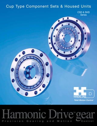
  • 1. Cup Type Component Sets & Housed Units CSD & SHD Series Total Motion Control Harmonic Drive™gear P r e c i s i o n G e a r i n g a n d M o t i o n C o n t r o l
  • 2. Sold & Serviced By: ­­­­­­­­­­­2 SHD Series ELECTROMATE Toll Free Phone (877) SERVO98 Toll Free Fax (877) SERV099 www.electromate.com sales@electromate.com
  • 3. SHD Series Harmonic Drive™ Gear Contents ­­­­­­­­­­­3 ­­­­­­­­­­­2 ABOUT HARMONIC DRIVE CSD & SHD Ordering Information 4 Harmonic Drive Gearing Mechanism Principle & Structure 5 Driving Configurations 6 Application Examples 7 CSD Rating Table 8 SHD Rating Table 9 Technical Terms, Strength & Life 10 Technical Terms, Life & Torque 11 Selection Procedure & example 12 COMPONENT TYPE CSD CSD External Dimension & Shape 14 Lubrication 16 Recommended Tolerances for Assembly 19 Wave Generator Assembly Notes for CSD 20 Assembly of the Flexspline 21 Assembly of the Circular Spline, Assembly Notes 22 CSD Assembly Procedure 23 HOUSED UNIT TYPE SHD SHD External Dimensions of Housed Unit 24 Specifications for Cross Roller Bearing 26 Output Bearing Calculations 27 Output Bearing Life 28 Lubrication 29 Recommended Tolerances for Assembly 30 SHD Assembly Notes and Procedure 35 ENGINEERING DATA CSD & SHD Efficiency of Component Set 36 Efficiency of Housed Unit 37 No Load Running Torque 38 Starting Torque and Backdriving Torque 40 Positioning Accuracy 41 Torsional Stiffness 41 Hysteresis Loss 43 Harmonic Drive LLC 800-921-3332 Sold & Serviced By: ELECTROMATE Toll Free Phone (877) SERVO98 Toll Free Fax (877) SERV099 www.electromate.com sales@electromate.com
  • 4. Sold & Serviced By: ­­­­­­­­­­­4 SHD Series 4 S Series CSF Series CSD & SHD Series Ordering Code Ordering Information CSD Name of Model Size Ratio Model 14 50, 100 17 50, 100 20 50, 100, 160 2A-GR: Component Type None: Standard CSD 25 50, 100, 160 (size 14 and 17 32 50, 100, 160 are 2A-R) 40 50, 100, 160 BB: Big Bore 50 50, 100, 160 on Flexspline 14 50, 100 (CSD Series) 17 50, 100 SHD 20 50, 100, 160 2SH 25 50, 100, 160 Simplicity Unit Type SP: Special 32 50, 100, 160 40 50, 100, 160 Evolution of Harmonic Drive™ Gear Revolution Harmonic Drive™ precision gear continues to evolve by improving performance and functionality. By pursuing strength and The CSF achieved a stiffness, a new tooth profile reduction in axial length was invented. The “S” tooth of approximately 50% Achieve another axial doubled torque, life and stiffness length reduction of approximately 50% ELECTROMATE Toll Free Phone (877) SERVO98 Toll Free Fax (877) SERV099 www.electromate.com sales@electromate.com
  • 5. About Harmonic DSriHveD™ S Gereiaers Principle and Structure Sold & Serviced By: ELECTROMATE Toll Free Phone (877) SERVO98 Toll Free Fax (877) SERV099 5 ­­­­­­­­­­­5 Outer Cross Roller Bearing (Output) 0 º SHD CSD Circular Spline Wave Generator Flexspline Wave Generator www.electromate.com sales@electromate.com 90º 360º The Flexspline is elliptically shaped by The Wave Generator and engaged with the Circular Spline at the major elliptical axis. The teeth completely disengage on the minor axis. For each 360 degrees clockwise movement of the Wave Generator, the Flexspline moves counterclockwise by two teeth relative to the Circular Spline. When the Circular Spline is fixed and the Wave Generator rotates clockwise, the Flexspline is elastically deformed and rotates counterclockwise relative to the Circular Spline. Circular Spline Wave Generator Cross Roller Bearing Flexspline Bolt (temporary) Flexspline Circular Spline Circular Spline Flexspline Wave Generator System Components The FLEXSPLINE is a non-rigid, steel cylindrical cup with external teeth on a slightly smaller pitch diameter than the Circular Spline. It fits over and is held in an elliptical shape by the Wave Generator. The WAVE GENERATOR is a thin raced ball bearing fitted onto an elliptical plug serving as a high efficiency torque converter. The CIRCULAR SPLINE is a rigid ring with internal teeth, engaging the teeth of the Flexspline across the major axis of the Wave Generator.
  • 6. Driving Configurations A variety of different driving configurations are possible, as shown below. The reduction ratio R, given in the tables on page 7 and 8 correspond to arrangement 1, in which the Wave Generator acts as the input element, the Circular Spline is fixed and the Flexspline acts as the output element. ­­­­­­­­­­­6 About Harmonic DSriHveD™ S Gereiaers Driving Configurations 6 Ratio = input speed output speed 3. Reduction Gearing WG Fixed FS Input CS Output R + 1 Ratio = R [Equation 3] Input and output in same direction. 6. Speed Increaser Gearing FS Fixed CS Input WG Output 1 Ratio = R + 1 [Equation 6] Input and output in same direction. 1. Reduction Gearing CS Fixed WG Input FS Output Ratio = — R 1 [Equation 1] Input and output in opposite direction. 4. Speed Increaser Gearing WG Fixed CS Input FS Output R Ratio = R + 1 [Equation 4] Input and output in same direction. 7. Differential Gearing WG Control Input CS Main Drive-Input FS Main Drive-Output Numerous differential functions can be obtained by combinations of the speed and rotational direction of the three basic elements. 2. Reduction Gearing FS Fixed WG Input CS Output R + 1 Ratio = 1 [Equation 2] Input and output in same direction. 5. Speed Increaser Gearing CS Fixed FS Input WG Output Ratio = — 1 R [Equation 5] Input and output in opposite direction. Sold & Serviced By: ELECTROMATE Toll Free Phone (877) SERVO98 Toll Free Fax (877) SERV099 www.electromate.com sales@electromate.com
  • 7. Application Examples About Harmonic DSriHveD™ S Gereiaers Wave Generator ­­­­­­­­­­­7 Flexspline Circular Spline Simplicity Unit Circular Spline Flexspline Output 1 Output 2 Wave Generator Flexspline (SHD) CSD Series Rotary Table for Machine Tool SHD Series SCARA CSD • SHD Series 2 Axis - Output Unit Harmonic Drive LLC 800-921-3332 7 Sold & Serviced By: ELECTROMATE Toll Free Phone (877) SERVO98 Toll Free Fax (877) SERV099 www.electromate.com sales@electromate.com
  • 8. Sold & Serviced By: ­­­­­­­­­­­8 SHD Series 8 Table 1 CSD Gear Rated Limit for Limit for Limit for Maximum Limit for Moment Size Ratio Torque Repeated Average Momentary Input Average of at Peak Torque Peak Speed Input Inertia R 2000 Torque Torque Speed Tr rpm Nm Nm Nm rpm rpm I J Nm in-lb Nm in-lb Nm in-lb Nm in-lb Oil Grease Oil Grease x10-4kg•m2 x10-5kgf•m•s2 14 50 3.7 33 12 106 4.8 42 24 212 14000 8500 6500 3500 0.021 0.021 100 5.4 48 19 168 7.7 68 31 274 17 50 11 97 23 204 18 159 48 425 10000 7300 6500 3500 0.054 0.055 100 16 142 37 327 27 239 55 487 50 17 150 39 345 24 212 69 611 20 100 28 248 57 504 34 301 76* 673* 10000 6500 6500 3500 0.090 0.092 (65) (575) 160 28 248 64 566 34 301 76* 673* (65) (575) 50 27 239 69 611 38 336 127 1124 (135) (1195) 25 100 47 416 110 974 75 664 152* 1345* 7500 5600 5600 3500 0.282 0.288 (135) (1195) 160 47 416 123 1089 75 664 152* 1345* 50 53 469 151 1336 75 664 268 2372 (331) (2929) 32 100 96 850 233 2062 151 1336 359* 3177* 7000 4800 4600 3500 1.09 1.11 (331) (2929) 160 96 850 261 2310 151 1336 359* 3177* 50 96 850 281 2487 137 1212 480 4248 (580) (5133) 40 100 185 1637 398 3522 260 2301 694* 6142* 5600 4000 3600 3000 2.85 2.91 (580) (5133) 160 206 1823 453 4009 316 2797 694* 6142* 50 172 1522 500 4425 247 2186 1000 8850 (1315) (11638) 50 100 329 2912 686 6071 466 4124 1440 12744 4500 3500 3000 2500 8.61 8.78 (1315) (11638) 160 370 3275 823 7284 590 5222 1577* 13956* Note: The moment of inertia : I=1/4GD2, measured at the input The momentary peak torque is limited by tightening torque on the flexspline. The values in parenthesis are values in the case of the Big Bore option on the flexspline. About Harmonic Drive™ Gear CSD Rating Table ELECTROMATE Toll Free Phone (877) SERVO98 Toll Free Fax (877) SERV099 www.electromate.com sales@electromate.com
  • 9. About Harmonic DSriHveD™ S Gereiaers SHD Rating Table Table 2 ­­­­­­­­­­­9 SHD Ratio Rated Limit for Limit for Limit for Maximum Limit for Moment Size Torque Repeated Average Momentary Input Average of R at Peak Torque Peak Speed Input Inertia 2000 Torque Torque Speed Tr rpm Nm Nm Nm rpm rpm I J Nm in-lb Nm in-lb Nm in-lb Nm in-lb Grease Grease x10-4kg•m2 x10-5kgf•m•s2 14 50 3.7 33 12 106 4.8 42 23 204 8500 3500 0.021 0.021 100 5.4 48 19 168 7.7 68 35 310 17 50 11 97 23 204 18 159 48 425 7300 3500 0.054 0.055 100 16 142 37 327 27 239 71 628 50 17 150 39 345 24 212 69 611 20 100 28 248 57 504 34 301 95 841 6500 3500 0.090 0.092 160 28 248 64 566 34 301 95 841 50 27 239 69 611 38 336 127 1124 25 100 47 416 110 974 75 664 184 1628 5600 3500 0.282 0.288 160 47 416 123 1089 75 664 204 1805 50 53 469 151 1336 75 664 268 2372 32 100 96 850 233 2062 151 1336 420 3717 4800 3500 1.09 1.11 160 96 850 261 2310 151 1336 445 3938 50 96 850 281 2487 137 1212 480 4248 40 100 185 1637 398 3522 260 2301 700 6195 4000 3000 2.85 2.91 160 206 1823 453 4009 316 2797 765 6770 Note: The moment of inertia : I=1/4GD2, measured at the input. Harmonic Drive LLC 800-921-3332 9 Sold & Serviced By: ELECTROMATE Toll Free Phone (877) SERVO98 Toll Free Fax (877) SERV099 www.electromate.com sales@electromate.com
  • 10. About Harmonic DSriHveD™ S Gereiaers Technical Terms Strength & Life Definition of Ratings Rated Torque (Tr) Rated torque indicates allowable continuous load torque at 2000 rpm input speed. Limit for Repeated Peak Torque (refer to figure 1) During acceleration a deceleration the Harmonic Drive™ gear experi-ences Sold & Serviced By: ­­­­­­­­­­­10 10 a peak torque as a result of the moment of inertia of the output load. The table indicates the limit for repeated peak torque. Limit for Average Torque In cases where load torque and input speed vary, it is necessary to calculate an average value of load torque. The table indicates the limit for average torque. The average torque calculated must not exceed this limit. Limit for Momentary Peak Torque (refer to figure 1) The gear may be subjected to momentary peak torques in the event of a collision or emergency stop. The magnitude and frequency of occurrence of such peak torques must be kept to a minimum and they should, under no circumstance, occur during normal operating cycle. The allowable number of occurrences of the momentary peak torque may be calculated by using equation 1. Also see section “strength and life”. Figure 1 S t a r t Routine Stop Abnormal Impact To rque Maximum Input Speed, Limit for average input speed Do not exceed the allowable rating. Moment of Inertia The rating indicates the moment of inertia reflected to the wave generator (gear input). Strength and Life The non-rigid Flexspline is subjected to repeated deflections, and its strength determines the torque capacity of the Harmonic Drive™ gear. The values given for Rated Torque at Rated Speed and for the allo-wable Repeated Peak Torque are based on an infinite fatigue life for the Flexspline. The torque that occurs during a collision must be below the momenta-ry peak torque (impact torque). The maximum number of occurrences is given by the equation below. [Equation 1] 1.0 X 10⁴ n: Input speed before collision N = ____________ 2 X n 60 X t t: Time interval during collision Please note: If this number is exceeded, the Flexspline may experience a fatigue failure. Ratcheting phenomenon When excessive torque is applied while the gear is in motion, the teeth between the Circular Spline and Flexspline may not engage pro-perly. This phenomenon is called ratcheting and the torque at which this occurs is called ratcheting torque. Ratcheting may cause the Flexspline to become non-concentric with the Circular Spline. (See figure 1 & 2 on page 12) Operating in this condition may result in shortened life and a Flexspline fatigue failure. Figure 2 Circular Spline Flexspline This condition is called “dedoidal”. Note! When ratcheting occurs, the teeth mesh abnormally as shown above. Vibration and Flexspline damage may occur. Once ratcheting occurs, the teeth wear excessively and the ratcheting torque may be lowered. Speed Cycle S t a r t T ime T ime Load To rque Load To rque Repeated Peak To rque Momentary Peak To rque Number of Rotations of Wave Generator ELECTROMATE Toll Free Phone (877) SERVO98 Toll Free Fax (877) SERV099 www.electromate.com sales@electromate.com
  • 11. Life Technical Terms ­­­­­­­­­­­11 SHD Series Table 6 Buckling Torque Nm SHD Size All Ratio 14 130 17 260 20 470 25 850 32 1800 40 3600 Repeated Peak Torque Harmonic Drive LLC 800-921-3332 The Life of a Wave Generator The normal life of a gear is determined by the life of the wave generator bearing. The life may be calculated by using the input speed and the output load torque. Rated Lifetime Ln : (n = 10 or 50) , hours L10 CSD,SHD: 7,000 L50 CSD,SHD: 35,000 Equation for the expected life of the wave generator under normal operating conditions is given by the equation below. [Equation 2] Lh = Ln • ( Tr )3 • ( Nr ) Tav Nav Lh : Expected Life, hours Ln : Rated Lifetime at L10 or L50 , hours Tr : Rated Torque (Tables 1, 2, 3) Nr : Rated input speed (2000 rpm) Tav : Average load torque on output side (page 14) Nav : Average input speed (page 14 Relative Torque Rating The chart below shows the various torque specifications relative to rated torque. Rated Torque has been normalized to 1 for comparison. Figure 3 17 16 10 9 8 7 6 5 4 3 2 1 105 0 Buckling Torque Racheting Torque Fatique Strength of Flexspline Life of the Wave Generator(L10) 106 107 108 109 1010 Total Number of Input Rotations Load Torque (Rated Torque = 1) Rated Torque NON-OPERATING ZONE NORMAL OPERATING ZONE Momentary Peak Torque SHD Ratcheting Torque Table 5 Nm Size Ratio 50 100 160 14 88 84 – 17 150 160 – 20 220 260 220 25 450 500 450 32 980 1000 980 40 1800 2100 1800 Table 4 Buckling Torque Nm CSD Size All Ratio 14 190 17 330 20 560 25 1000 32 2200 40 4300 50 8000 CSD Ratcheting Torque Table 3 Nm Size Ratio 50 100 160 14 88 84 – 17 150 160 – 20 220 260 220 25 450 500 450 32 980 1000 980 40 1800 2100 1800 50 3700 4100 3600 11 About Harmonic Drive™ Gear Sold & Serviced By: ELECTROMATE Toll Free Phone (877) SERVO98 Toll Free Fax (877) SERV099 www.electromate.com sales@electromate.com
  • 12. SHD Series Sold & Serviced By: ­­­­­­­­­­­12 12 Torque rpm t1 T1 T2 T3 T4 Tn t2 t3 t4 tn n1 n3 n4 nn n2 Time n1 n2 nn are an average value. Time NG OK OK OK OK OK NG NG NG NG Size Selection Generally, the operating conditions consist of fluctuating torques and output speeds. Also, an unexpected impact output torque must be considered. The proper size can be determined by converting fluctuating load torque into average load torque and equivalent load torque. This procedure involves selecting the size based on load torque for com-ponent sets. This procedure does not consider the life of the output bearing for housed units. Determining the life of the output bearing for various axial, radial, and moment loads is outlined on page 25. Figure 4 Parameters Load Torque Tn (Nm) Time tn (sec) Output Speed nn (rpm) Normal Operating Pattern Acceleration T1,t1, n1 Regular Operation T2,t2, n2 Deceleration T3,t3, n3 Dwell T4,t4, n4 Maximum RPM Max output speed no maximum Max input speed ni maximum Impact Torque Ts,ts, ns Ratings Rated Torque Tr Rated Speed nr =2000 rpm Flow Chart for selecting a size Please use the flowchart shown below for selecting a size. Operating conditions must not exceed the performance ratings as described on page 12. Calculation of the average output torque Tav = 3 n1•t1•|T1| 3+n2•t2•|T2| 3+... nn•tn•|Tn| 3 n1•t1+n2•t2+... nn tn Selection of tentative size under the condition shown below. Average Output Speed no av = n1•t1•n2•t2+... nntn t1+t2•t2+...tn Determine Gear Ratio ni max <= R no max ni max may be limited by the motor. Calculation of the average input speed ni av = no av •R Calculation of maximum input speed ni max = no max •R ni av <= Limit for average speed ni max <= Limit for maximum speed Confirm if T1 and T3 are less than the repeated peak torque specification. Confirm if Ts (impact torque) is less than the momentary peak torque specification. Calculate the allowable number of rotations during impact torque. Ns = 104 ••••••Ns <= 1.0X10⁴ 2• ns•R •ts 60 Calculate wave generator life. Lh = Ln • ( Tr )3 •( nr ) Tav ni av Make sure that the calculated life is suitable for the application. Gear is suitable for torque and speed requirements Also consider output bearing, environment, etc. Consider a different size or change operating requirements About Harmonic Drive™ Gear Selection Procedure ELECTROMATE Toll Free Phone (877) SERVO98 Toll Free Fax (877) SERV099 www.electromate.com sales@electromate.com
  • 13. Selection Example ­­­­­­­­­­­13 About Harmonic DSriHveD™ S Gereiaers Values of an each Load Torque Pattern Load Torque Tn (Nm) no max = 14 rpm Time tn (sec) ni max = 1800 rpm Output Speed nn (rpm) Normal Operating Pattern Acceleration T1 = 400 Nm, t1 = 0.3 sec, n1 = 7 rpm Ts = 500 Nm, ts = 0.15 sec, ns = 14 rpm Regular Operation Stop T2 = 320 Nm, t2 = 3 sec, n2 = 14 rpm Deceleration T3 = 200 Nm, t3 = 0.4 sec, n3 = 7 rpm L10 > 7000 hrs. Dwell T4 = 0 Nm, t4 = 0.2 sec, n4 = 0 rpm Oil Lubrication OK OK OK OK OK NG NG NG NG NG Tav (Nm) Tav = 3 7rpm•0.3sec•| 400Nm| 3+14rpm•3sec•|320Nm| 3+7rpm•0.4sec•|200Nm| 3 7rpm•0.3sec+14rpm•3sec+7rpm•0.4sec Tav = 319Nm<466Nm (for CSD-50-100-2A-GR) no av (rpm) 7rpm•0.3sec+14rpm•3sec+7rpm•0.4sec = 12 rpm •0.3sec+3sec+0.4sec+0.2sec (R) 1800 RPM = 128.6>100 14 rpm ni av = 12rpm•100=1200rpm no max ni max (rpm) ni max = 14rpm•100=1400rpm ni av =1440rpm<3600rpm (for CSD-50-100-2A-GR) ni max =1680rpm<5600rpm (for CSD-50-100-2A-GR) Confirm that T1 and T3 are within a T1, T3 (Nm) T1 = 400Nm<686Nm (for CSD-50-100-2A-GR) T3 = 200Nm<686Nm (for CSD-50-100-2A-GR) TS (Nm) TS ) = 500Nm<1440Nm (for CSD-50-100-2A-GR) NS Calculate an allowable number of rotation(Ns) and confirm <= 1.0 x 10⁴ NS = 104 NS =1429<1.0 x 10⁴ 2 • 14rpm•100 • 0.15 60 Calculate a life time. L10 = 7000 (329Nm)3 (2000rpm) 1319Nm • 1440rpm L10 = 10665 > 7000 (LB10) CSD-50-100-2A-GR Consider a different size or change operating requirements Harmonic Drive LLC 800-921-3332 13 Sold & Serviced By: ELECTROMATE Toll Free Phone (877) SERVO98 Toll Free Fax (877) SERV099 www.electromate.com sales@electromate.com
  • 14. SHD Series Sold & Serviced By: ­­­­­­­­­­­14 14 *2 1 2 3 1 2 1 3 C0.4 G 1 Ball Separator 2 Wave Generator Bearing 3 Wave Generator Plug Size: 14, 17 Size: 20, 25, 32, 40, 50 Size: 14, 17 Size: 20, 25, 32, 40, 50 U-øV øZ3 øT G1 Expanded G Section L-øM 2-N øZ1 15º øZ2 4-S øQ øR C D F E O b c 4 øAh7 C0.5 C0.5 C0.3 1 1 3 øa øP øBH7 øK H6 øJ øa H A 1. #14 and 17 are co.4. 2. #40 and 50 are co.5. 3. #14 is 30º, #17 is 22.5º. 4. #14 ‑32 are co.3, #40 and #50 are co.5. *1 **4 Outside appearance varies depending on size. CSD Series CSD External Dimension & Shape ELECTROMATE Toll Free Phone (877) SERVO98 Toll Free Fax (877) SERV099 www.electromate.com sales@electromate.com
  • 15. CSD External Dimension & Shape ­­­­­­­­­­­15 SCHSD Seerriieess CSD Dimensions Table 7 unit: (mm) Size 14 17 20 25 32 40 50 øA h7 50 0 -0.025 60 0 -0.030 70 0 -0.030 85 0 -0.035 110 0 -0.035 135 0 -0.040 170 0 -0.040 øBH7 11+0.018 0 15+0.018 0 20+0.021 0 24+0.021 0 32+0.025 0 40+0.025 0 50+0.025 0 C 11 12.5 14 17 22 27 33 D 6.5+0.2 0 7.5+0.2 0 8 +0.3 0 10+0.3 0 13+0.3 0 16+0.3 0 19.5+0.3 0 E 1.4 1.7 2 2 2.5 3 3.5 F 4.5 5 6 7 9 11 13.5 G1 0.3 0.3 0.3 0.4 0.5 0.6 0.8 H 4 5 5.2 6.3 8.6 10.3 12.7 øJ 23 27.2 32 40 52 64 80 øK H6 11+0.011 0 11+0.011 0 16+0.011 0 20+0.013 0 30+0.013 0 32+0.016 0 44+0.016 0 L 6 8 12 12 12 12 12 øM 3.4 3.4 3.4 3.4 4.5 5.5 6.6 N M3 M3 M3 M3 M4 M5 M6 O _ _ 3.3 3.3 4.4 5.4 6.5 øP _ _ 6.5 6.5 8 9.5 11 øQ 44 54 62 75 100 120 150 øR 17 21 26 30 40 50 60 S M3 M3 M3 M3 M4 M5 M6 øT 17 19.5 24 30 41 48 62 U 9 8 9 9 11 10 11 øV 3.4 4.5 4.5 5.5 6.6 9 11 øZ0.2 0.2 0.2 0.2 0.25 0.25 0.3 1 øZ0.25 0.25 0.2 0.2 0.25 0.25 0.3 2 øZ0.2 0.25 0.25 0.25 0.3 0.5 0.5 3 øa 38 45 53 66 86 106 133 b 6.5 7.5 8 10 13 16 19.5 c 1 1 1.5 1.5 2 2.5 3.5 Minimum housing clearance weight (kg) 0.06 0.10 0.13 0.24 0.51 0.92 1.9 Weight Note: Standard dimension for size 14 and 17 is the maximum bore. Dimensions for BB Table 8 unit:mm Size 20 25 32 40 50 ø KH6 20+0.013 0 24+0.013 0 32+0.016 0 40+0.016 0 50+0.016 0 U 12 12 12 14 14 ø V 3.4 4.5 5.5 6.6 9 ø T 26 32 42 52 65 ø Z3 0.2 0.25 0.25 0.3 0.5 • Installed surface on Circular Spline is shown as A. Use this surface for installation in case. • Dimensions shown below may be modified as a special order. B: Dimension of Wave generator U and V: Dimension of Flexspline L and M: Dimension of Circular spline • Dimensions for C•D•G must meet the tolerance values shown above. • øa, b, c must exceed the values shown above due to deformation of the flexspline. Harmonic Drive LLC 800-921-3332 15 Note: Standard dimension for size 14 and 17 is the maximum bore. Sold & Serviced By: ELECTROMATE Toll Free Phone (877) SERVO98 Toll Free Fax (877) SERV099 www.electromate.com sales@electromate.com
  • 16. SHD Series Lubricant Grease lubricant is the standard for the CSD unit. The temperature range is shown below. (Exceptions are shown on page 17.) Lubricant Grease SK-1A 0ºC~+40ºC Grease SK-2 0ºC~+40ºC Grease 4B-No.2 -10ºC~+70ºC Oil ISO VG68 0ºC~+40ºC Lubricant Grease Harmonic Grease SK-1A Grease Harmonic Grease SK-2 Grease Harmonic Grease 4B-No.2 Oil Industrial gear oil #2(high pressure) ISO VG68 Harmonic Grease SK-1A This grease is developed for a Harmonic Drive™ gear and features good durability and efficiency. Harmonic Grease SK-2 This grease is developed for a small size Harmonic Drive™ gear and features smooth rotation of the Wave Generator since high pressure additive is liquefied. Harmonic Grease 4BNo.2 This grease is developed for Harmonic Drive™ gear and features long life and a wide range of temperature. Note 1 Grease lubrication must have proper sealing, this is essential for 4B No.2. Rotating part: Oil seal with spring is needed. Mating part: O ring or seal adhesive is needed. Note 2 The grease has the highest deterioration rate in the region where the grease is subjected to the greatest shear (near wave generator). Its viscosity is between JIS No.0 and No.00 depending on the operation. Recommended Grease Size 14 17 20 25 32 40 50 SK-1A — — O O O O O SK-2 O O Δ Δ Δ Δ — 4BNo.2 • • • • • • • •: recommended grease for long life and high load O: Standard Δ: Semistandard Characteristics of Grease Grease SK-1A SK-2 4BNo.2 Durability O O • Fretting Resistance O O • Low Temp Δ Δ • Grease Leakage • • Δ •: Excellent O: Good Δ: Exercise Caution Recommended Grease ­­­­­­­­­­­16 16 Grease SK-1A SK-2 4B No.2 Base Oil Refined mineral hydrocarbon Refined mineral hydrocarbon Hydrocarbon type synthetic base oil base oil oil and polymer Thickening Agent Lithium soap Lithium soap Urea thickener thickener Additive Organic molybdenum, etc. Organic molybdenum, etc. Organic molybdenum, etc.s NLGI Consistency No. No.2 No.2 No.1.5 Viscosity (25C) cSt 265 to 295 265 to 295 290 to 320 Melting Point 197ºC 198ºC 247ºC Color Yellow Green Light Yellow Life 5 Years in Airtight Container CSD Series Lubrication Sold & Serviced By: ELECTROMATE Toll Free Phone (877) SERVO98 Toll Free Fax (877) SERV099 www.electromate.com sales@electromate.com
  • 17. Lubrication Recommended Dimensions for Inner Case Recommended dimensions for inner case must meet with numbers shown below. These dimensions must be maintained to pre-vent damage to the gear and to maintain a proper grease cavity. Figure 4 Recommended Dimensions for Inner Case Table 9 Unit: mm ­­­­­­­­­­­17 SHD Series Size 14 17 20 25 32 40 50 ø a 38 45 53 66 86 106 133 b 6.5 7.5 8 10 13 16 19.5 c 1(3) 1(3) 1.5(4.5) 1.5(4.5) 2(6) 2.5(7.5) 3.5 ød +0.5 0 16 26 30 37 37 45 45 CIRCULAR SPLINE FLEXSPLINE WAVE GENERATOR Harmonic Drive LLC 800-921-3332 Note: Values in parenthesis show the value when the Wave Generator is pointing up. Apply thin coat to avoid corrosion Fill the toothbed with grease Fill the toothbed with grease Apply grease to inner surface in accordance with a value shown above. Apply thin coating of grease before installation Fill cavity between retainer and bearing with grease. Figure 5 Grease Usage Table 10 Unit: g Size 14 17 20 25 32 40 50 amount 3.5 5.2 9.0 17 37 68 131 17 CSD Sold & Serviced By: ELECTROMATE Toll Free Phone (877) SERVO98 Toll Free Fax (877) SERV099 www.electromate.com sales@electromate.com
  • 18. SHD Series Lubrication Oil Temperature In normal use, the oil temperature must not exceed 90ºC, Above this temperature oil quickly loses its lubricating capabilities. Other notes: Avoid mixing different kinds of oil. The gear should be in an individual case when installed. High Temperature Lubricants Standard temperature is the grease temperature during operation. It is not the ambient temperature. Sold & Serviced By: ­­­­­­­­­­­18 1010 10 9 10 8 10 7 Graph of LGTn vs. Temperature 4B No.2 SK-1A SK-2 Grease Life Wave Generator Life 20 40 60 80 100 120 Grease Temperature (ºC) LGT n, Total Number of Rotations of Wave Generator Oil Change The first oil change should be performed after 100 hours of operation. The need to perform subsequent oil changes will depend on operating conditions, but should take place at intervals of approximately 1000 running hours. The temperature range of the grease can be extended as indicated in the possible temperature range shown. At the low end of this range the efficiency will be low due to an increase in viscosity of the lubri-cant. At the high end of this range the lubricant life will be low due to an increased deterioration rate from the high temperature. Harmonic Grease 4B No.2 Type of lubricant Standard temperature range Possible temperature range grease –10ºC~+110ºC –50ºC~+130ºC High Temperature Lubricant Type of lubricant Name of lubricant and manufacturer Possible temperature range grease Mobil Grease 28 –5ºC~+160ºC oil Mobil SHC-626 –5ºC~+140ºC Low Temperature Lubricant Type of lubricant Name of lubricant and manufacturer Possible temperature range Grease Multemp SH-K2 Kyodo Yushi –30ºC~+50ºC Iso Flex LDS-18 special A NOK kluber –25ºC~+80ºC Oil SH-200-100CS Tore Silicon –10ºC~+110ºC Shintesso D-32EP NOK kluber –25ºC~+90ºC Grease Change The wear characteristics of the gear is strongly influenced by the condition of the grease lubrication. The condition of the grease is affected by the ambient temperature. The graph shows the maximum number of input rotations for various temperatures. This graph applies to applications where the average load torque does not exceed the rated torque. In cases where the average load torque exceeds rated torque, calcu-late the grease change interval using the equation shown below. Equation where average load torque exceeds rated torque [Equation [3] LGT = LGTn X ( Tr )3 Tav Symbol of Equation [2] LGT Grease change (average torque is over rated torque), input rotations LGTn Grease change (average torque is below rated torque), input rotations (From Graph) Tr Rated Torque Tav Average load torque on output Figure 6 18 CSD Series ELECTROMATE Toll Free Phone (877) SERVO98 Toll Free Fax (877) SERV099 www.electromate.com sales@electromate.com
  • 19. Tolerance Assembly Notes ­­­­­­­­­­­19 SCHSD Seerriieess d A a A e B f B A B Recommended Tolerance H7 Recommended øc A øg B Shaft Tolerance h6 b A Casefit Surface Circular Spline Installation Surface Casefit Surface Wave Generator Installation Surface Recommended Tolerance H7 Flexspline Installation Surface Recommended Shaft Tolerance h6 Recommended Tolerances for Assembly Tolerance for Assembly Table 11 unit:mm Size 14 17 20 25 32 40 50 a 0.011 0.012 0.013 0.014 0.016 0.016 0.018 b 0.008 0.011 0.014 0.018 0.022 0.025 0.030 ø c 0.015 0.018 0.019 0.022 0.022 0.024 0.030 d 0.011 0.015 0.017 0.024 0.026 0.026 0.028 e 0.011 0.015 0.017 0.024 0.026 0.026 0.028 f 0.008 0.010 0.010 0.012 0.012 0.012 0.015 ø g 0.016 0.018 0.019 0.022 0.022 0.024 0.030 Sealing structure A seal structure is needed to maintain the high durability of the gear and prevent grease leakage. Key Points to Verify • Rotating parts should have an oil seal (with spring), surface should be smooth (no scratches) • Mating flanges should have an O Ring, seal adhesive • Screws should have a thread lock (Loctite 242 recommended) or seal adhesive. Note: If you use Harmonic Grease 4BNo.2, strict sealing is required. Harmonic Drive LLC 800-921-3332 19 Sold & Serviced By: ELECTROMATE Toll Free Phone (877) SERVO98 Toll Free Fax (877) SERV099 www.electromate.com sales@electromate.com
  • 20. SCHSDD SSeerriieess Wave Generator Assembly Notes for CSD Sold & Serviced By: ­­­­­­­­­­­20 20 F F Axial Force of Wave Generator When a CSD gear is used to accelerate a load, the deflection of the Flexspline leads to an axial force acting on the Wave Generator. This axial force, which acts in the direction of the closed end of the Flexspline, must be supported by the bearings of the input shaft (motor shaft). When a CSD gear is used to decelerate a load, an axial force acts to push the Wave Generator out of the Flexspline cup. Maximum axial force of the Wave Generator can be calculated by the equation shown below. The axial force may vary depending on its operating condition. The value of axial force tends to be a larger number when using high torque, extreme low speed and constant operation. The force is calculated (approximately) by the equation. In all cases, the Wave Generator must be axially (in both direc-tions), as well as torsionally, fixed to the input shaft. Note: Please contact us for further information on attaching the Wave Generator to the input (motor) shaft. Direction for Thrust Force of Wave Generator direction for thrust force in acceleration Figure 7 direction for thrust force in deceleration Calculation Example size : 32 Ratio : i=1/50 Output Torque : 200Nm F=2x 200 x 0.07xtan 30º+16 (32x0.00254) F=215N Equation [4] for axial force Gear Ratio equation i=1/50 F=2x T x 0.07 x tan 30º+2μPF D i=1/100 and up F=2x T x 0.07 x tan 20º+2μPF D Symbols for equation [4] F thrust force N D Gear Size x 0.00254 m T output torque Nm 2μPF thrust force by bearing Nm (see table) Table 12 Thrust Force by Bearing Size 2μPF (Nm) 14 2.1 17 4.1 CSD 20 5.6 25 9.8 32 16 40 24 50 39 CSD ELECTROMATE Toll Free Phone (877) SERVO98 Toll Free Fax (877) SERV099 www.electromate.com sales@electromate.com
  • 21. Flexspline Assembly Holes and Bolts ­­­­­­­­­­­21 SHD Series Sold & Serviced By: Harmonic Drive LLC 800-921-3332 21 CSD Diaphragm Head of bolt, nut and washer should not exceed the diameter of J Figure 8 Avoid Boss diameter of Flexspline Table 13 Size 14 17 20 25 32 40 50 øJ 23 27.2 32 40 52 64 80 Number of Holes and Location (Standard) Number of Holes: 8 Number of Holes: 9 Number of Holes: 10 Number of Holes: 11 CSD-17 CSD-14, 20, 25 CSD-40 CSD-32, 50 Number of Holes and Location (Big Bore Option) Number of Holes: 12 Number of Holes: 14 CSD-20.25 CSD-32, 40, 50 Flexspline Bolts Table 14 Standard Big Bore Option Size 14 17 20 25 32 40 50 BB 20 BB 25 BB 32 BB 40 BB 50 Number of Bolts 9 8 9 9 11 10 11 12 12 14 14 14 Size M3 M4 M4 M5 M6 M8 M10 M3 M4 M5 M6 M8 Pitch Circle Diameter mm 17 19.5 24 30 41 48 62 26 32 42 52 65 Clamp N•m 2.0 4.5 4.5 9.0 15.3 37 74 2 4.5 9.0 15.3 37 Torque Torque N•m 32 55 76 152 359 694 1577 65 135 331 580 1315 transmission Note: 1. The material of the thread must withstand the clamp torque. 2. Recommended bolt : JIS B 1176 socket head cap screw strength range : JIS B 1051 over 12.9 3. Torque coefficient : K=0.2 4. Clamp coefficient A=1.4 5. Friction coefficient on the surface contacted: 0.15 6. Momentary peak torque is limited in Big Bore since bolt torque transmission of Big Bore is smaller than standard. ELECTROMATE Toll Free Phone (877) SERVO98 Toll Free Fax (877) SERV099 www.electromate.com sales@electromate.com
  • 22. SCHSDD SSeerriieess Circular Spline Assembly Installation Circular Spline Bolt Installation Table 15 Sold & Serviced By: ­­­­­­­­­­­22 22 Size Standard 14 17 20 25 32 40 50 Number of Bolts 6 8 12 12 12 12 12 Size M3 M3 M3 M3 M4 M5 M6 Pitch Circle Diameter mm 44 54 62 75 100 120 150 Clamp Torque Nm 2.0 2.0 2.0 2.0 4.5 9.0 15.3 Torque transmission Nm 55 90 155 188 422 810 1434 Note: flexspline circular spline wave generator When flexspline and wave generator are assembled, open part of flexspline will expand at major axis. 1. The material of the thread must withstand the clamp torque. 2. Recommended bolt: JIS B 1176 socket head cap screw strength range : JIS B 1051 over 12.9. 3. Torque coefficient : K=0.2 4. Clamp coefficient A=1.4 5. Friction coefficient on the surface contacted : 0.15 Component Assembly Procedure Please see the following notes. ELECTROMATE Toll Free Phone (877) SERVO98 Toll Free Fax (877) SERV099 www.electromate.com sales@electromate.com
  • 23. CSD Assembly Procedure ­­­­­­­­­­­23 SCHSD Seerriieess Harmonic Drive LLC 800-921-3332 23 CSD assembly procedure Note for assembly structure for CSD Wave Generator 1. Avoid overloading the Wave Generator bearing during installation, rotate the Wave Generator as you easily install. 2. Since the Wave Generator of the CSD does not have an Oldham coupling, make sure that the position is within the recommended tolerance shown on page18. 3. Installation bolts on Wave Generator and installation bolt on Flexspline should not interfere each other. Circular Spline 1. Be sure flatness and skewness are minimized. 2. Make sure there are no burrs or foreign substances. 3. Make sure there is enough room to have the minimum clearance in the housing. 4. Make sure that the Circular Spline can rotate in the housing when it is installed 5. When a bolt is inserted into a bolt hole, make sure that the bolt hole is located properly. 7. Bolts should not be tightened at the same time. Apply half of the recommended torque to tighten bolts, and then tighten bolts at the recommended torque. The order of tightening bolts should be done diagonally. Avoid using pins to secure the Circular Spline if possible. Flexspline 1. Be sure flatness and skewness are minimized. 2. Make sure there are no burrs or foreign substances. 3. Make sure there is enough room to have the minimum clearance in the housing. 4. When a bolt is inserted into a bolt hole, make sure that the bolt hole is located properly. 5. Bolts should not be tightened at the same time. Apply half of the recommended torque to tighten bolts, and then tighten bolts at recommended torque. The order of tightening bolts should be done diagonally. Make sure that Circular Spline and Flexspline mesh properly. Do not damage the Flexspline during assembly. Note to prevent corrosion The standard CSD has not been treated for preventing corrosion. If needed, apply rust prevention on metal surfaces. As a special order, Harmonic Drive LLC can provide stainless steel components or surface treatments. Sold & Serviced By: ELECTROMATE Toll Free Phone (877) SERVO98 Toll Free Fax (877) SERV099 www.electromate.com sales@electromate.com
  • 24. SSHHDD SSeerriieess SHD External Dimensions Sold & Serviced By: ­­­­­­­­­­­24 equally spaced øS Detailed drawings are also available h Usable length B2 g(seal) H D I G Size: 14, 17 Size: 20, 25, 32, 40 øN L-øM equally spaced øO P4 øJ h7 øA h6 øK H7 øC H7 øc øa øB1 øZ1 Z2 d X1 X2 C0.3 Y Y1 min. detailed drawings for Y b e (O Ring provided) f (O Ring provided) E1 E2 F P1-P2 length P3 Do not remove these screws. R Y3 Y2 min. R1-R2 U1-U2 depth V øW øT øQ equally spaced 1 2 3 1 2 1 3 1 Ball Separator 2 Wave Generator Bearing 3 Wave Generator Plug Size: 14, 17 Size: 20, 25, 32, 40 24 ELECTROMATE Toll Free Phone (877) SERVO98 Toll Free Fax (877) SERV099 www.electromate.com sales@electromate.com
  • 25. SHD External Dimensions SHD Dimensions Table 16 (mm) ­­­­­­­­­­­25 SHD Seerriieess 14 17 20 25 32 40 Harmonic Drive LLC 800-921-3332 25 øA h6 49 0 -0.016 59 0 -0.019 69 0 -0.019 84 0 -0.022 110 0 -0.022 132 0 -0.025 øB1 39.1 +0.1 0 48 +0.1 0 56.8 +0.1 0 70.5 +0.1 0 92 +0.1 0 112.4 +0.1 0 B2 0.8 +0.15 0 1.1+0.25 0 1.4 +0.25 0 1.7 +0.25 0 2+0.25 0 2.2+0.25 0 øCH7 11+0.018 0 15 +0.018 0 20 +0.021 0 24+0.021 0 32+0.025 0 40 +0.025 0 D 17.5 ±0.1 18.5 ±0.1 19 ±0.1 22 ±0.1 27.9 ±0.1 33 ±0.1 E1 15.5 16.5 17 20 23.6 28 E2 2 2 2 2 4.3 5 F 2.4 3 3 3.3 3.6 4 G 1.8 1.6 1.2 0.4 0.6 0.8 H 4 0 - 0.1 5 0 - 0.1 5.2 0 - 0.1 6.35 0 - 0.1 8.6 0 - 0.1 10.3 0 - 0.1 I 15.7 0 - 0.2 16.9 0 - 0.2 17.8 0 - 0.2 21.6 0 - 0.2 27.3 0 - 0.2 32.2 0 - 0.2 øJh7 70 0 -0.030 80 0 -0.030 90 0 -0.035 110 0 -0.035 142 0 -0.040 170 0 -0.040 øKH7 50 +0.025 0 61+0.030 0 71+0.030 0 88+0.035 0 114+0.035 0 140+0.040 0 L 8 12 12 12 12 12 øM 3.5 3.5 3.5 4.5 5.5 6.6 øN 0.25 0.25 0.25 0.25 0.25 0.3 øO 64 74 84 102 132 158 P1 2 2 2 4 4 4 P2 M3 M3 M3 M3 M4 M4 P3 6 6 6 8 10 10 P4 22.5º 15º 15º 15º 15º 15º øQ 17 21 26 30 40 50 R1 4 4 4 4 4 4 R2 M3 M3 M3 M3 M4 M5 øS 0.25 0.25 0.25 0.25 0.25 0.25 øT 43 52 61.4 76 99 120 U1 8 12 12 12 12 12 U2 M3 M3 M3 M4 M5 M6 V 4.5 4.5 4.5 6 8 9 øW 0.25 0.25 0.25 0.25 0.25 0.3 X1 C0.4 C0.4 C0.5 C0.5 C0.5 C0.5 X2 C0.4 C0.4 C0.5 C0.5 C0.5 C0.5 Y1 0.4 0.4 0.5 0.5 0.5 0.5 Y Y2 0.4 0.4 0.5 0.5 0.5 0.5 RY3 1.2 1.2 1.5 1.5 1.5 1.5 Z1 57 +0.1 0 68.1 +0.1 0 78 +0.1 0 94.8 +0.1 0 123 +0.1 0 148 +0.1 0 Z2 2 +0.25 0 2+0.25 0 2.7+0.25 0 2.4+0.25 0 2.7+0.25 0 2.7+0.25 0 øa 36.5 45 53 66 86 106 b 1 1 1.5 1.5 2 2.5 øc 31 38 45 56 73 90 d 1.4 1.8 1.7 1.8 1.8 1.8 e d37.1d0.6 d45.4d0.8 d53.28d0.99 d66.5d1.3 d87.5d1.5 d107.5d1.6 f d54.38d1.19 d64.0d1.5 d72.0d2.0 d88.62d1.78 d117.0d2.0 d142d2.0 g D49585 D59685 D69785 D84945 D1101226 D1321467 h 1.5 1.5 1.5 1.5 3.3 4 minimum housing clearance Weight (kg) 0.33 0.42 0.52 0.91 1.87 3.09 • The following parameters can be modified to accommodate customer specific requirements. Wave generator : øC Flexspline : øO Circular Spline : X1, X2 • Minimum housing clearance parameters ø a, b, øc, d must be maintained to prevent damage to the gear during operation. Sold & Serviced By: ELECTROMATE Toll Free Phone (877) SERVO98 Toll Free Fax (877) SERV099 www.electromate.com sales@electromate.com
  • 26. SSHHDD SSeerriieess Specifications for Cross Roller Bearing Specification for Cross Roller Bearing Housed units incorporate a precise cross roller bearing to directly support a load. The inner race of the bearing forms the output flange. Please calculate maximum load moment, life of cross roller bearing, and static safety factor to fully maximize the performance of the housed unit (gearhead). Calculation Procedure Specification for cross roller bearing Specification for cross roller bearing is shown on figure. Basic dynamic rated load is a constant radial load where the basic dynamic rated life of CRB is 1 x 10⁶ rotations. Basic static rated load is a static load where the value of moment rigidity is the average value. Table 17 For the following size and gear ratio combinations,the life of the cross roller bearing operating at the allowable moment load is less than the life of the wave generator bearing (L10 = 7000 hr) operating at 2000rpm and rated torque. Sold & Serviced By: ­­­­­­­­­­­26 26 1. Maximum Load Moment (Mmax) Calculate maximum load moment Maximum load moment (Mmax)< Allowable moment (Mc) 2. Output Bearing Life Calculate average radial load (Frav) Calculate radial load coefficient (X) Calculate lifetime and average axial load (Faav) and axial load coefficient (Y) 3. Static Safety Factor Calculate static equivalent radial load (Po) Confirm static safety factor (fs) Pitch Circle Offset Basic Dynamic Rated Load Basic Static Rated Load Allowable Moment Load Mc Moment Rigidity Km Size dp R C Co x104 in-lb/ m mm X102N lb X102N lb Nm in-lb Nm/rad arc-min 14 0.0503 11.1 29 652 43 967 37 327 7.08 182 17 0.061 11.5 52 1169 81 1821 62 548 12.7 326 20 0.070 11.0 73 1641 110 2473 93 823 21 540 25 0.086 12.1 109 2451 179 4024 129 1141 31 796 32 0.112 17.3 191 4294 327 7352 290 2566 82.1 2110 40 0.133 19.5 216 4856 408 9173 424 3752 145 3726 Table 18 Size Gear Ratio 14 50 100 17 50 20 50 ELECTROMATE Toll Free Phone (877) SERVO98 Toll Free Fax (877) SERV099 www.electromate.com sales@electromate.com
  • 27. Output Bearing Ratings Figure 9 Figure 10 ­­­­­­­­­­­27 SHD Seerriieess How to Calculate the Maximum Load Moment How to calculate the Maximum load moment is shown below. Please be sure that Mc is equal or greater than M max. Mmax = Frmax • (Lr+R) + Famax • La Fr 1 Fa 1 Fr 2 Fa 2 Fr 3 Fa t 1 t 2 t 3 n 2 3 Harmonic Drive LLC 800-921-3332 27 n 1 n 3 Radial Load Radial Load Axial Load Output Speed time time time How to Calculate an Average Load To calculate average radial load, average axial load or average output speed, follow steps below. When the radial load and axial load vary, the life of cross roller bearing can be determined by converting to an average load. (see figure 10) equation (5) Calculate Average Radial Load 10/3 n1t1|Fr1|10/3+ n2t2|Fr2|10/3··· + nntn|Frn|10/3 Frav = n1t1+ n2t2··· + nntn Fr1 is radial load in t1, Fr3 is radial load in t3. equation (6) Calculate Average Axial Load(Faav) 10/3 n1t1|Fa1|10/3+ n2t2|Fa2|10/3··· + nntn|Fan|10/3 Faav = n1t1+ n2t2··· + nntn Fa1 is axial load in t1, Fa3 is axial load in t3. equation (7) Calculate Average Output Speed Nav = n1t1 + n2t2 ... + nntn t1t2 ... + tn Calculate radial load coefficient (X) axial load (Y) X Y Faav Frav+2 (Frav (Lr+R) + Faav.La) /dp < = 1.5 1 0.45 Faav Frav+2 (Frav (Lr+R) + Faav.La) /dp > 1.5 0.67 0.67 Frmax Max. radial load N Figure 10 Famax Max. axial load N Figure 10 Lr, La Moment arm m Figure 9 R amount of offset m Table 17 dp pitch circle m Table 17 åíË Load Support Axial Load
  • 28. SSHHDD SSeerriieess Output bearing Life List 1 L B 10 Life Hour equation 8 Nav Average Output Speed rpm equation 7 C Basic Dynamic Rated Load N table 17 Pc Dynamic Equivalent N equation 9 fw Load Coefficient ––––– list 2 Symbols for equation (9) Co Basic static rated load N table 17 Po Static equivalent radial load N refer to equation 12 ­­­­­­­­­­­28 Ø Oscillating Angle How to Calculate Life of the Output Bearing The life of a cross roller bearing can be calculated by equation (8). equation (8) LB –10 = 106 x ( C )10/3 60xNav fw•Pc List 2 Dynamic Equivalent Radial Load equation (9) Pc = X . ( Frav + 2 (Frav ( Lr + R ) + Faav . La) ) + Y . Faav dp Symbol of equation (8) How to Calculate Static Safety Coefficient Basic static rated load is an allowable limit for static load, but its limit is determined by usage. In this case, static safety coefficientof the cross roller bearing can be calculated by equation 10. Reference values under general conditions are shown on list 3. Static equivalent radial load can be calculated by equation (12) equation (10) equation (12) fs = Co Po = Frmax + 2Mmax + 0.44. Famax Po d list 3 How to Calculate Life for Oscillating Motion The Life of a cross roller bearing in a oscillating operation can be calculated by equation 11 equation (11) Loc = 106 x 90 x ( C )10/3 60xn1 Ø fw•Pc Symbol of equation (11) List 4 A small angle of oscillation (less than 5 degrees) may cause fretting corrosion to occur since lubrication may not circulate properly. Load Coefficient, fw Steady operation without impact and vibration 1~1.2 Normal operation 1.2~1.5 Operation with impact and vibration 1.5~3 Load Conditions Lower Limit Value for fs Impact loads 1-1.5 > 2 Normal loads > 1.5 High accuracy required > 3 Loc Rated life for oscillating motion Hour equation 11 n1 Round trip oscillation each minute rpm –––––––– C Basic dynamic rated load N table 17 Pc Dynamic equivalent radial load N equation 9 fw Load Coefficient ––––– list 2 Ø Angle of oscillation/2 degrees figure 11 Frav Average radial load N equation 5 Faav Average axial load N equation 6 dp Pitch diameter m table 17 X Radial load coefficient –––––– list page 26 Y Axial load coefficient ––––––– list page 26 Lr, La Moment Arm m figure 9 R Offset m figure 9 and table 17 figure 11 28 Sold & Serviced By: ELECTROMATE Toll Free Phone (877) SERVO98 Toll Free Fax (877) SERV099 www.electromate.com sales@electromate.com
  • 29. Lubrication ­­­­­­­­­­­29 SHD Seerriieess Lubricant Grease SK-1A 0ºC~+ 40ºC Grease SK-2 0ºC~+ 40ºC Grease 4B-No.2 -10ºC~+ 70ºC Harmonic Drive LLC 800-921-3332 29 Lubricant Grease lubricant is the standard for the SHD unit. The temperature range is shown below. (Exceptions are shown on page 17.) Lubricant Grease Harmonic Grease SK-1A Grease Harmonic Grease SK-2 Grease Harmonic Grease 4B-No.2 Harmonic Grease SK-1A This grease is developed for a Harmonic Drive™ gear and features good durability and efficiency. Harmonic Grease SK-2 This grease is developed for a small size Harmonic Drive™ gear and features smooth rotation of the Wave Generator since high pressure additive is liquefied. Harmonic Grease 4B No.2 This grease is developed for Harmonic Drive™ gearing and features long life and a wide range of temperature. Note 1 Grease lubrication must have proper sealing, this is essential for 4BNo. 2. Rotating part: Oil seal with spring is needed. Mating part: O ring or seal adhesive is needed. Note 2 The grease has the highest deterioration rate where the grease is subjected to the greatest shear (near wave generator). Its viscosity is between JIS No.0 and No. 00 depending on the operation. Recommended Grease Size 14 17 20 25 32 40 SK-1A — — O O O O SK-2 O O Δ Δ Δ Δ 4BNo.2 • • • • • • •: recommended grease for long life and high load O: Standard Δ: Semistandard Characteristics of Grease Grease SK-1A SK-2 4BNo.2 Durability O O • Fretting Resistance O O • Low Temp Δ Δ • Grease Leakage • • Δ •: Excellent O: Good Δ: Exercise Caution Recommended Grease Grease SK-1A SK-2 4B No.2 Base Oil Refined mineral hydrocarbon Refined mineral hydrocarbon Hydrocarbon type synthetic base oil base oil oil and polymer Thickening Agent Lithium soap Lithium soap Urea thickener thickener Additive Organic molybdenum, etc. Organic molybdenum, etc. Organic molybdenum, etc.s NLGI Consistency No. No.2 No.2 No.1.5 Viscosity (25C), cSt 265 to 295 265 to 295 290 to 320 Melting Point 197ºC 198ºC 247ºC Color Yellow Green Light Yellow Life 5 Years in Airtight Container Note: Proper lubrication of the gearing is essential for high performance and reliability. ELECTROMATE Sold & Serviced By: Toll Free Phone (877) SERVO98 Toll Free Fax (877) SERV099 www.electromate.com sales@electromate.com
  • 30. SSHHDD SSeerriieess Lubrication Figure 12 Recommended Dimensions for Inner Case Table 19 Unit: mm Note: Values in parenthesis show the value when the Wave Generator is pointing up. Grease Usage Table 20 Unit: g Sold & Serviced By: ­­­­­­­­­­­30 30 Size 14 17 20 25 32 40 ø a 36.5 45 53 66 86 106 b 1(3) 1(3) 1.5(4.5) 1.5(4.5) 2(6) 2.5(7.5) ø c 31 38 45 56 73 90 d 1.4 1.8 1.7 1.8 1.8 1.8 e 1.5 1.5 1.5 1.5 3.3 4 Size 14 17 20 25 32 40 grease amount 5 9 13 24 51 99 Cross Roller Bearing (Outer ring) d e b Circular Spline Wave Generator Flexspline Thickness of Wave Generator Apply grease to inner surface in accordance with value shown Counter bore for bolt head Maximum Length for Installation Pack bearing with grease while slowly rotating bearing øc øa (Internal diameter is used for attachment) Apply thin coating of grease before installation Recommended Dimensions for Inner Case These dimensions must be maintained to prevent damage to the gear and to maintain a proper grease cavity. The Flexspline teeth, Circular spline teeth and Cross roller bearing are grease lubricated at the Factory. Figure 13 ELECTROMATE Toll Free Phone (877) SERVO98 Toll Free Fax (877) SERV099 www.electromate.com sales@electromate.com
  • 31. Lubrication ­­­­­­­­­­­31 SHD Series 1010 10 9 10 8 10 7 Wave Generator Life 20 40 60 80 100 120 Grease Temperature (ºC) LGT n, Total Number of Rotations of Wave Generator Graph of LGTn vs. Temperature 4B No.2 Grease Life SK-1A SK-2 Figure 14 Harmonic Drive LLC 800-921-3332 31 Grease Change The wear characteristics of the gear are strongly influenced by the condition of the grease lubrication. The condition of the grease is affected by the ambient temperature. The graph shows the maximum number of input rotations for various temperatures. This graph applies to applications where the average load torque does not exceed the rated torque. In cases where the average load torque exceeds, calculate the grease change interval using the equation shown below. Equation where average load torque exceeds rated torque [Equation 13] LGT = LGTn X ( Tr )3 Tav Symbol of Equation [13] LGT Grease change (Torque is over rated torque), input rotations LGTn Grease change (Torque is below rated torque), input rotations (From Graph) Tr Rated Torque Tav Average load torque on output Sold & Serviced By: ELECTROMATE Toll Free Phone (877) SERVO98 Toll Free Fax (877) SERV099 www.electromate.com sales@electromate.com
  • 32. SHD Series Recommended Tolerances for Assembly For peak performance of the SHD it is essential that the following tolerances be observed when assembly is complete. Tolerances for Assembly Table 21 Unit:mm Sold & Serviced By: ­­­­­­­­­­­32 32 SHD Series Recommended Shaft Tolerance H6 or h6 ø b A a A Flexspline Interface Attached Surface d B Wave Generator Interface ø e B Recommended Shaft Tolerance h6 A B c B Recommended Housing Tolerance H7 Recommended tolerances for assembly Size 14 17 20 25 32 40 a 0.016 0.021 0.027 0.035 0.042 0.048 øb 0.015 0.018 0.019 0.022 0.022 0.024 c 0.011 0.012 0.013 0.014 0.016 0.016 d 0.008 0.010 0.012 0.012 0.012 0.012 øe 0.016 0.018 0.019 0.022 0.022 0.024 Sealing structure A seal structure is needed to maintain the high durability of the gear and prevent grease leakage. Key Points to Verify • Rotating parts should have an oil seal (with spring), surface should be smooth (no scratches) • Mating flanges should have an O Ring, seal adhesive • Screws should have a thread lock (Loctite 242 recommended) or seal adhesive. Note: If you use Harmonic grease 4BNo.2, strict sealing is required. ELECTROMATE Toll Free Phone (877) SERVO98 Toll Free Fax (877) SERV099 www.electromate.com sales@electromate.com
  • 33. Wave Generator Assembly Notes for SHD ­­­­­­­­­­­33 SHD Seerriieess Harmonic Drive LLC 800-921-3332 33 Calculation Example size : 32 Ratio : i=1/50 Output Torque : 200Nm F=2x 200 x 0.07xtan 30º+16 (32x0.00254) F=215N F F Axial Force of Wave Generator When a SHD gear is used to accelerate a load, the deflection of the Flexspline leads to an axial force acting on the Wave Generator. This axial force, which acts in the direction of the back end of the Flexspline, (toward the left in fig.15) must be supported by the bearings of the input shaft (motor shaft). When a SHD gear is used to decelerate a load, an axial force acts to push the Wave Generator out of the Flexspline (toward the right in fig.15). Maximum axial force of the Wave Generator can be calculated by the equation shown below. The axial force may vary depending on its operating condition. The value of axial force tends to be a larger number when using high torque, extreme low speed and constant operation. The force is calculated (approximately) by the equation. In all cases, the Wave Generator must be axially (in both directions), as well as torsionally, fixed to the input shaft. (note) Please contact us for detailed information on attaching the Wave Generator to the input (motor) shaft. Direction for Thrust Force of Wave Generator direction for thrust force in acceleration direction for thrust force in deceleration SHD Figure 15 Thrust Force by Bearing SHD Model Name Model Number 2μPF (N) 14 1.2 17 3.3 SHD 20 5.6 25 9.3 32 16 40 24 Equation [14] for axial force Gear Ratio equation i=1/50 F=2x T x 0.07 x tan 30º+2μPF D i=1/100 and up F=2x T x 0.07 x tan 20º+2μPF D Symbols for equation [4] F thrust force N D Gear Size x 0.00254 m T output torque Nm 2μPF thrust force by bearing Nm (see table) Sold & Serviced By: ELECTROMATE Toll Free Phone (877) SERVO98 Toll Free Fax (877) SERV099 www.electromate.com sales@electromate.com
  • 34. SSHHDD SSeerriieess Assembly Notes Output for SHD varies depending on which component is fixed. Gear ratio and rotational direction also vary. see page 5 Installation and Torque Transmission for Flexspline Bolts Table 23 Note: 1. The material of the thread must withstand the clamp torque. 2. Recommended bolt : JIS B 1176 socket head cap screw strength range : JIS B 1051 over 12.9 3. Torque coefficient : K=0.2 4. Clamp coefficient A=1.4 5. Friction coefficient on the surface contacted: 0.15 Installation and Torque Transmission for Circular Spline Bolts Table 24 Note: 1. The material of the thread must withstand the clamp torque. 2. Recommended bolt : JIS B 1176 socket head cap screw strength range : JIS B 1051 over 12.9 3. Torque coefficient : K=0.2 4. Clamp coefficient A=1.4 5. Friction coefficient on the surface contacted: 0.15 Manufacturing for Mating Part and Housing When the housing interferes with corner “A” shown in fig. 17, an undercut in the housing is recommended as shown in fig. 18. Sold & Serviced By: ­­­­­­­­­­­34 34 Circular Spline Size Standard 14 17 20 25 32 40 Number of Bolts 8 12 12 12 12 12 Size M3 M3 M3 M4 M5 M6 Pitch Circle Diameter mm 64 74 84 102 132 158 Clamp Torque Nm 2.0 2.0 2.0 4.5 9.0 15.3 Torque transmission Nm 108 186 210 431 892 1509 Size Standard 14 17 20 25 32 40 Number of Bolts 6 12 12 12 12 12 Size M3 M3 M3 M4 M5 M6 Pitch Circle Diameter mm 43 52 61.4 76 99 120 Clamp Torque Nm 2.0 2.0 2.0 4.5 9.0 15.3 Torque transmission Nm 72 130 154 321 668 1148 A Flexspline (Outer cross roller bearing) Figure 16 Figure 17 Figure 18 Recommended Housing Undercut Fixed Output Ratio and Rotation Flexspline Circular Spline 2 on page 5 Circular Spline Flexspline 1 on page 5 ELECTROMATE Toll Free Phone (877) SERVO98 Toll Free Fax (877) SERV099 www.electromate.com sales@electromate.com
  • 35. Assembly Notes Figure 19 ­­­­­­­­­­­35 SHD Seerriieess Assembly Order for Basic Three Elements The recommended sequence of assembly is illustrated below. Only after the Circular Spline and Flexspline are assembled in equipment is the Wave Generator assembled. If assembly is performed using a different method, Dedoidal assembly or teeth breakage may occur. It is essential that teeth of the Flexspline and Circular Spline mesh symmetrically for proper function. An eccentric tooth mesh (Dedoidal), will result in noise and may lead to early failure of the gear. Harmonic Drive LLC 800-921-3332 35 Wave Generator Wave Generator Circular Spline Flexspline Cross Roller Bearing Note: Do not assemble Wave Generator from Diaphram of Flexspline SHD assembly procedure Note for assembly structure for SHD Wave Generator 1. Avoid overloading the Wave Generator bearing during installation, rotate the Wave Generator as you easily install. 2. Since the Wave Generator of the CSD does not have an Oldham coupling, make sure that the position is within the recommended tolerance shown on page 32. 3. Installation bolts on Wave Generator and installation bolt on Flexspline should not interfere each other. Circular Spline 1. Be sure flatness and skewness are minimized. 2. Make sure there are no burrs or foreign substances. 3. Make sure there is enough room to have the minimum clearance in the housing. 4. Make sure that the Circular Spline can rotate in the housing when it is installed. 5. When a bolt is inserted into a bolt hole, make sure that the bolt hole is located properly. 7. Bolts should not be tightened at the same time. Apply half of the recommended torque to tighten bolts, and then tighten bolts at the recommended torque. The order of tightening bolts should be done diagonally. Avoid using pins to secure the Circular Spline if possible. Flexspline 1. Be sure flatness and skewness are minimized. 2. Make sure there are no burrs or foreign substances. 3. Make sure there is enough room to have the minimum clearance in the housing. 4. When a bolt is inserted into a bolt hole, make sure that the bolt hole is located properly. 5. Bolts should not be tightened at the same time. Apply half of the recommended torque to tighten bolts, and then tighten bolts at recommended torque. The order of tightening bolts should be done diagonally. Make sure that Circular Spline and Flexspline mesh properly. Do not damage the Flexspline during assembly. Note to prevent corrosion The standard SHD has not been treated for preventing corrosion. If needed, apply rust prevention on metal surfaces. As a special order, Harmonic Drive LLC can provide stainless steel components or surface treatments. Sold & Serviced By: ELECTROMATE Toll Free Phone (877) SERVO98 Toll Free Fax (877) SERV099 www.electromate.com sales@electromate.com
  • 36. EnginSeeHrDin gS eDraietas Efficiency Efficiency The efficiency depends on the conditions shown below. Efficiency depends on gear ratio, input speed, load torque, temperature, quantity of lubricant and type of lubricant. Sold & Serviced By: ­­­­­­­­­­­36 36 Measurement Condition for Efficiency Graphs Installation: Based on recommended tolerance Load Torque: Rated Torque Lubricant: Harmonic Grease SK-1A (size 20 and up) Grease quantity: Recommended quantity Please contact us for details pertaining to recommended oil lubricant for CSD. 1000r/min 2000r/min 3500r/min 500r/min 1000r/min 2000r/min 3500r/min Harmonic Grease SK-2 (size 14, 17) Harmonic Grease 4B No.2 (SHD Output Bearing) . =. 3% . =. 3% . =. 3% temperature ( ºC ) Size 17, 20 efficiency % 100 90 80 70 60 50 40 30 20 10 500r/min 500r/min 1000r/min 2000r/min 3500r/min temperature ( ºC ) Size 25, 32, 40, 50 efficiency % 100 90 80 70 60 50 40 30 20 10 temperature ( ºC ) CSD Series Ratio 50 Size 14 efficiency % 100 90 80 70 60 50 40 30 20 10 Ratio 100 Ratio 160 Size 17, 20, 25, 32, 40, 50 500r/min 1000r/min 2000r/min 3500r/min 500r/min 1000r/min 2000r/min 3500r/min . =. 3% . =. 3% . =. 3% temperature ( ºC ) efficiency % 100 90 80 70 60 50 40 30 20 10 Size 20, 25, 32, 40, 50 500r/min 1000r/min 2000r/min 3500r/min temperature ( ºC ) efficiency % 100 90 80 70 60 50 40 30 20 10 temperature ( ºC ) Size 14 efficiency % 100 90 80 70 60 50 40 30 20 10 -10 0 10 20 30 40 -10 0 10 20 30 40 -10 0 10 20 30 40 -10 0 10 20 30 40 -10 0 10 20 30 40 -10 0 10 20 30 40 Efficiency ( @ Torque ≠ Rated Torque ) = Efficiency (from graph) x Compensation Coefficient ( from graph page 36) ELECTROMATE Toll Free Phone (877) SERVO98 Toll Free Fax (877) SERV099 www.electromate.com sales@electromate.com
  • 37. Efficiency ­­­­­­­­­­­37 EnginSeeHrDin gS eDraietas CSD Series SHD Series Ratio 160 Harmonic Drive LLC 800-921-3332 37 Compensation Coefficient for Other Load Conditions The efficiency varies with load torque. For the efficiency at various torque loads, use the appropriate compensation coefficient. Ratio 50 Size 14 Size 17, 20, 25, 32, 40 500r/min 1000r/min 2000r/min 3500r/min temperature ( ºC ) efficiency % 100 90 80 70 60 50 40 30 20 10 500r/min 1000r/min 2000r/min 3500r/min temperature ( ºC ) SHD Series efficiency % 100 90 80 70 60 50 40 30 20 10 Ratio 100 Size 14 Size 17, 20, 25, 32, 40 500r/min 1000r/min 2000r/min 3500r/min 500r/min 1000r/min 2000r/min 3500r/min temperature ( ºC ) efficiency % 100 90 80 70 60 50 40 30 20 10 temperature ( ºC ) efficiency % 100 90 80 70 60 50 40 30 20 10 -10 0 10 20 30 40 -10 0 10 20 30 40 -10 0 10 20 30 40 -10 0 10 20 30 40 500r/min 1000r/min 2000r/min 3500r/min temperature ( ºC ) Size 20, 25, 32, 40 efficiency % 100 90 80 70 60 50 40 30 20 10 -10 0 10 20 30 40 . . =. 3% =. 3% . =. 3% . =. 3% . =. 3% 1.0 0.9 0.8 0.7 0.6 0.5 0.4 0.3 0.2 0 0.1 0.2 0.3 0.4 0.5 0.6 0.7 0.8 0.9 1.0 Torque 1.0 0.9 0.8 0.7 0.6 0.5 0.4 0.3 0.2 0 0.1 0.2 0.3 0.4 0.5 0.6 0.7 0.8 0.9 1.0 Compensation Coefficient Torque 500 r/min 1000 r/min 2000 r/min 3500 r/min Compensation Coefficient Load Torque Torque= Rated Torque Load Torque Torque= Rated Torque Efficiency ( @ Torque ≠ Rated Torque ) = Efficiency (from graph) x Compensation Coefficient ( from graph ) Sold & Serviced By: ELECTROMATE Toll Free Phone (877) SERVO98 Toll Free Fax (877) SERV099 www.electromate.com sales@electromate.com
  • 38. SHD Series Engineering Data No Load Running Torque No Load Running Torque (NLRT) No load running torque indicates the torque which is needed to rotate input of the gear, "Wave Generator", with no load on the output side (low speed side). Please contact us regarding details. Sold & Serviced By: ­­­­­­­­­­­38 Input Speed 500r/min Ambient temperature ( ºC ) No Load Running Torque ( Ncm ) 100 10 1 0.1 CSD-50 CSD-40 CSD-32 CSD-25 CSD-20 CSD-17 CSD-14 –10 0 10 20 30 40 1000 100 10 0.1 CSD-50 CSD-40 CSD-32 CSD-25 CSD-20 CSD-17 CSD-14 Input Speed 1000r/min –10 0 10 20 30 40 CSD-50 CSD-40 CSD-32 CSD-25 CSD-20 CSD-17 CSD-14 Input Speed 2000r/min 100 10 1 –10 0 10 20 30 40 CSD-50 CSD-40 CSD-32 CSD-25 CSD-20 CSD-17 CSD-14 Input Speed 3500r/min 1000 100 10 –10 0 10 20 30 40 1000 Ambient temperature ( ºC ) No Load Running Torque ( Ncm ) 1 Ambient temperature ( ºC ) Ambient temperature ( ºC ) CSD Series 0.1 0.1 1000 1 No Load Running Torque ( Ncm ) No Load Running Torque ( Ncm ) Measurement Condition for NLRT Graphs Ratio: 100 : 1 Lubricant: Harmonic Grease SK-1A (size 20 and up) Harmonic Grease SK-2 (size 14, 17) Harmonic Grease 4B No.2 (SHD Output Bearing) Grease quantity: Recommended quantity Torque value is measured after 2 hours at 2000rpm input. Please contact us for details pertaining to recommended oil lubricant for CSD. 38 ELECTROMATE Toll Free Phone (877) SERVO98 Toll Free Fax (877) SERV099 www.electromate.com sales@electromate.com
  • 39. No Load Running Torque ­­­­­­­­­­­39 EnginSeeHrDin gS eDraietas No Load Running Torque Compensation Value N•cm SHD-40 SHD-32 SHD-25 SHD-20 SHD-17 SHD-14 SHD-40 SHD-32 SHD-25 SHD-20 SHD-17 SHD-14 Input Speed 1000r/min Input Speed 3500r/min Harmonic Drive LLC 800-921-3332 39 14 17 20 25 32 40 50 SHD +1.0 +1.6 +2.4 +4.0 +7.0 +13 – CSD +0.56 +0.95 +1.4 +2.6 +5.4 +9.6 +18 CSD – – -0.39 -0.72 -1.5 -2.6 -4.8 SHD – – -0.7 -1.2 -2.4 -3.9 – Ratio 50 160 Size Compensation Value in Each Ratio No load running torque of the gear varies with ratio. The graphs indicate a value for ratio 100. For other ratios, add the compensation values from the table on the right. 1000 100 10 1 0.1 SHD-40 SHD-32 SHD-25 SHD-20 SHD-17 SHD-14 Input Speed 500r/min –10 0 10 20 30 40 1000 100 10 1 0.1 –10 0 10 20 30 40 1000 100 10 1 0.1 SHD-40 SHD-32 SHD-25 SHD-20 SHD-17 SHD-14 Input Speed 2000r/min –10 0 10 20 30 40 1000 100 10 1 0.1 –10 0 10 20 30 40 Ambient temperature ( ºC ) No Load Running Torque ( Ncm ) Ambient temperature ( ºC ) No Load Running Torque ( Ncm ) Ambient temperature ( ºC ) Ambient temperature ( ºC ) SHD Series No Load Running Torque ( Ncm ) No Load Running Torque ( Ncm ) Sold & Serviced By: ELECTROMATE Toll Free Phone (877) SERVO98 Toll Free Fax (877) SERV099 www.electromate.com sales@electromate.com
  • 40. EnginSeeHrDin gS eDraietas Starting Torque and Backdriving Torque Starting Torque Starting torque is the torque required to commence rotation of the input element (high speed side), with no load being applied to the output. The table below indicates the maximum values. The lower values are approximately 1/2 to 1/3 of the maximum values. Component Type Backdriving Torque Backdriving torque is the torque required to commence rotation of input element (high speed side) when torque is applied on the output side (low speed side). The table below indicates the maximum values. The typical values are approximately 1/2 to 1/3 of the maximum values. The backdriving torque should not be relied upon to provide a holding torque to prevent the output from backdriving. A failsafe brake should be used for this purpose. Measurement condition: Ambient temperature 20ºC Values shown below vary depending on condition. Please use values as a reference. Starting Torque for Component Sets (Ncm) Table 25 Ratio Size 14 17 20 25 32 40 50 Sold & Serviced By: ­­­­­­­­­­­40 40 50 CSD 3.7 5.7 7.3 14 28 50 94 SHD 6.2 19 25 39 60 95 - 100 CSD 2.4 3.3 4.3 7.9 18 29 56 SHD 4.8 17 22 34 50 78 - 160 CSD - - 3.4 6.4 14 24 44 SHD - - 22 33 47 74 - Backdriving Torque for Component Sets (Nm) Table 26 Ratio Size 14 17 20 25 32 40 50 50 CSD 2.5 3.8 4.4 8.3 17 30 57 SHD 3.7 11 15 24 36 57 - 100 CSD 3.1 4.1 5.2 9.6 21 35 67 SHD 5.8 21 27 41 60 94 - 160 CSD - - 6.6 12 28 45 85 SHD - - 42 64 91 143 - ELECTROMATE Toll Free Phone (877) SERVO98 Toll Free Fax (877) SERV099 www.electromate.com sales@electromate.com
  • 41. Accuracy ­­­­­­­­­­­41 EnginSeeHrDin gS eDraietas Positioning Accuracy The positioning accuracy of the gear represents a linearity error bet-ween the input and output angle. The position error is the difference between theoretical and actual output rotation angle. The positioning accuracy is measured for one complete output revolu-tion using a high resolution measurement system. The measurements are carried out without reversing direction. The positioning accuracy is defined as the difference between the maximum positive and maximum negative deviation from the theoreti-cal position. Typical Positional Accuracy Curve øer Positioning Accuracy θer................................ Positioning Accuracy θ1................................. Input Angle θ2................................. Actual Output Angle R................................. Gear Ratio ( i= l:R ) θer = θ2 – θ1 equation [15] R CSD Table 27 Size 14 17 20 25 32 40 50 Positioning X10-4 rad 4.4 4.4 2.9 2.9 2.9 2.9 2.9 Accuracy arc min 1.5 1.5 1.0 1.0 1.0 1.0 1.0 SHD Table 28 Hysteresis –T Torsional Angle 0 0 0 +T A A' B B' Torque Torsional Angle Ø1 K 1 T 1 T 2 Ø 2 K 2 K 3 0 Torque Size 14 17 20 25 32 40 Positioning X10-4 rad 4.4 4.4 2.9 2.9 2.9 2.9 Accuracy arc min 1.5 1.5 1.0 1.0 1.0 1.0 Torsional Stiffness Torsional stiffness is determined by applying a load to the output of the gear, with the input rotationally locked. The angular rotation is measured as the load is increased. The typical curve (shown in the figure 21) is non-linear. The stiffness is determined by the slope of this curve. For simplicity, the curve is approximated by 3 straight lines having stiffness of K1, K2, and K3. Stiffness K1 applies for output torque of 0 to T1. Stiffness K3 applies for output torque greater than T2. Stiffness K2 applies for output torque between T1 and T2.Typical stiffness values are shown in tables 29 to 32. Figure 20 Figure 21 Harmonic Drive LLC 800-921-3332 41 Sold & Serviced By: ELECTROMATE Toll Free Phone (877) SERVO98 Toll Free Fax (877) SERV099 www.electromate.com sales@electromate.com
  • 42. EnginSeeHrDin gS eDraietas Torsional Stiffness Numbers are average value. Sold & Serviced By: ­­­­­­­­­­­42 42 CSD - Torsional Stiffness for Ratio 1/50 Table 29 Size 14 17 20 25 32 40 50 T1 Nm 2.0 3.9 7.0 14 29 54 108 K1 X10 4 Nm/rad 0.29 0.67 1.1 2.0 4.7 8.8 17 Ø1 X10⁻⁴ rad 6.9 5.8 6.4 7.0 6.2 6.1 6.4 arc min 2.4 2.0 2.2 2.4 2.1 2.1 2.2 T2 Nm 6.9 12 25 48 108 196 382 K2 X104 Nm/rad 0.37 0.88 1.3 2.7 6.1 11 21 Ø2 X10⁻⁴ rad 19 14 19 18 18 18 18 arc min 6.4 4.6 6.6 6.1 6.1 5.9 6.2 K3 X10-4 Nm/rad 0.47 1.2 2.0 3.7 8.4 15 30 CSD - Torsional Stiffness for Ratio 1/100 and up Table30 Size 14 17 20 25 32 40 50 T1 Nm 2.0 3.9 7.0 14 29 54 108 K1 X10 4 Nm/rad 0.4 0.84 1.3 2.7 6.1 11 21 Ø1 X10⁻⁴ rad 5.0 4.6 5.4 5.2 4.8 4.9 5.1 arc min 1.7 1.6 1.8 1.8 1.7 1.7 1.7 T2 Nm 6.9 12 25 48 108 196 382 K2 X104 Nm/rad 0.44 0.94 1.7 3.7 7.8 14 29 Ø2 X10⁻⁴ rad 16 13 15 13 14 14 13 arc min 5.4 4.3 5.0 4.5 4.8 4.8 4.6 K3 X10-4 Nm/rad 0.61 1.3 2.5 4.7 11 20 37 Numbers are average value. SHD - Torsional Stiffness for Ratio 1/50 Table 31 Size 14 17 20 25 32 40 T1 Nm 2.0 3.9 7.0 14 29 54 K1 X10 4 Nm/rad 0.29 0.67 1.1 2.0 4.7 8.8 Ø1 X10⁻⁴ rad 6.9 5.8 6.4 7.0 6.2 6.1 arc min 2.4 2.0 2.2 2.3 2.1 2.1 T2 Nm 6.9 12 25 48 108 196 K2 X104 Nm/rad 0.37 0.88 1.3 2.7 6.1 11 Ø2 X10⁻⁴ rad 19 14 19 18 18 18 arc min 6.4 4.6 6.3 6.1 6.1 5.9 K3 X10-4 Nm/rad 0.47 1.2 2.0 3.7 8.4 15 Numbers are average value. SHD - Torsional Stiffness for Ratio 1/100 and up Table 32 Size 14 17 20 25 32 40 T1 Nm 2.0 3.9 7.0 14 29 54 K1 X10 4 Nm/rad 0.4 0.84 1.3 2.7 6.1 11 Ø1 X10⁻⁴ rad 5.0 4.6 5.4 5.2 4.8 4.9 arc min 1.7 1.6 1.8 1.8 1.7 1.7 T2 Nm 6.9 12 25 48 108 196 K2 X104 Nm/rad 0.44 0.94 1.7 3.7 7.8 14 Ø2 X10⁻⁴ rad 16 13 15 13 14 14 arc min 5.4 4.3 5.0 4.5 4.8 4.8 K3 X10-4 Nm/rad 0.61 1.3 2.5 4.7 11 20 Numbers are average value. ELECTROMATE Toll Free Phone (877) SERVO98 Toll Free Fax (877) SERV099 www.electromate.com sales@electromate.com
  • 43. Hysteresis Loss ­­­­­­­­­­­43 EnginSeeHrDin gS eDraietas Harmonic Drive LLC 800-921-3332 43 Calculate Torsion Angle 1. For T<T1 : Ø = T/K1 2. For T1<T<T2 : Ø = T1/K1 + (T-T2)/K2 3. For T2<T : Ø = T1/K1 + (T2-T1)/K1 + (T-T2)/K3 Note: Units for T, T1, T2, K, K1, K2, K3, and Ø must be consistent. Hysteresis Loss A typical hysteresis curve is shown in figure 20. With the input locked, a torque is applied from 0 to ± Rated Torque. Hysteresis measurement is shown in the figure. The following table shows typical hysteresis values. Hysteresis Loss Table 33 Size 14 17 20 25 32 40 50 50 X10-4 rad 7.3 4.4 4.4 4.4 4.4 4.4 4.4 arc min 2.5 1.5 1.5 1.5 1.5 1.5 1.5 100 X10-4 rad 5.8 2.9 2.9 2.9 2.9 2.9 2.9 and up arc min 2.0 1.0 1.0 1.0 1.0 1.0 1.0 All products are warranted to be free from design or manufacturing defects for a period of one year from the date of shipment. Such items will be repaired or replaced at the discretion of Harmonic Drive LLC. The seller makes no warranty, expressed or implied, concerning the material to be furnished other than it shall be of the quality and specifications stated. The seller’s liability for any breach is limited to the purchase price of the product. All efforts have been made to assure that the information in this catalog is complete and accurate. However, Harmonic Drive LLC is not liable for any errors, omissions or inaccuracies in the reported data. Harmonic Drive LLC reserves the right to change the product specifications, for any reason, without prior notice. Sold & Serviced By: ELECTROMATE Toll Free Phone (877) SERVO98 Toll Free Fax (877) SERV099 www.electromate.com sales@electromate.com
  • 44. EnginSeeHrDin gS eDraietas Notes Sold & Serviced By: ­­­­­­­­­­­44 44 ELECTROMATE Toll Free Phone (877) SERVO98 Toll Free Fax (877) SERV099 www.electromate.com sales@electromate.com
  • 45. Notes ­­­­­­­­­­­45 EnginSeeHrDin gS eDraietas Harmonic Drive LLC 800-921-3332 45 Sold & Serviced By: ELECTROMATE Toll Free Phone (877) SERVO98 Toll Free Fax (877) SERV099 www.electromate.com sales@electromate.com
  • 46. Harmonic DriveS™H DG eSaerriinegs Notes Sold & Serviced By: ­­­­­­­­­­­46 46 ELECTROMATE Toll Free Phone (877) SERVO98 Toll Free Fax (877) SERV099 www.electromate.com sales@electromate.com
  • 47. Notes ­­­­­­­­­­­47 Harmonic DriveS™H DG eSaerriinegs Harmonic Drive LLC 800-921-3332 47 Sold & Serviced By: ELECTROMATE Toll Free Phone (877) SERVO98 Toll Free Fax (877) SERV099 www.electromate.com sales@electromate.com