SlideShare a Scribd company logo
1 of 50
Download to read offline
Cup Type Component Sets 
& Housed Units 
CSF & CSG Series 
Component Sets 
Housed Units 
Total Motion Control 
Harmonic Drive™gear P r e c i s i o n G e a r i n g a n d M o t i o n C o n t r o l
­­­­­­­­­­­3­­­­­­­­­­­3 
ABOUT Harmonic Drive™ 
Ordering Information 4 
Strain Wave Gearing Mechanism 5 
System Components 5 
Driving Configurations 6 
Application Examples 7 
Rating Table 10 
Technical Terms, Strength & Life 12 
Technical Terms, Life 13 
Selection Procedure 14 
Selection Example 15 
COMPONENT TYPE CSF, CSG-2A 
External Dimension & Shape 16 
External Dimension table 18 
Grease Lubrication 20 
Oil Lubrication 22 
Recommended Tolerances for Assembly 24 
Wave Generator Bore Modifications 25 
Assembly of the Flexspline, Installation 26 
Assembly of the Flexspline, Bolts and Screws 27 
Assembly of Circular Spline, Bolts 28 
Assembly Procedure 29 
UNIT TYPES CSF, CSG-2UH 
External Dimensions of Housed Unit 30 
Specifications for Cross Roller Bearing 31 
Output Bearing Life 32 
Recommended Tolerances for Assembly 34 
ENGINEERING DATA 
Efficiency of Component Set 36 
Efficiency of Housed Unit 38 
No Load Running Torque 42 
Starting Torque and Backdriving Torque 46 
Positioning Accuracy 47 
Torsional Stiffness 48 
Hysteresis Loss 49 
Backlash from Oldham Coupling 49 
Surface Treatment 49 
Contents 
Harmonic Drive LLC 800-921-3332 
Sold & Serviced By: 
ELECTROMATE 
Toll Free Phone (877) SERVO98 
Toll Free Fax (877) SERV099 
www.electromate.com 
sales@electromate.com
Sold & Serviced By: 
­­­­­­­­­­­4­­­­­­­­­­­4 
Model Customized Specification (special) 
Size 2A - Component Set such as shape and performance 
2UH - Housed Unit Set 
Name of Model 
Indicates short cup design Gear Ratio GR = Specification 
Harmonic Drive™ gearing for Component 
CSF: Standard version 
CSG: High torque version 
Harmonic Drive™ Gear Revolution 
Harmonic Drive™ precision gear continues to evolve by improving performance and functionality. 
The CSG achieved a 30% increase 
in torque capacity. Life (L10) was 
increased from 7,000 hrs to 10,000 hrs. 
By pursuing 
strength and 
stiffness, a new The CSF achieved 
tooth profile a reduction in 
was invented. axial length of 
The “S” tooth approximately 50% Ratio 30:1 was added for 
doubled the higher output speeds. 
torque, life 
and stiffness. 
Miniature series was developed to expand 
the range of Harmonic Drive™ gearing. 
Tooth Profiles 
The Harmonic Drive™ CSF/CSG component sets and housed units 
presented in this catalog incorporate the “S” gear tooth profile. This 
patented tooth profile provides a significant improvement in gear ope-rating 
characteristics and performance. 
The new “S” tooth profile significantly increases the region of tooth 
engagement. For the traditional tooth profile 15% of the total number 
of teeth are in contact, while for the new profile up to 30% of the teeth 
are in contact. The increased number of teeth in engagement results in 
a 100% increase in torsional stiffness in the low & mid torque ranges. 
The new tooth profile also features an enlarged tooth root radius, 
which results in a higher allowable stress and a corresponding increa-se 
in torque capacity. Furthermore, the enlarged region of tooth enga-gement 
leads to a more even loading of the Wave Generator bearing, 
resulting in more than double the life expectancy for the gear. 
Initial Engagement Full Engagement 
S 
Series 
CSF 
Series 
CSG Series 
Ratio 30:1 Series 
Miniature Series 
Ordering Information 
ELECTROMATE 
Toll Free Phone (877) SERVO98 
Toll Free Fax (877) SERV099 
www.electromate.com 
sales@electromate.com
Wave Generator 
Circular Spline 
GEARHEAD COMPONENT SET 
Harmonic Drive LLC 800-921-3332 55­­­­­­­­­­­­­­­­­­­­­­Flexspline 
Circular Spline 
(case) 
Wave Generator 
(input) 
Cross Roller Bearing 
Output Flange 
Flexspline 
0 º 
Circular Spline 
Wave Generator 
Flexspline 
90º 360º 
The Flexspline is elliptically shaped by The 
Wave Generator and engaged with the 
Circular Spline at the major elliptical axis. 
The teeth completely disengage on the 
minor axis. 
For each 360 degrees clockwise 
movement of the Wave Generator,the 
Flexspline moves counterclockwise by 
two teeth relative to the Circular Spline. 
When the Circular Spline is fixed and 
the Wave generator rotates clockwise, 
the Flexspline is elastically deformed 
and rotates counterclockwise relative to 
the Circular Spline. 
Principle and Structure 
System Components 
The Flexspline is a non-rigid, thin cylindrical cup with external teeth on a slightly smaller pitch diameter than the Circular Spline. 
It fits over and is held in an elliptical shape by the Wave Generator. 
The WAVE GENERATOR is a thin raced ball bearing fitted onto an elliptical plug serving as a high efficiency torque converter. 
The CIRCULAR SPLINE is a rigid ring with internal teeth, engaging the teeth of the Flexspline across the major axis of the Wave Generator. 
Sold & Serviced By: 
ELECTROMATE 
Toll Free Phone (877) SERVO98 
Toll Free Fax (877) SERV099 
www.electromate.com 
sales@electromate.com
Driving Configurations 
A variety of different driving configurations 
are possible, as shown below. 
The reduction ratio given in the tables on 
page 10 and 11 correspond to arrange-ment 
Sold & Serviced By: 
­­­­­­­­­­­6 
1, in which the Wave Generator 
acts as the input element, the Circular 
Spine is fixed and the Flexspine acts as 
the output element. 
1. Reduction Gearing 
CS Fixed 
WG Input 
FS Output 
3. Reduction Gearing 
WG Fixed 
FS Input 
CS Output 
R + 1 
1 
Ratio = – [Equation 1] Ratio = [Equation 2] 
4. Speed Increaser Gearing 
WG Fixed 
CS Input 
FS Output 
7. Differential Gearing 
WG Control Input 
CS Main Drive-Input 
FS Main Drive-Output 
Numerous differential functions can be 
obtained by combinations of the speed 
and rotational direction of the three basic 
elements. 
Input and output in same direction. 
5. Speed Increaser Gearing 
CS Fixed 
FS Input 
WG Output 
Ratio = [Equation 3] 
1 
Ratio = [Equation 6] 
R1 
R + 1 1 
R 
R + 1 
Ratio = R [Equation 4] 
R + 1 
Ratio = – [Equation 5] 
R 
Input and output in opposite direction. 
Input and output in same direction. 
2. Reduction Gearing 
FS Fixed 
WG Input 
CS Output 
ELECTROMATE 
Toll Free Phone (877) SERVO98 
Toll Free Fax (877) SERV099 
www.electromate.com 
sales@electromate.com
Example 
Harmonic Drive LLC 800-921-3332 7­­­­­­­­­­­Application 
­­­­­­­­­­­7 
The CSF Cup-Style Component Set achieves higher performance than 
the Pancake Style Component Set in the same package size. 
CSF Series 
Component Set 
Pancake Type 
Component Set 
Sold & Serviced By: 
ELECTROMATE 
Toll Free Phone (877) SERVO98 
Toll Free Fax (877) SERV099 
www.electromate.com 
sales@electromate.com
Application Example 
Sold & Serviced By: 
­­­­­­­­­­­8­­­­­­­­­­­8 
Tool Changer 
Multi-joint Robot 
ELECTROMATE 
Toll Free Phone (877) SERVO98 
Toll Free Fax (877) SERV099 
www.electromate.com 
sales@electromate.com
Example 
Harmonic Drive LLC 800-921-3332 9­­­­­­­­­­­9­­­­­­­­­­­Application 
Housed Unit - 
Direct Connection 
to Servo Motor 
Housed Unit - 
Input Shaft Option 
Sold & Serviced By: 
ELECTROMATE 
Toll Free Phone (877) SERVO98 
Toll Free Fax (877) SERV099 
www.electromate.com 
sales@electromate.com
CSF Rating Table 
Sold & Serviced By: 
­­­­­­­­­­­10 
Table 1 
Size Ratio Rated Limit for Limit for Limit for Maximum Limit for Moment 
Torque Repeated Average Momentary Input Average of 
at Peak Torque Peak Speed Input Inertia 
2000 Torque Torque Speed 
Tr 
rpm Nm Nm Nm rpm rpm 
Nm in-lb Nm in-lb Nm in-lb Nm in-lb Oil Grease Oil Grease x10-4kg•m2 x10-5kgf•m•s2 
30 0.9 8 1.8 16 1.4‑ 12 3.3 29 
8 50 1.8 16 3.3 29 2.3‑ 20 6.6 58 14000 8500 6500 3500 0.003 0.0031 
100 2.4 18 4.8 42 3.3‑ 29 9.0 80 
30 2.2 19 4.5 40 3.4‑ 30 8.5 75 
11 50 3.5 31 8.3 73 5.5‑ 49 17 150 14000 8500 6500 3500 0.012 0.012 
100 5.0 44 11 97 8.9‑ 79 25 221 
30 4.0 35 9.0 80 6.8 60 17 150 
14 50 5.4 48 18 159 6.9 61 35 310 14000 8500 6500 3500 0.033 0.034 
80 7.8 69 23 204 11 97 47 416 
100 7.8 69 28 248 11 97 54 478 
30 8.8 78 16 142 12 106 30 266 
50 16 142 34 301 26 230 70 620 
17 80 22 195 43 381 27 239 87 770 10000 7300 6500 3500 0.079 0.081 
100 24 212 54 478 39 345 108 956 
120 24 212 54 478 39 345 86 761 
30 15 133 27 239 20 177 50 443 
50 25 221 56 496 34 301 98 867 
20 80 34 301 74 655 47 411 127 1124 10000 6500 6500 3500 0.193 0.197 
100 40 354 82 726 49 434 147 1301 
120 40 354 87 770 49 434 147 1301 
160 40 354 92 814 49 434 147 1301 
30 27 239 50 443 38 336 95 841 
50 39 345 98 868 55 487 186 1646 
25 80 63 558 137 1212 87 770 255 2257 7500 5600 5600 3500 0.413 0.421 
100 67 593 157 1389 108 956 284 2513 
120 67 593 167 1478 108 956 304 2690 
160 67 593 176 1558 108 956 314 2779 
30 54 478 100 885 75 664 200 1770 
50 76 673 216 1912 108 956 382 3381 
32 80 118 1044 304 2690 167 1478 568 5027 7000 4800 4600 3500 1.69 1.72 
100 137 1212 333 2947 216 1912 647 5726 
120 137 1212 353 3124 216 1912 686 6071 
160 137 1212 372 3292 216 1912 686 6071 
50 137 1212 402 3558 196 1735 686 6071 
80 206 1823 519 4593 284 2513 980 8673 
40 100 265 2345 568 5027 372 3292 1080 9558 5600 4000 3600 3000 4.50 4.59 
120 294 2602 617 5460 451 3991 1180 10443 
160 294 2602 647 5726 451 3991 1180 10443 
50 176 1558 500 4425 265 2345 950 8408 
80 313 2770 706 6248 390 3452 1270 11240 
45 100 353 3124 755 6682 500 4425 1570 13895 5000 3800 3300 3000 8.68 8.86 
120 402 3558 823 7284 620 5487 1760 15576 
160 402 3558 882 7806 630 5576 1910 16904 
50 245 2168 715 6328 350 3098 1430 12656 
80 372 3292 941 8328 519 4593 1860 16461 
50 100 470 4160 980 8673 666 5894 2060 18231 4500 3500 3000 2500 12.5 12.8 
120 529 4682 1080 9558 813 7195 2060 18231 
160 529 4682 1180 10443 843 7461 2450 21683 
50 353 3124 1020 9027 520 4602 1960 17346 
80 549 4859 1480 13098 770 6815 2450 21683 
58 100 696 6160 1590 14072 1060 9381 3180 28143 4000 3000 2700 2200 27.3 27.9 
120 745 6593 1720 15222 1190 10532 3330 29471 
160 745 6593 1840 16284 1210 10709 3430 30356 
ELECTROMATE 
Toll Free Phone (877) SERVO98 
Toll Free Fax (877) SERV099 
www.electromate.com 
sales@electromate.com
Rating Table 
Table 3 
CSG Rating Table 
Size Ratio Rated Limit for Limit for Limit for Maximum Limit for Moment 
Torque Repeated Average Momentary Input Average of 
at 2000 Peak Torque Peak Speed Input Inertia 
Tr Torque Torque rpm Speed 
rpm rpm 
Nm in-lb Nm in-lb Nm in-lb Nm in-lb Oil Grease Oil Grease x10-4kg•m2 x10-5kgf•m•s2 
Harmonic Drive LLC 800-921-3332 1­­­­­­­­­­­1 
50 7.0 62 23 204 9 80 46 407 
14 80 10 89 30 266 14 124 61 540 14000 8500 6500 3500 0.033 0.0034 
100 10 89 36 319 14 124 70 620 
50 21 186 44 390 34 301 91 805 
17 80 29 257 56 496 35 310 113 1000 10000 7300 6500 3500 0.079 0.081 
100 31 274 70 620 51 451 143 1266 
120 31 274 70 620 51 451 112 991 
50 33 292 73 646 44 389 127 1124 
80 44 389 96 850 61 540 165 1460 
20 100 52 460 107 947 64 566 191 1690 10000 6500 6500 3500 0.193 0.197 
120 52 460 113 1000 64 566 191 1690 
160 52 460 120 1062 64 566 191 1690 
50 51 451 127 1124 72 637 242 2142 
80 82 726 178 1575 113 1000 332 2938 
25 100 87 770 204 1805 140 1239 369 3266 7500 5600 5600 3500 0.413 0.421 
120 87 770 217 1920 140 1239 395 3496 
160 87 770 229 2027 140 1239 408 3611 
50 99 876 281 2487 140 1239 497 4399 
80 153 1354 395 3496 217 1920 738 6531 
32 100 178 1575 433 3832 281 2487 841 7443 7000 4800 4600 3500 1.69 1.72 
120 178 1575 459 4062 281 2487 892 7894 
160 178 1575 484 4283 281 2487 892 7894 
50 178 1575 523 4629 255 2257 892 7894 
80 268 2372 675 5974 369 3266 1270 11240 
40 100 345 3053 738 6531 484 4283 1400 12390 5600 4000 3600 5000 4.50 4.59 
120 382 3381 802 7098 586 5186 1530 13541 
160 382 3381 841 7443 586 5186 1530 13541 
Table 2 
Size Ratio Rated Limit for Limit for Limit for Maximum Limit for Moment 
Torque Repeated Average Momentary Input Average of 
at 2000 Peak Torque Peak Speed Input Inertia 
T r Torque Torque rpm Speed 
rpm rpm 
Nm in-lb Nm in-lb Nm in-lb Nm in-lb Oil Grease Oil Grease x10-4kg•m2 x10-5kgf•m•s2 
50 490 4337 1420 12567 720 6372 2830 25046 
80 745 6593 2110 187 1040 9204 3720 32922 
65 100 951 8416 2300 20355 1520 13452 4750 42038 3500 2800 2400 1900 46.8 47.8 
120 951 8416 2510 22214 1570 13895 4750 42038 
160 951 8416 2630 23276 1570 13895 4750 42038 
50 872 7717 2440 21594 1260 11151 4870 43100 
80 1320 11682 3430 30356 1830 16196 6590 58322 
80 100 1700 15045 4220 37347 2360 20886 7910 70004 2900 2300 2200 1500 122 124 
120 1990 17612 4590 40622 3130 27701 7910 70004 
160 1990 17612 4910 43454 3130 27701 7910 70004 
50 1180 10443 3530 31241 1720 15222 6660 58941 
80 1550 13718 3990 35312 2510 22214 7250 64163 
90 100 2270 20090 5680 50268 3360 29736 9020 79827 2700 2000 2100 1300 214 218 
120 2570 22745 6160 54516 4300 38055 9800 86730 
160 2700 23895 6840 60534 4300 38055 11300 100005 
50 1580 13983 4450 39383 2280 20178 8900 78765 
80 2380 21063 6060 53631 3310 29294 11600 102660 
100 100 2940 26019 7350 65048 4630 40976 14100 124785 2500 1800 2000 1200 356 363 
120 3180 28143 7960 70446 5720 50622 15300 135405 
160 3550 31418 9180 81243 5720 50622 15500 137175 
­­­­­­­­­­­11 
Sold & Serviced By: 
ELECTROMATE 
Toll Free Phone (877) SERVO98 
Toll Free Fax (877) SERV099 
www.electromate.com 
sales@electromate.com
CSG Rating Table 
Sold & Serviced By: 
­­­­­­­­­­­12 
Table 4 
Size Ratio Rated Limit for Limit for Limit for Maximum Limit for Moment 
Torque Repeated Average Momentary Input Average of 
at 2000 Peak Torque Peak Speed Input Inertia 
Tr Torque Torque rpm Speed 
rpm rpm 
Nm in-lb Nm in-lb Nm in-lb Nm in-lb Oil Grease Oil Grease x10-4kg•m2 x10-5kgf•m•s2 
50 229 2,027 650 5,753 345 3,053 1,235 10,930 
80 407 3,602 918 8,124 507 4,487 1,651 14,611 
45 100 459 4,062 982 8,691 650 5,753 2,041 18,063 5,000 3,800 3,300 3,000 8.68 8.86 
120 523 4,629 1,070 9,470 806 7,133 2,288 20,249 
160 523 4,629 1,147 10,151 819 7,248 2,483 21,975 
80 484 4,283 1,223 10,824 675 5,974 2,418 21,399 
50 100 611 5,407 1,274 11,275 866 7,664 2,678 23,700 
4,500 3,500 3,000 2,500 12.5 12.8 
120 688 6,089 1,404 12,425 1,057 9,354 2,678 23,700 
160 688 6,089 1,534 13,576 1,096 9,700 3,185 28,187 
80 714 6,319 1,924 17,027 1,001 8,859 3,185 28,187 
58 100 905 8,009 2,067 18,293 1,378 12,195 4,134 36,586 
4,000 3,000 2,700 2,200 27.3 27.9 
120 969 8,576 2,236 19,789 1,547 13,691 4,329 38,312 
160 969 8,576 2,392 21,169 1,573 13,921 4,459 39,462 
80 969 8,576 2,743 24,276 1,352 11,965 4,836 42,799 
65 
100 1,236 10,939 2,990 26,462 1,976 17,488 6,175 54,649 
3,500 2,800 2,400 1,900 46.8 47.8 
120 1,236 10,939 3,263 28,878 2,041 18,063 6,175 54,649 
160 1,236 10,939 3,419 30,258 2,041 18,063 6,175 54,649 
ELECTROMATE 
Toll Free Phone (877) SERVO98 
Toll Free Fax (877) SERV099 
www.electromate.com 
sales@electromate.com
Circular Spline 
Technical Terms 
Harmonic Drive LLC 800-921-3332 1­­­­­­­­­­­3 
Start 
Routine 
Abnormal Impact Torque 
Start 
Stop 
Speed Cycle 
Number of Rotations 
of Wave Generator 
Time 
Time 
Load Torque 
Repeated Peak Torque 
Load Torque 
Momentary Peak Torque 
Flexspline 
Definition of Ratings 
Rated Torque (Tr) 
Rated torque indicates allowable continuous load torque at 
2000 rpm input speed. 
Limit for Repeated Peak Torque (refer to figure 1) 
During acceleration a deceleration the Harmonic Drive™ gear 
experiences a peak torque as a result of the moment of 
inertia of the output load. 
Limit for Average Torque 
In cases where load torque and input speed vary, it is necessary 
to calculate an average value of load torque. The table indicates 
the limit for average torque. The average torque calculated 
must not exceed this limit. 
Limit for Momentary Peak Torque (refer to figure 1) 
The gear may be subjected to momentary peak torques in 
the event of a collision or emergency stop. The magnitude and 
frequency of occurrence of such peak torques must be kept to 
a minimum and they should, under no circumstance, occur during 
normal operating cycle. The allowable number of occurrences 
of the momentary peak torque may be calculated by using 
equation 7 on page 13. Also see section “strength and life”. 
Figure 1 
Maximum Input Speed, Limit for average input speed 
Do not exceed the allowable rating. 
Moment of Inertia 
The rating indicates the moment of inertia reflected to the 
wave generator (gear input). 
Strength and Life 
The non-rigid Flexspline is subjected to repeated deflections, and its 
strength determines the torque capacity of the Harmonic Drive™ gear. 
The values given for Rated Torque at Rated Speed and for the allo-wable 
Repeated Peak Torque are based on an infinite fatigue 
life for the Flexspline. 
The torque that occurs during a collision must be below the 
momentary peak torque (impact torque). The maximum number 
of occurrences is given by the equation below. 
[Equation 7] 
1.0 X 10⁴ n: Input speed before collision (r/min) 
N = ____________ 
2 X n 60 X t t: Time interval during collision (sec) 
Please note: 
If this number is exceeded, the Flexspline may experience 
a fatigue failure. 
Ratcheting phenomenon 
When excessive torque is applied while the gear is in motion, 
the teeth between the Circular Spline and Flexspline may not engage 
properly. This phenomenon is called ratcheting and the torque at 
which this occurs is called ratcheting torque. Ratcheting may cause 
the Flexspline to become non-concentric with the Circular Spline. 
(See figure 1 & 2 on page 13) Operating in this condition may result 
in shortened life and a Flexspline fatigue failure. 
Figure 2 
This condition is called “dedoidal”. 
Note! 
When ratcheting occurs, the teeth mesh abnormally as shown above. 
Vibration and Flexspline damage may occur. 
Once ratcheting occurs, the teeth wear excessively and the 
ratcheting torque may be lowered. 
Sold & Serviced By: 
ELECTROMATE 
Toll Free Phone (877) SERVO98 
Toll Free Fax (877) SERV099 
www.electromate.com 
sales@electromate.com
Technical Terms 
CSF Ratcheting Torque Table 4 Nm 
Size Ratio 
Sold & Serviced By: 
­­­­­­­­­­­14 
30 50 80 100 120 160 
8 11 12 - 14 - - 
11 29 34 - 43 - - 
14 59 88 110 84 - - 
17 100 150 200 160 120 - 
20 170 220 350 260 240 220 
25 340 450 680 500 470 450 
32 720 980 1400 1000 980 980 
40 - 1800 2800 2100 1900 1800 
45 - 2700 3900 3100 2800 2600 
50 - 3700 5400 4100 3800 3600 
58 - 5800 8200 6400 5800 5600 
65 - 7800 11000 9400 8300 8000 
80 - 14000 22000 16000 15000 14000 
90 - 20000 30000 23000 21000 20000 
100 - 29000 44000 33000 30000 28000 
Table 5 Nm 
CSF Buckling Torque 
Size All Ratio 
8 35 
11 90 
14 190 
17 330 
20 560 
25 1000 
32 2200 
40 4300 
45 5800 
50 8000 
58 12000 
65 17000 
80 31000 
90 45000 
100 58000 
CSG Ratcheting Torque Table 6 Nm 
Size Ratio 
50 80 100 120 160 
14 110 140 100 - - 
17 190 260 200 150 - 
20 280 450 330 310 280 
25 580 880 650 610 580 
32 1200 1800 1300 1200 1200 
40 2300 3600 2700 2400 2300 
Table 7 Nm 
CSG Buckling Torque 
Size All Ratio 
14 260 
17 500 
20 800 
25 1700 
32 3500 
40 6700 
17 16 
10 
) 
1 9 
= Torque 8 
7 
Rated 6 
( Torque 5 
4 
Load 3 
2 
1 
Buckling Torque 
Racheting Torque 
Momentary Peak Torque 
105 106 107 108 109 0 
Total Number of Input Rotations 
1010 
Life of the Wave Generator 
Fatigue Strength of Flexspline 
Repeated Peak Torque 
Rated Torque 
The Life of a Wave Generator 
The normal life of a gear is determined by the life of the wave 
generator bearing. The life may be calculated by using the 
input speed and the output load torque. 
Rated Lifetime Ln : (n = 10 or 50) 
L10 CSF : 7,000 CSG: 10,000 
L50 CSF : 35,000 CSG : 50,000 
Equation for the expected life of the wave generator under 
normal operating conditions is given by the equation below. 
[Equation 8] 
Lh = Ln • ( Tr )3 
• ( Nr ) Tav Nav 
Lh : Expected Life, hours 
Ln : Rated Lifetime at L10 or L50 
Tr : Rated Torque (Tables 1, 2, 3) 
Nr : Rated input speed (2000 rpm) 
Tav : Average load torque on output side (page 14) 
Nav : Average input speed (page 14) 
Relative Torque Rating 
The chart below shows the various torque specifications 
relative to rated torque. Rated Torque has been normalized 
to 1 for comparison. 
Figure 3 
14 
ELECTROMATE 
Toll Free Phone (877) SERVO98 
Toll Free Fax (877) SERV099 
www.electromate.com 
sales@electromate.com
Harmonic Drive LLC 800-921-3332 1­­­­­­­­­­­5 
T 
1 
T 
2 
T 
3 
T 
4 
T 
n 
t 
1 t 
2 t 
3 t 
4 t 
n 
n 
1 
n 
2 
n 
3 
n 
4 
n 
n 
+ 
Torque 
_ 
rpm 
n 
1 n 
n are an average value. Time 
2 n 
Time 
OK 
OK 
OK 
OK 
OK 
NG 
NG 
NG 
NG 
NG 
Size Selection 
Generally, the operating conditions consist of fluctuating torques 
and output speeds. Also, an unexpected impact output torque 
must be considered. 
The proper size can be determined by converting fluctuating load tor-que 
into average load torque and equivalent load torque. This proce-dure 
involves selecting the size based on load torque for component 
sets. 
This procedure does not consider the life of the output bearing for 
housed units. Determining the life of the output bearing for various 
axial, radial, and moment loads is outlined on page 31. 
Figure 4 
Parameters 
Load Torque Tn (Nm) 
Time tn (sec) 
Output Speed nn (rpm) 
Normal Operating Pattern 
Acceleration T1,t1, n1 
Regular Operation T2,t2, n2 
Deceleration T3,t3, n3 
Dwell T4,t4, n4 
Maximum RPM 
Max output speed no maximum 
Max input speed ni maximum 
Impact Torque Ts,ts, ns 
Ratings 
Rated Torque Tr 
Rated Speed nr =2000 rpm 
Flow Chart for selecting a size 
Please use the flowchart shown below for selecting a size. 
Operating conditions must not exceed the performance 
ratings as described on page 12. 
Calculation of the average output torque 
Tav = 3 n1•t1•|T1| 3+n2•t2•|T2| 3+... nn•tn•|Tn| 3 
n1•t1+n2•t2+... nn tn 
Selection of tentative size under the 
condition shown below. 
Average Output Speed 
Nav = 
n1t1 + n2t2 ... + nntn 
t1+t2 ... + tn 
Determine Gear Ratio 
ni max 
<= R 
no max 
ni max may be limited by the motor. 
Calculation of the average input speed 
ni av = no av •R 
Calculation of maximum input speed 
ni max = no max •R 
ni av <= Limit for average speed 
ni max <= Limit for maximum speed 
Confirm if T1 and T3 are less than the 
repeated peak torque specification. 
Confirm if Ts (impact torque) is less than 
the momentary peak torque specification. 
Calculate the allowable number of rotations 
during impact torque. 
Ns = 104 
••••••Ns <= 1.0X10⁴ 2• 
ns•R 
•ts 60 
Calculate wave generator life. 
Lh = Ln • ( Tr )3 
•( nr ) Tav ni av 
Make sure that the calculated life is suitable 
for the application. 
Gear is suitable for torque and speed requirements 
Also consider output bearing, environment, etc. 
Consider a different Size or change operating requirements 
Selection Procedure 
Sold & Serviced By: 
ELECTROMATE 
Toll Free Phone (877) SERVO98 
Toll Free Fax (877) SERV099 
www.electromate.com 
sales@electromate.com
Selection Example 
Sold & Serviced By: 
­­­­­­­­­­­16 
Values of an each Load Torque Pattern 
Load Torque Tn (Nm) no max = 14 rpm 
Time tn (sec) ni max = 1800 rpm 
Output Speed nn (rpm) 
Normal Operating Pattern 
Acceleration T1 = 400 Nm, t1 = 0.3 sec, n1 = 7 rpm Ts = 500 Nm, ts = 0.15 sec, ns = 14 rpm 
Regular Operation Stop T2 = 320 Nm, t2 = 3 sec, n2 = 14 rpm 
Deceleration T3 = 200 Nm, t3 = 0.4 sec, n3 = 7 rpm L10 = 7000 hrs. 
Dwell T4 = 0 Nm, t4 = 0.2 sec, n4 = 0 rpm Oil Lubrication 
Tav (Nm) 
3 7rpm•0.3sec•|400Nm|3+14rpm•3sec•|320Nm|3+7rpm•0.4sec•|200Nm|3 
Tav = 
7rpm•0.3sec+14rpm•3sec+7rpm•0.4sec 
Tav =319Nm<451Nm (for CSF-40-120-2A-GR) 
no av (rpm) 
7rpm•0.3sec+14rpm•3sec+7rpm•0.4sec 
no av = = 12rpm 
0.3sec + 3sec + 0.4sec + 0.2sec 
(R) 
1800 rpm 
= 128.6 > 120 
14 rpm 
n av = 12 rpm •120 = 1440 rpm 
n max ni max (rpm) 
n max = 14 rpm •120 = 1680 rpm 
n av =1440rpm<3600 rpm (for CSF-40-120-2A-GR) 
n max=1680rpm<5600 rpm (for CSF-40-120-2A-GR) 
Confirm that T1 and T3 are within a 
T 
1 ,T 
3 (Nm) 
T 
1 =400Nm<617Nm (for CSF-40-120-2A-GR) 
T 
3 =200Nm<617Nm (for CSF-40-120-2A-GR) 
T 
s (Nm) 
T 
s = 500Nm<1180Nm (for CSF-40-120-2A-GR) 
(N 
s ) 
Calculate an allowable number of rotation(Ns) and confirm <= 1.0 x 10⁴ 
104 
N 
S = = 1190 < 1.0X10⁴ 
14rpm•120 
2• • 0.15sec 
60 
( 294Nm L 
10 = 7000 • ) 3 • ( 2000 rpm 
) 319Nm 1440 rpm 
L 
10 =7610>7000 (L 
B10 ) 
OK 
OK 
OK 
OK 
OK 
CSF-40-120-2A-GR 
i 
o 
i 
i 
i 
Calculate a life time. 
ELECTROMATE 
Toll Free Phone (877) SERVO98 
Toll Free Fax (877) SERV099 
www.electromate.com 
sales@electromate.com
External Dimension & Shape 
H2 
øU2 
Harmonic Drive LLC 800-921-3332 1­­­­­­­­­­­7 
1 2 3 
4 5 6 7 
CSF-14,17,20,25,32,45,58,90 CSF-40,50,65,80,100 
Wave Generator Components 
1. Ball Separator 
2. Wave Generator Bearing 
3. Wave Generator Plug 
4. Insert 
5. Rub Washer 
6. Snap Ring 
7. Wave Generator Hub 
‑ 
There is a difference in appearance of the the ball separator between CSF and CSG. 
(CSG size 14 and 17 use the same ball separator as CSF. 
CSF all sizes CSG-20 and above 
Sold & Serviced By: 
ELECTROMATE 
Toll Free Phone (877) SERVO98 
Toll Free Fax (877) SERV099 
www.electromate.com 
sales@electromate.com
External Dimension & Shape 
1 
L–øM Z 
Dowel Pin Option 
In cases where the gear will see loads near the 
Momentary Peak Torque level, the use of additional 
dowel pins in addition to the screws is recommended. 
Dowel pin holes are manufactured by reamer and 
the dimensions are shown. In addition, the CSF has 
a different number of dowel pin holes than the CSG. 
Sold & Serviced By: 
­­­­­­­­­­­18 
C 2 
R0.3 
C 
1 d 
Flexspline Dowel Pin Hole 
2–N 
F 
L–øM 
R–øS 
T 
Q 
øZ 
1 
øZ 
2 
øI h6 
øa 
øJ 
øK H6 
øa 
øA h6 
1 
øU 
d 
2 
d 
3 
d 
1 
Y 
B 
D 
2–Nc 
2–øP 
E F 
1 
O 
b 
H 0 
1-0.1 
c 
G 
W 
øV H7 
X 
Q 
1 
3 P7-0.006 
-0.016 
1.5+0.1 
0 
e 2-f 
A 
2– øcc 
T 2 
2– NF 
øZ3 
(Flexspline Interface #8) 
Detailed drawings are also available. No key on WG hub for #8, 11, 14, 17. 
ELECTROMATE 
Toll Free Phone (877) SERVO98 
Toll Free Fax (877) SERV099 
www.electromate.com 
sales@electromate.com
External Dimensions 
Table 8 (mm) 
8 11 14 17 20 25 32 40 
øA h6 30 40 50 60 70 85 110 135 
Harmonic Drive LLC 800-921-3332 1­­­­­­­­­­­9 
B CSF 22.10 
-0.3 25.8 0 
-0.7 28.5 0 
-0.8 32.5 0 
-0.9 33.5 0 
-1.0 37 0 
-1.0 44 0 
-1.1 53 0 
-1.1 
CSG - - 28.5 0 
-0.4 32.5 0 
-0.4 33.5 0 
-0.4 37 0 
-0.5 44 0 
-0.6 53 0 
-0.6 
C1 12.5+0.2 
0 14.5+0.4 
0 17.5+0.4 
0 20+0.5 
0 21.5+0.6 
0 24+0.6 
0 28+0.6 
0 34+0.6 
0 
C2 9.6 11.3 11 12.5 12 13 16 19 
D 2.7 2 2.4 3 3 3 3.2 4 
E - 2 2 2.5 3 3 3 4 
F 4.5 5 6 6.5 7.5 10 14 17 
G 
CSF - - 0.4 0.3 0.1 2.1 2.5 3.3 
CSG - - 1.4 1.6 1.5 3.5 4.2 5.6 
H 1 0 
-0.1 
CSF 12 16 17.6 19.5 20.1 20.2 22 27.5 
CSG - - 18.5 20.7 21.5 21.6 23.6 29.7 
H2 - - - - - - - 0.4 
øI h6 Ratio=30 - 31 38 48 54 67 90 110 
Ratio=30 - 31 38 48 55 68 90 - 
øJ 12.3 17.8 23 27.2 32 40 52 64 
øK H6 6 6 11 10 16 20 26 32 
L 
CSF 8 8 6 12 12 12 12 12 
CSG - - 8 16 16 16 16 16 
øM 2.2 2.9 3.5 3.4 3.5 4.5 5.5 6.6 
NC M2 M2.5 M3 M3 M3 M4 M5 M6 
NF - - M3 M3 M3 M4 M5 M6 
O 3 3 6 6.5 4 6 7 9 
øP 2.2 2.9 - - 3.5 4.5 5.5 6.6 
Q(PCD) 25.5 35 44 54 62 75 100 120 
R - 6 6 6 8 8 8 8 
øS - 3.4 4.5 5.5 5.5 6.6 9 11 
T1 (PCD) - 12 17 19 24 30 40 50 
T2 (PCD) - 15.2 18.5 21.5 27 34 45 56 
øU1 7 11 14 18 21 26 26 32 
øU2 - - - - - - - 32 
øV 
(H7)standard 3 5 6 8 9 11 14 14 
maximum - - 8 10 13 15 15 20 
WJs9 - - - - 3 4 5 5 
X - - - - 10.4+0.1 
0 12.8+0.1 
0 16.3+0.1 
0 16.3+0.1 
0 
Y - C0.2 C0.3 C0.4 C0.4 C0.4 C0.4 C0.4 
øZ1 0.1 0.2 0.25 0.20 0.25 0.25 0.25 0.3 
øZ2 - 0.2 0.25 0.25 0.25 0.3 0.5 0.5 
øZ3 - 0.02 0.02 0.02 0.02 0.02 0.02 0.02 
øa 
Minimum 
21.5 30 38 45 53 66 86 106 
b housing clearance 11.34 14 17.1 19 20.5 23 26.8 33 
c - - 1 1 1.5 1.5 1.5 2 
ø 
cc H7 
CSF - 2 3 3 3 4 5 6 
CSG - - 2.5 3 3 4 5 5 
d1 C0.3 C0.4 C0.4 C0.4 C0.4 C0.4 C0.4 C0.4 
d2 C0.3 C0.4 C0.4 C0.4 C0.4 C0.4 C0.4 C0.4 
d3 C0.3 C0.3 C0.5 C0.5 C0.5 C0.5 C0.5 C0.5 
e 2 3 2.5 3 - - - - 
f M2X3 M3X4 M3X4 M3X6 - - - - 
Weight (kg) 0.026 0.05 0.09 0.15 0.28 0.42 0.89 1.7 
Sold & Serviced By: 
ELECTROMATE 
Toll Free Phone (877) SERVO98 
Toll Free Fax (877) SERV099 
www.electromate.com 
sales@electromate.com
External Dimensions 
Sold & Serviced By: 
­­­­­­­­­­­20 
Table 9 (mm) 
45 50 58 65 80 90 100 
øA h6 155 170 195 215 265 300 330 
B 58.5 0 
-1.2 64 0 
-1.3 75.5 0 
-1.3 83 0 
-1.3 101 0 
-1.3 112.5 0 
-1.4 125 0 
-1.6 
C1 38+0.6 
0 41+0.6 
0 48+0.6 
0 52.5+0.6 
0 64+0.6 
0 71.5+0.8 
0 79+1.0 
0 
C2 20.5 23 27.5 30.5 37 41 46 
D 4.5 5 5.8 6.5 8 9 10 
E 4 4 5 5 6 6 6 
F 19 22 25 29 36 41 46 
G 
CSF 3.7 4.2 4.8 5.8 6.6 7.5 8.3 
CSG 6.3 7 8.2 9.5 — — — 
H1 0 
-0.1 
CSF 27.9 32 34.9 40.9 49.1 48.2 56.7 
CSG 30.5 34.8 38.3 44.6 — — — 
H2 — 0.8 — 2.2 3.1 — 4.5 
øI h6 
1/30 except 124 135 156 177 218 245 272 
1/30 — — — — — — — 
øJ 72 80 92.8 104 128 144 160 
øK H6 36 40 46 52 65 72 80 
L 
CSF 12 12 12 12 16 16 16 
CSG 16 16 16 16 — — — 
øM 9 9 11 11 11 14 14 
NC M8 M8 M10 M10 M10 M12 M12 
NF M6 M8 M8 M8 M8 M12 M10 
O 12 13 15 15 15 18 20 
øP 9 9 11 11 11 14 14 
Q(PCD) 140 150 175 195 240 270 300 
R 8 8 8 8 10 8 12 
øS 13.5 15.5 15.5 18 18 22 22 
T1 (PCD) 54 60 70 80 100 110 130 
T2 (PCD) 61 68 79 90 114 120 142 
øU1 32 32 40 48 55 60 65 
øU2 — 32 — 48 55 — 65 
øV 
(H7)Standard 19 19 22 24 28 28 28 
Maximum 20 20 25 30 35 37 40 
WJs9 6 6 6 8 8 8 8 
X 21.8+0.1 
0 21.8+0.1 
0 24.8+0.1 
0 27.3+0.2 
0 31.3+0.2 
0 31.3+0.2 
0 31.3+0.2 
0 
Y C0.4 C0.8 C0.8 C0.8 C0.8 C0.8 C0.8 
øZ1 0.5 0.5 0.5 0.5 0.5 1.0 1.0 
øZ2 0.75 0.75 0.75 1.0 1.0 1.0 1.0 
øZ3 0.02 0.02 0.02 0.02 0.02 0.02 0.02 
øa 
Minimum 
119 133 154 172 212 239 265 
b housing clearance 36.5 39 46.2 50 61 68.5 76 
c 2 2 2.5 2.5 3 3 3 
øcc H7 6 8 8 8 8 12 10 
d1 C0.4 C0.4 C0.4 C0.4 C0.4 C0.4 C0.4 
d2 C0.4 C0.4 C0.4 C0.4 C0.4 C0.4 C0.4 
d3 C0.5 C0.5 C0.5 C0.5 C0.5 C0.5 C0.5 
e — — — — — — — 
f — — — — — — — 
Weight (kg) 2.3 3.2 4.7 6.7 12.4 17.6 23.5 
The pilot diameter for the Circular spline can be either ØI or ØA. Surface A is the recommended mounting surface. 
The following parameters can be modified to accommodate customer-specific requirements. 
Wave Generator: ØV, X, W 
Flexspline: R, ØS 
Circular Spline: ØM, L 
ELECTROMATE 
Toll Free Phone (877) SERVO98 
Toll Free Fax (877) SERV099 
www.electromate.com 
sales@electromate.com
Grease lubricant is the standard for the CSF and CSG units. The temperature range is shown below. 
Lubricant Type 
Grease Harmonic Grease SK-1A 
Grease Harmonic Grease SK-2 
Grease Harmonic Grease 4B-No.2 
Oil Industrial gear oil #2(high pressure) ISO VG68 
Lubricant Type Temperature 
Grease SK-1A 0ºC~+40ºC 
Grease SK-2 0ºC~+40ºC 
Grease 4B-No.2 -10ºC~+70ºC 
Oil ISO VG68 0ºC~+40ºC 
Harmonic Grease SK-1A - This grease is developed for a Harmonic Drive™ gear and features good durability and efficiency. 
Harmonic Grease SK-2 - This grease is developed for a small size Harmonic Drive™ gear and features smooth rotation of the Wave Generator 
since high pressure additive is liquefied. 
Harmonic Grease 4BNo.2 - This grease is developed for Harmonic Drive™ gears and features long life and a wide range of temperature. 
Note 1 - Grease lubrication must have proper sealing, this is essential for 4B No.2. 
Rotating part: Oil seal with spring is needed. 
Mating part: O ring or seal adhesive is needed. 
Note 2 - The grease has the highest deterioration rate in the region where the grease is subjected to the greatest shear (near wave generator). 
Its viscosity is between JIS No.0 and No.00 depending on the operation. 
Characteristics of Grease 
Grease SK-1A SK-2 4BNo.2 
Durability O O • 
Fretting Resistance O O • 
Low Temp Δ Δ • 
Grease Leakage • • Δ 
•: Excellent O: Good Δ: Exercise Caution 
Recommended Grease 
Grease SK-1A SK-2 4B No.2 
Base Oil Refined mineral hydrocarbon Refined mineral hydrocarbon Hydrocarbon type synthetic 
base oil base oil oil and polymer 
Thickening Agent Lithium soap Lithium soap Urea 
thickener thickener 
Additive Organic molybdenum, etc. Organic molybdenum, etc. Organic molybdenum, etc.s 
NLGI Consistency No. No.2 No.2 No.1.5 
Viscosity (25C) cSt 265 to 295 265 to 295 290 to 320 
Melting Point 197ºC 198ºC 247ºC 
Color Yellow Green Light Yellow 
Life 5 Years in Airtight Container 
Ratio1/30 
Size 14 17 20 25 32 
SK-1A — — O O O 
SK-2 O O — — — 
4BNo.2 Δ Δ • • • 
•: recommended grease for long life and high load O: Standard Δ: Semistandard 
Ratio 1/50 and above 
Size 14 17 20 25 32 40 45 50 58 65 
SK-1A — — O O O O O O O O 
SK-2 O O Δ Δ Δ Δ — — — — 
4BNo.2 • • • • • • • • • • 
•: recommended grease for long life and high load O: Standard Δ: Semistandard 
Lubrication 
­­­­­­­­­­­21 
Sold & Serviced By: 
ELECTROMATE 
Toll Free Phone (877) SERVO98 
Toll Free Fax (877) SERV099 
www.electromate.com 
sales@electromate.com
Recommended Tolerance for Inner Case Table 10 mm 
Size 8 11 14 17 20 25 32 40 45 50 58 65 80 90 100 
øA 21.5 30 38 45 53 66 86 106 119 133 154 172 212 239 265 
b 11.34 14 17.1 19 20.5 23 26.8 33 36.5 39 46.2 50 61 68.5 76 
c 0.5 0.5 1 1 1.5 1.5 1.5 2 2 2 2.5 2.5 3 3 3 
ød 13 16 16 26 30 37 37 45 45 45 56 62 67 73 79 
Grease Usage Table 11 grams 
Size 8 11 14 17 20 25 32 40 45 50 58 65 80 90 100 
Horizontal 1.2 2.9 5.5 10 16 30 60 110 170 220 360 460 850 1150 1500 
Output Up 1.4 3.5 7 12 18 35 70 125 190 240 380 500 900 1300 1700 
Output Down 1.8 4.4 8.5 14 21 40 80 145 220 275 460 600 1000 1500 1900 
Sold & Serviced By: 
­­­­­­­­­­­22 
b 
c 
ø a 
ø d 
CIRCULAR SPLINE FLEXSPLINE WAVE GENERATOR 
Apply thin coat 
to avoid rust 
Fill the 
toothbed 
with grease 
Fill the toothbed 
with grease 
Apply grease to 
Oldham coupling 
Apply thin coating of 
grease before installation 
Pack bearing with 
grease while slowly 
rotating bearing 
Apply grease to 
inner surface in 
accordance with a 
value shown above. 
Fill cavity between 
retainer and insert 
with grease 
when using in 
high speed 
HORIZONTAL OUTPUT UP OUTPUT DOWN 
This must 
be 2X C. 
Fill 50% 
of this space 
with grease 
c 
Apply grease 
to inner surface 
in accordance 
with quantity 
shown in table. 
Apply grease 
to inner surface 
in accordance 
with a quantity 
shown in table. 
Apply grease 
to inner surface 
in accordance 
with a value 
shown above. 
c 
Grease 
Proper lubrication of the gear is essential for 
high performance and reliability. 
Recommend grease: 
SK-2 for sizes 8 thru 17 
SK-1A for size 20 thru 65 
Note: Harmonic Drive™ component sets are 
shipped with a rust-preventative oil. This oil is not 
sufficient for lubricating the gear, however, the 
appropriate grease may be applied directly on 
top of this rust-preventative oil. 
Counter bore 
for bolt head. 
Lubrication 
ELECTROMATE 
Toll Free Phone (877) SERVO98 
Toll Free Fax (877) SERV099 
www.electromate.com 
sales@electromate.com
Lubrication 
­­­­­­­­­­­23 
Number of Rotations 
Grease Change Interval for Tav < Tr LGTn 
4B No.2 
SK-1A 
SK-2 
Wave Generator Life 
20 40 60 80 100 120 
Grease Temperature (Cº) 
1010 
109 
108 
107 
Grease Life 
Grease Change 
The wear characteristics of the gear are strongly influenced by the 
condition of the grease lubrication. The condition of the grease is 
affected by the ambient temperature. The graph shows the maximum 
number of input rotations for various temperatures. This graph applies 
to applications where the average load torque does not exceed the 
rated torque. 
Note: Recommended Grease: SK-1A or SK-2 
In cases where the rated torque is exceeded, calculate the grease 
change interval using the equation shown below. 
Equation where average load torque exceeds rated torque 
[Equation 9] 
LGT = LGTn X ( 
Tr 
)3 
Tav 
Symbol of Equation 
LGT Grease change (over rated torque), input rotations 
LGTn Grease change (below rated torque), input rotations (From Graph) 
Tr Rated Torque 
Tav Average load torque on output 
Sold & Serviced By: 
ELECTROMATE 
Toll Free Phone (877) SERVO98 
Toll Free Fax (877) SERV099 
www.electromate.com 
sales@electromate.com
Lubrication 
Oil Level of Horizontal Usage Table 13 mm 
Size 8 11 14 17 20 25 32 40 45 50 58 65 80 90 100 
A 6 8 10 12 14 17 24 31 35 38 44 50 59 66 74 
Oil Level for Horizontal Usage 
Oil Level of Vertical Usage Table 14 mm 
Size 8 11 14 17 20 25 32 40 45 50 58 65 80 90 100 
B 2 2.3 2.5 3 3 5 7 9 10 12 13 15 19 22 25 
Sold & Serviced By: 
­­­­­­­­­­­24 
A 
Oil Level 
B 
B 
Output on Top 
Output on Bottom 
Oil Level 
Oil Level 
Oil Level of Vertical Usage 
Oil Lubricant 
Kind of Lubricant 
Name of Lubricant Table 12 
Industrial Mobil Exxon Showa Shell Cosmo Japan Energy Shin Nippon Oil Idemitsu Kosan General oil NOK Kluber 
Industrial Gear Mobil Spartan Omara Cosmo ES Bon nock Dafuni General Oil Shin tesso 
Oil#2 ISO VG68 gear 626 EP68 oil 68 gear SE68 gear G68 M68 Supergear LW68 SP gear Roll 68 DE-68 EP 
(extreme pressure) 
Horizontal Installation: 
Oil level should be maintained at the level “A” as shown. 
Vertical Installation: 
If the input shaft is on top, lube holes are provided on the boss of the 
Flexspline to facilitate the flow of oil inside the Flexspline cup. The lube 
holes serve as breathers if the component set is used with input down. 
When the Harmonic Drive™ gear is to be used vertically with the Wave 
Generator placed at the bottom, special consideration must be given. 
If the Wave Generator assembly is completely submerged in oil, the heat 
generation caused by churning oil will be substantial and a loss of efficiency 
will result. It is recommended that the oil level be maintained in such 
a way that approximately one half of the Wave Generator Bearing is submerged. 
Oil level should be maintained at the level “B” shown. 
To ensure a sufficient amount of lubricant it may be necessary to extend 
the bottom area of the housing or to provide an external oil reservoir. 
A forced lubrication system may also be considered. 
ELECTROMATE 
Toll Free Phone (877) SERVO98 
Toll Free Fax (877) SERV099 
www.electromate.com 
sales@electromate.com
Lubrication 
­­­­­­­­­­­25 
Dimension of Lube Hole of Flexspline Table 15 mm 
Size 20 25 32 40 45 50 58 65 80 90 100 
T2 27 34 45 56 61 68 79 90 114 120 142 
B 2.5 2.5 3.5 3.5 3.5 5.5 5.5 5.5 6.5 6.5 6.5 
W 2.8 3.5 4.0 4.0 4.0 6.0 6.0 6.0 7.0 7.0 7.0 
t 1.2 1.2 1.4 1.4 1.4 2 2 2 3 3 3 
Size 8, 11, 14, 17 do not have any lube holes 
Threaded for Disassembly 
2– ø B 
Dowel Pin Hole 
W 
t 
T2 
Oil Temperature 
In normal use, the oil temperature must not exceed 90ºC, 
Above this temperature oil quickly loses its lubricating capabilities. 
Oil Change 
The first oil change should be performed after 100 hours of operation. 
The need to perform subsequent oil changes will depend on operating 
conditions, but should take place at intervals of approximately 
1000 running hours. 
Other notes: Avoid mixing different kinds of oil. The gear should be in 
an individual case when installed. 
High Temperature Lubricants 
Standard temperature is the grease temperature during operation. 
It is not the ambient temperature. 
The temperature range of the grease can be extended as indicated in 
the possible temperature range shown. At the low end of this range 
the efficiency will be low due to an increase in viscosity of the lubri-cant. 
At the high end of this range the lubricant life will be low due to 
an increased deterioration rate from the high temperature. 
Dimension of lube hole in Flexspline 
Oil Quantity Table 16 liters 
Size 8 11 14 17 20 25 32 40 45 50 58 65 80 90 100 
B Amount of Oil 0.004 0.006 0.01 0.02 0.03 0.07 0.13 0.25 0.32 0.4 0.7 1.0 2.0 2.8 3.8 
Harmonic Grease 4B No.2 
Type of lubricant Standard temperature range Possible temperature range 
grease –10°C~+110°C –50ºC~+130ºC 
High Temperature Lubricant 
Type of lubricant Name of lubricant and manufacturer Possible temperature range 
Mobil grease 28 Mobil Grease 28 –5ºC~+160ºC 
oil Mobil SHC-626 –5ºC~+140ºC 
High Temperature Lubricant 
Type of lubricant Name of lubricant and manufacturer Possible temperature range 
grease Multemp SH-K2 Kyodo Yushi –30ºC~+50ºC 
Multemp AC-N Kyodo Yushi –55ºC~+60ºC 
Iso Flex LDS-18 special A NOK kluber –25ºC~+80ºC 
oil SH-200-100CS Tore Silicon –10ºC~+110ºC 
Shintesso D-32EP NOK kluber –25ºC~+90ºC 
Sold & Serviced By: 
ELECTROMATE 
Toll Free Phone (877) SERVO98 
Toll Free Fax (877) SERV099 
www.electromate.com 
sales@electromate.com
Recommended Tolerances for Assembly 
For peak performance of the CSF Component Set it is essential that the following tolerances be observed when assembly is complete. 
Tolerances for Assembly Table 17 
Size 8 11 14 17 20 25 32 40 45 50 58 65 80 90 100 
a 0.008 0.011 0.011 0.012 0.013 0.014 0.016 0.016 0.017 0.018 0.020 0.023 0.027 0.029 0.031 
b 0.006 0.006 0.008 0.011 0.014 0.018 0.022 0.025 0.028 0.030 0.032 0.035 0.040 0.043 0.045 
øc 0.005 0.008 0.015 0.018 0.019 0.022 0.022 0.024 0.027 0.030 0.032 0.035 0.043 0.046 0.049 
d 0.010 0.010 0.011 0.015 0.017 0.024 0.026 0.026 0.027 0.028 0.031 0.034 0.043 0.050 0.057 
e 0.010 0.010 0.011 0.015 0.017 0.024 0.026 0.026 0.027 0.028 0.031 0.034 0.043 0.050 0.057 
f 0.012 0.012 0.017 0.020 0.020 0.024 0.024 0.032 0.032 0.032 0.032 0.032 0.036 0.036 0.036 
øg 0.015 0.015 0.030 0.034 0.044 0.047 0.050 0.063 0.065 0.066 0.068 0.070 0.090 0.091 0.092 
The values in parentheses indicate that Wave Generator does not have an Oldham coupling. 
Sold & Serviced By: 
­­­­­­­­­­­26 
d A 
A 
A 
A 
Attached Surface 
Recommended Shaft Tolerance h6 Recommended Shaft Tolerance h6 
A 
a 
B 
B 
B 
B 
øc 
b 
e 
f 
øg 
Attached Surface 
Circular Spline Interface 
Flexspline Interface 
Wave Generator Interface 
Recommended Housing Tolerance H7 
Recommended tolerances for assembly 
Sealing structure 
(0.008) (0.010) (0.010) (0.012) (0.012) (0.012) (0.013) (0.015) (0.015) (0.015) (0.015) (0.015) (0.015) 
(0.016) (0.018) (0.019) (0.022) (0.022) (0.024) (0.027) (0.030) (0.033) (0.035) (0.043) (0.046) (0.049) 
A seal structure is needed to maintain the high durability of the gear and prevent grease leakage. 
Key Points to Verify 
• Rotating parts should have an oil seal (with spring), surface should be smooth (no scratches) 
• Mating flanges should have an O Ring, seal adhesive 
• Screws should have a thread lock 
(Loctite 242 recommended) or seal adhesive. 
(note) 
If you use Harmonic grease 4BNo.2, strict sealing is required. 
ELECTROMATE 
Toll Free Phone (877) SERVO98 
Toll Free Fax (877) SERV099 
www.electromate.com 
sales@electromate.com
­­­­­­­­­­­27 
Hole Diameter of Wave Generator Hub 
Size 8 11 14 17 20 25 32 40 45 50 58 65 80 90 100 
Standard Dimension 3 5 6 8 9 11 14 14 19 19 22 24 28 28 28 
Minimum Hole Dimension - - 3 4 5 6 6 10 10 10 13 16 16 19 22 
Maximum Hole Dimension - - 8 10 13 15 15 20 20 20 25 30 35 37 40 
H 
øV' 
Maximum Diameter or Hole without Oldham Coupling 
Size 8 11 14 17 20 25 32 40 45 50 58 65 80 90 100 
Maximum Diameter øV’ 10 14 17 20 23 28 36 42 47 52 60 67 72 84 95 
Min. thickness of plug H 5.7 6.7 7.2 7.6 11.3 11.3 13.7 15.9 17.8 19 21.4 23.5 28.5 31.3 34.9 
F F 
direction for thrust 
force in deceleration 
direction for thrust 
force in acceleration 
Equation for axial force 
Gear Ratio equation 
i=1/30 F=2x T x 0.07 x tan 32º 
D 
i=1/50 F=2x T x 0.07 x tan 30º 
D 
i=1/80 and up F=2x T x 0.07 x tan 20º 
D 
Symbols for equation 
F axial force N 
D Gear Size x 0.00254 m 
T output torque Nm 
Calculation Example 
size : 32 
Ratio : i=1/50 
Output Torque : 300Nm 
F=2x 300 x 0.07xtan 30º 
(32x0.00254) 
F=298N 
Diameters 
Installation of Three Basic Elements 
Installation for Wave Generator and the maximum hole dimensions. 
Shown above is the standard hole dimension of the Wave Generator for 
each size. The dimension can be changed within a range up to the maxi-mum 
hole dimension shown in table 18. We recommend the dimension of 
keyway based on JIS standard. It is necessary that the dimension of 
keyways should sustain the transmission torque. 
Please note: Tapered holes are also available. 
In cases where a larger hole is required, use the Wave Generator without the 
Oldham coupling. The maximum diameter of the hole should be considered 
to prevent deformation of the Wave Generator plug by load torque. 
The dimension is shown in table 19 include the dimension of 
depth of keyway. 
Axial Force of Wave Generator 
When a CSF/CSG gear is used to accelerate a load, the deflection of the 
Flexspline leads to an axial force acting on the Wave Generator. This axial 
force, which acts in the direction of the closed end of the Flexspline, must 
be supported by the bearings of the input shaft (motor shaft). 
When a CSF/CSG gear is used to decelerate a load, an axial force acts 
to push the Wave Generator out of the Flexspline cup. Maximum axial force 
of the Wave Generator can be calculated by the equation shown below. 
The axial force may vary depending on its operating condition. The value 
of axial force tends to be a larger number when using high torque, extreme 
low speed and constant operation. The force is calculated (approximately) 
by the equation. In all cases, the Wave Generator must be axially (in both 
directions), as well as torsionally, fixed to the input shaft. 
(note) Please contact us when you fix the Wave Generator hub and input 
shaft using bolts. 
Hole Diameter of Wave Generator 
Direction for Thrust Force of Wave Generator 
Table 18 
Unit: mm 
Table 19 
Unit: mm 
Sold & Serviced By: 
ELECTROMATE 
Toll Free Phone (877) SERVO98 
Toll Free Fax (877) SERV099 
www.electromate.com 
sales@electromate.com
Assembly of the Flexspline 
Shape and dimension of Wave Generator 
There is a difference between CSF series and CSG series with 
regard to the shape and dimension of the Wave Generator. 
Table 20 and Figure 5 show the comparison of the shape and dimensi-on 
0.1 CSF 17.6 19.5 20.1 20.2 22 27.5 
Flexspline Clamp Ring Dimensions Table 21 
Size 11 14 17 20 25 32 40 45 50 58 65 80 90 100 
øD 0 
Sold & Serviced By: 
­­­­­­­­­­­28 
for the Wave Generator. 
During design and installation, please ensure there is 
no interference between the bolt of the Wave Generator 
and Flexspline. 
G indicates Wave Generator depth inside the Flexspline measured from 
the open end of the Flexspline cup. 
t indicates the clearance between hub and 
Flexspline bolts. 
Installation of Flexspline 
1. Size #8 
A) For installation of the Flexspline on the 
output shaft use the plug shown on the right. 
B) The positioning of the output shaft and 
the Flexspline should be determined 
using the plug. 
C) We recommend using an M3 socket head 
cap screw for connecting the plug to the 
output shaft. We also recommend using 
Loctite 242. 
D) The open end of the Flexspline must be 
located axially on the same plane as the 
top surface of the circular spline. 
2. Recommended dimensions for Flexspline 
Clamp Rings required for sizes 11 and larger. 
-0.1 17.8 24.5 29 34 42 55 68 74 83 95.8 106 130 145 162 
R +0.1 
0 0.5 1.2 1.2 1.4 1.5 2 2.5 2 2.5 2.5 2.5 2.5 2.5 2.5 
t 2 2 2.5 2.5 5 7 7 8 8 12 12 15 20 25 
For installation, the flange diameter should not exceed the boss 
diameter of Flexspline shown on figure 7. The flange which contacts 
the diaphragm should have radius, R. A large diameter and flange 
without a radius may cause damage to the diaphragm. 
3. Material and hardness for flange installation. 
• Material : S45C (DIN C45) 
• Hardness : HB200~270 
Note: For proper lubrication, please refer to lubrication requirements, 
p. 21. 
0 
G 
G 
H 1 
t 
t H 1 
CSF Series 
CSG Series 
C0.2 
C0.2 
C0.3 
3–0.005 
–0.015 
÷ 0.010 A 
M3 tap 
// 0.010 
A 
ø12 and up 
ø6H6 
ø3.5 
ø6g6 
1.40 
–0.1 
0.1 
MAX. 
ø12.3 0 
R0.2 and up 
2.5 
Material : S45C 
Hardness : HB201~269 
Output 
Shaft 
Plug 
Plug 
Output Shaft 
Socket Head 
Cap 
Screw 
R 
t 
Avoid 
Diaphragm 
Head of bolt, nut and washer should 
not exceed the diameter of D. 
D 
Comparison of Dimension of Wave Generator Table 20 
Size 14 17 20 25 32 40 
G CSF 0.4 0.3 0.1 2.1 2.5 3.3 
CSG 1.4 1.6 1.5 3.5 4.2 5.6 
H 1 – 0 
CSG 18.5 20.7 21.5 21.6 23.6 29.7 
t CSF 2.5 2.5 2.9 2.8 3.8 4.5 
CSG 1.6 1.3 1.5 1.4 2.2 2.3 
Figure 5. Comparison of shape for Wave Generator 
Figure 6. Installation for Flexspline of Size 8 
Recommended Dimensions of Flexspline Clamp Ring 
Figure 7 
ELECTROMATE 
Toll Free Phone (877) SERVO98 
Toll Free Fax (877) SERV099 
www.electromate.com 
sales@electromate.com
Assembly of the Flexspline 
CSF Series Flexspline Bolts Table 22 
Size 11 14 17 20 25 32 40 45 50 58 65 80 90 100 
Number 6 6 6 8 8 8 8 8 8 8 8 10 8 12 
Size M3 M4 M5 M5 M6 M8 M10 M12 M14 M14 M16 M16 M20 M20 
Pitch circle mm 12 17 19 24 30 40 50 54 60 70 80 100 110 130 
Clamp Torque Nm 2.0 4.5 9.0 9.0 15.3 37 74 128 205 205 319 319 622 622 
Torque Transmission 15 35 64 108 186 460 910 1440 2160 2550 3980 6220 8560 15170 
Capacity(bolt only)Nm 
CSF Series Flexspline Screws and Optional Dowel Pins Table 23 
Size 11 14 17 20 25 32 40 45 50 58 65 80 90 100 
Number 2 2 2 2 2 2 2 2 2 2 2 2 2 2 
Diameter mm 2 3 3 3 4 5 6 6 8 8 8 8 12 10 
Pitch circle mm 15.2 18.5 21.5 27 34 45 56 61 68 79 90 114 120 142 
Torque Transmission 29 74 108 167 314 725 1370 1950 3160 3710 5310 7910 12540 18450 
Capacity(bolt&pin) Nm 
­­­­­­­­­­­29 
Dowel Pin 
Holes (2) 
(option) 
Threads for 
Disassembly Threads for 
Disassembly 
CSF-11,14,17 CSF-20~65,90 CSF-80 CSF-100 
Threads for 
Disassembly 
Dowel Pin 
Holes (2) 
(option) 
Dowel Pin 
Holes (2) 
(option) 
Dowel 
Pin Holes 
(2) 
(option) 
Standard Bolt 
Holes (6) 
Standard Bolt 
Holes (8) 
Standard Bolt 
Holes (10) Standard Bolt 
Holes (12) 
Installation of the Flexspline 
The load is normally attached to the Flexspline using a bolt or screw. 
For high load torques dowel pins can be used in addition to bolts 
or screws. 
The strength of the selected bolt, clamp torque, surface condition of 
bolt and thread, and coefficient of friction on the contact surface are 
important factors to consider. 
To determine transmission torque of the fastened part consider conditi-ons 
indicated above. 
Please fasten bolts with the proper torque for each size as indicated. 
Please use the table shown below to decide if dowel pins are needed. 
1. If the load torque is less than momentary peak torque shown 
on tables 1, 2, 3, then only bolts are needed. 
2. If the load torque is expected to reach momentary peak torque, 
both bolts and pins should be used. 
Use values on the list as a reference. 
Tables 22, 23 pertain to the CSF series. 
Tables 24, 25 pertain to the CSG series. 
1. The material of the thread must withstand the clamp torque. 
2. Recommended bolt : JIS B 1176 socket head cap screw strength range : JIS B 1051 over 12.9 
3. Torque coefficient : K=0.2 
4. Clamp coefficient A=1.4 
5. Friction coefficient on the surface contacted: 0.15 
6. Dowel Pin: parallel pin Material: S45C-Q Shear stress: 30 kgf/mm2 
CSG Series - Flexspline Bolts Table 24 
Size 14 17 20 25 32 40 
Number 6 6 8 8 8 8 
Size M4 M5 M5 M6 M8 M10 
Pitch Circle mm 17 19 24 30 40 50 
Clamp torque Nm 5.4 10.8 10.8 18.4 44.4 88.8 
Torque transmission Nm 43 77 130 230 555 1110 
capacity (bolt only) 
Sold & Serviced By: 
ELECTROMATE 
Toll Free Phone (877) SERVO98 
Toll Free Fax (877) SERV099 
www.electromate.com 
sales@electromate.com
Assembly of Circular Spline 
CSG Series - Screws, Bolts and Optional Dowel Pins Table 25 
Size 14 17 20 25 32 40 
Dowel pin number 4 4 4 4 4 4 
Dowel pin diameter 3 3 3 4 5 6 
Pitch circle dia mm 18.5 21.5 27 34 45 56 
Torque transmission 120 166 242 481 1070 2040 
capacity(bolt&pin) Nm 
1. The material of the thread must withstand the clamp torque. 
2. Recommended bolt : JIS B 1176 socket head cap screw strength range : JIS B 1051 over 12.9 
3. Torque coefficient : K=0.2 
4. Clamp coefficient A=1.4 
5. Friction coefficient on the surface contacted: 0.15 
6. Dowel Pin: parallel pin Material:S45C-Q Shear stress: 30 kgf/mm2 
CSF Bolt Installation Table 26 
Size 8 11 14 17 20 25 32 40 45 50 58 65 80 90 100 
Number 8 8 6 12 12 12 12 12 12 12 12 12 16 16 16 
Size M2 M2.5 M3 M3 M3 M4 M5 M6 M8 M10 M10 M10 M10 M12 M12 
Pitch circle mm 25.5 35 44 54 62 75 100 120 140 150 175 195 240 270 300 
Clamp Torque Nm 0.17 0.35 2.0 2.0 2.0 4.5 9.0 15.3 37 37 74 74 74 7128 128 
Torque transmission 5 12 54 131 147 314 676 1150 2440 2620 4820 5370 8820 14450 16050 
capacity Nm 
CSG Bolt Installation Table 27 
Size 14 17 20 25 32 40 
Number 8 16 16 16 16 16 
Size M3 M3 M3 M4 M5 M6 
Pitch circle mm 44 54 62 75 100 120 
Clamp torque Nm 2.0 2.0 2.0 4.5 9.0 15.3 
Torque transmission 72 175 196 419 901 1530 
capacity Nm 
Sold & Serviced By: 
­­­­­­­­­­­30 
Standard Bolts (6) Standard Bolts (8) 
4 Pins Threads for 
(option) Disassembly 4 Pins Threads for 
(option) Disassembly 
CSG-14,17 CSG-20~40 
Installation of Circular Spline 
1. The material of the thread must withstand the clamp torque. 
2. Recommended bolt : JIS B 1176 socket head cap screw strength range : JIS B 1051 over 12.9 
3. Torque coefficient : K=0.2 
4. Clamp coefficient A=1.4 
5. Friction coefficient on the surface contacted: 0.15 
6. The open end of the Flexspline must be located axially on the same plane as the top surface of the circular spline. 
ELECTROMATE 
Toll Free Phone (877) SERVO98 
Toll Free Fax (877) SERV099 
www.electromate.com 
sales@electromate.com
Assembly Procedure 
­­­­­­­­­­­31 
flexspline 
circular spline 
wave generator 
When flexspline and 
wave generator are 
assembled, open part 
of flexspline will expand 
at major axis. 
7. Ensure that the surface used for installation is flat and not skewed. 
8. Ensure that the installation surface does not have any burrs or 
foreign substances resulting from screw threading operations. 
9. Ensure sufficient clearance to prevent interference between the 
Flexspline and installed parts. 
10. When a bolt is inserted into a bolt hole during installation, 
make sure that the bolt fits securely and is not in an improper 
position or inclination. 
11. Do not apply torque at recommended torque all at once. First, 
apply torque at about half of the recommended value to all bolts, 
then tighten at recommended torque. Order of tightening bolts 
must be diagonal. 
12. Ensure that the Flexspline and Circular spline are concentric 
after assembly. 
13. Do not damage Flexspline diaphragm or gear teeth during assembly. 
Note: For proper lubrication, please refer to lubrication requirements, p. 21-24. 
Assembly Order for Basic Three Elements 
The recommended sequences of assembly are illustrated below. 
Only after the Circular Spline and Flexspline are assembled in equipment is the Wave Generator assembled. 
If assembly is performed using a different method, Dedoidal assembly or teeth breakage may occur. 
It is essential that teeth of the Flexspline and Circular Spline mesh symmetrically for proper function. 
An eccentric tooth mesh (Dedoidal), will result in noise and vibration and may lead to early failure of the gear. 
Note: 
1. Avoid assembling with excessive force on Wave Generator bearing. 
Insert Wave Generator as you rotate it. 
2. If the Wave Generator does not have an Oldham coupling, special 
consideration must be given to ensure that concentricity and 
inclination are within the specified limits. ( see page 24). 
Sold & Serviced By: 
ELECTROMATE 
Toll Free Phone (877) SERVO98 
Toll Free Fax (877) SERV099 
www.electromate.com 
sales@electromate.com
Note: Please note that the engagement length of bolt is within the length of threaded hole. Bolts that are too long may cause damage to Flexspline. 
­­­­­­­­­­­32 
1 H7 
øS 
øO h7 
øP 
øQ 
øk 
øR 
øy 
øm 
øv 
øA 
øT h7 
øU H7 
B 
C 
E F 
I 
K H 
J 
L 
r N 0 
-0.1 
t 
h 
i 
u 
M1 
øX 
Y–Z 
f–g 
c–ød 
øb 
V 
W 
2.5(14) 3 (17) 
2-M3 size 14 
2-M3 size 17 
Shape for WG #14, 17 (No Key) 
Output Shape for Size 65 
2 H7 
øR 
1 H7 
øS 
øR 
øe 
øm 
øv 
M 
1 
Detailed drawing for Input side 
M 
2 
u 
øy 
øT h7 
B 
C D 
E F G 
H a 
The shape of the output flange may vary by size. Please contact our engineers for more detailed information. 
Dimensions Table 28 
14 17 20 25 32 40 45 50 58 65 
øA 73 79 93 107 138 160 180 190 226 260 
B 41 0 
-0.9 45 0 
-0.9 45.5 0 
-1.0 52 0 
-1.0 62 0 
-1.1 72.5 0 
-1.1 79.5 0 
-1.2 90 0 
-1.3 104.5 0 
-1.3 115 0 
-1.3 
C 34 37 38 46 57 66.5 74 85 97 108.5 
D CSF 7 8 7.5 6 5 6 5.5 5 7.5 6.5 
CSG 7 0 
-0.4 8 0 
-0.4 7.5 0 
-0.4 6 0 
-0.5 5 0 
-0.6 6 0 
-0.6 - - - - 
E 27 29 28 36 45 50.5 58 69 77 84.5 
F 7 8 10 10 12 16 16 16 20 24 
G 2 2 3 3 3 4 4 4 5 5 
H 3.5 4 5 5 5 5 6 6 6 6 
I 16.5 16.5 16.5 18.5 22.5 24 27 31 35 39 
J 4.5 4.5 4 4.5 5.5 7.5 7 8 8.5 8.5 
K 12 12 12.5 14 17 16.5 20 23 26.5 30.5 
L 0.5 0.5 0.5 0.5 1 1.5 1 1 1.5 2 
M1 9.4 9.5 9 12 15 5 6 8 10 10 
M2 - - - - - - - - - 4 
-0.1 CSF 17.6 19.5 20.1 20.2 22 27.5 27.9 32 34.9 40.9 
N 0 
CSG 18.5 20.7 21.5 21.6 23.6 29.7 30.5 34.8 38.3 44.6 
øOh7 56 63 72 86 113 127 148 158 186 212 
øP 55 62 70 85 112 126 147 157 185 210 
øQ 42.5 49.5 58 73 96 109 127 137 161 186 
øR1H7 11 10 14 20 26 32 32 40 46 52 
øR2H7 - - - - - - - - - 142 
øS 8 7 10 15 20 24 25 32 38 44 
øT h7 38 48 56 67 (68)* 90 110 124 135 156 177 
øU* H7 6 8 12 14 14 14 19 19 22 24 
V* - - 13.8 +0.1 
0 16.3 +0.1 
0 16.3 +0.1 
0 16.3 +0.1 
0 21.8 +0.1 
0 21.8 +0.1 
0 24.8 +0.1 
0 27.3 +0.2 
0 
W* JS9 - - 4 5 5 5 6 6 6 8 
øX 23 27 32 42 55 68 82 84 100 110 
* Dimensions in parentheses indicates ratio 30:1 
External Dimensions of Housed Unit
External Dimensions of Housed Unit 
Dimensions (mm) Table 29 
14 17 20 25 32 40 45 50 58 65 
Y 6 6 8 8 8 8 8 8 8 8 
Z M4X8 M5X10 M6X9 M8X12 M10X15 M10X15 M12X18 M14X21 M16X24 M16X24 
a 1 1 1.5 1.5 1.5 2 2 2 2.5 2.5 
øb 65 71 82 96 125 144 164 174 206 236 
Specification for Cross Roller Bearing 
Housed units incorporate a precise cross roller bearing to directly support a load. The inner race of the bearing forms the output flange. 
Please calculate maximum load moment, life of cross roller bearing, and static safety factor to fully maximize the performance of housed unit (gearhead). 
Calculation Procedure 
­­­­­­­­­­­33 
1. Maximum Load Moment (Mmax) 
Calculate maximum load moment Maximum load moment (Mmax)< Allowable moment (Mc) 
2. Output Bearing Life 
Calculate average radial load (Frav) Calculate radial load coefficient (X) Calculate lifetime 
and average axial load (Faav) and axial load coefficient (Y) 
3. Static Safety Factor 
Calculate static equal radial load (Po) Confirm static safety factor (fs) 
Specification for cross roller bearing 
Specification for cross roller bearing is shown on figure. 
Pitch Circle Offset Basic Dynamic Rated Load Basic Static Rated Load Allowable Moment Load Mc Moment Rigidity Km 
Size dp R C Co x104 in-lb/ 
m m X102N lb X102N lb Nm in-lb Nm/rad arc-min 
14 0.035 0.0095 47.4 1066 60.7 1365 41 363 4.38 113 
17 0.0425 0.0095 52.9 1189 75.5 1697 64 566 7.75 200 
20 0.050 0.0095 57.8 1299 90.0 2023 91 805 12.8 330 
25 0.062 0.0115 96.0 2158 151 3395 156 1381 24.2 623 
32 0.080 0.013 150 3372 250 5621 313 2770 53.9 1380 
40 0.096 0.0145 213 4789 365 8206 450 3983 91.0 2340 
45 0.111 0.0155 230 5171 426 9577 686 6071 141 3630 
50 0.119 0.018 348 7824 602 13534 759 6717 171 4400 
58 0.141 0.0205 518 11646 904 20324 1180 10443 283 7290 
65 0.160 0.0225 556 12500 1030 23156 1860 16461 404 10400 
Basic dynamic rated load is a constant radial load where the basic dynamic rated life of CRB is 1 x 10⁶ rotations. 
Basic static rated load is a static load where the value of moment rigidity is the average value. 
Table 30 
c 
CSF 6 6 6 8 12 8 12 12 12 8 
CSG 8 8 8 10 12 10 12 14 12 8 
ød 4.5 4.5 5.5 5.5 6.6 9 9 9 11 14 
øe 38 45 53 66 86 106 119 133 154 172 
f 
CSF 6 6 6 8 12 8 12 12 12 8 
CSG 8 8 8 10 12 10 12 14 12 8 
g M4 M4 M5 M5 M6 M8 M8 M8 M10 M12 
h 29.0X0.50 34.5X0.80 40.64X1.14 53.28X0.99 S71 AS568-042 S100 S105 S125 S135 
i S50 S56 S67 S80 S105 S125 S145 S155 S180 S205 
øk 31 38 45 58 78 90 107 112 135 155 
øm 10 10.5 15.5 20 27 34 36 39 46 56 
r 21.4 23.5 23 29 37 39.5 45.5 53 62.8 66.5 
t CSF 2 2 2.4 2.8 3 5.5 6.1 5 6.8 7.6 
CSG 1.1 0.8 1 1.4 1.4 3.3 3.5 2.2 3.4 3.9 
u CSF 6 7 7.4 8.8 11 15.5 18.1 19 22.8 23.6 
CSG 5.1 5.8 6 7.4 9.4 13.3 15.5 16.2 19.4 19.9 
øv 8 7 10 15 20 24 25 32 38 44 
øy 14 18 21 26 26 32 32 32 40 48 
Weight (Kg) 0.52 0.68 0.98 1.5 3.2 5.0 7.0 8.9 14.6 20.9 
*U, V, W dimensions can be changed to accommodate a range of motor shaft diameters. 
Sold & Serviced By: 
ELECTROMATE 
Toll Free Phone (877) SERVO98 
Toll Free Fax (877) SERV099 
www.electromate.com 
sales@electromate.com
How to Calculate the Maximum Load Moment 
How to calculate the Maximum load moment is shown below. Please be sure that Mc is equal or greater than M max. 
Mmax = Frmax • (Lr+R) + Famax • La 
Frmax Max. radial load N Figure 7 
Famax Max. axial load N Figure 7 
Lr, La Moment arm m Figure 6 
R amount of offset m Table 30 
How to Calculate an Average Load 
To calculate average radial load, average axial load or 
average output speed, follow steps below. 
When the radial load and axial load vary, 
the life of cross roller bearing can be determined 
by converting to an average load. (see figure 7) 
equation (11) Calculate Average Radial Load 
However Max. radial load in t1is Fr1, Max. radial load in t3 is Fr3. 
equation (12) Calculate Average Axial Load(Faav) 
However, an axial load in t1 is Fa1, Max. axial load in t3 is Fa3. 
equation (13) Calculate Average Output Speed 
How to calculate radial load coefficient (X) axial load (Y) 
Frav+2 (Frav (Lr+R) + Faav.La) /dp 
­­­­­­­­­­­34 
10/3 n1t1|Fr1|10/3+ n2t2|Fr2|10/3··· + nntn|Frn|10/3 
Frav = 
n1t1+ n2t2··· + nntn 
10/3 n1t1|Fa1|10/3+ n2t2|Fa2|10/3··· + nntn|Fan|10/3 
Faav = 
n1t1+ n2t2··· + nntn 
Nav = 
n1t1 + n2t2 ... + nntn 
t1t2 ... + tn 
list 2 
X Y 
Faav 
< 
= 1.5 1 0.45 
Faav 
> 1.5 0.67 0.67 
Frmax Max. radial load N Figure 7 
Famax Max. axial load N Figure 7 
Lr, La Moment arm m Figure 6 
R amount of offset m Table 30 
dp pitch circle m Table 30 
Load 
dp 
Radial Load 
La 
Fr 
Axial Load 
Fa Lr R 
Figure 6 
Support 
Fr 
1 
Fa 
1 
Fr 
2 
Fa 
2 
Fr 
3 
Fa 
t 
1 t 
2 t 
3 
n 
2 
3 
n 
1 n 
3 
Radial 
Load 
Axial 
Load 
rpm 
(Output) 
Figure 7 
time 
time 
time 
Output Bearing Ratings 
Sold & Serviced By: 
ELECTROMATE 
Toll Free Phone (877) SERVO98 
Toll Free Fax (877) SERV099 
www.electromate.com 
sales@electromate.com
Output Bearing Life 
­­­­­­­­­­­35 
Ø 
Oscillating Angle 
How to Calculate Life of the Output Bearing 
The life of a cross roller bearing can be calculated by equation (15). 
equation (15) 
L 10 = 106 
x ( C )10/3 
60xNav fw.Pc 
Equation 15 
L 10 Life Hour –––––––– 
Nav Average Output Speed rpm equation 13 
C Basic Dynamic Rated Load N table 30 
Pc Dynamic Equivalent N equation 16 
fw Load Coefficient ––––– list 3 
List 3 
Dynamic Equivalent Radial Load 
equation 16 
Pc = X . ( 2 (Frav ( Lr + R ) + Faav . La) ) + Y . Faav 
dp 
Symbol of equation 
How to Calculate Static Safety Coefficient 
Basic static rated load is an allowable limit for static load, 
but its limit is determined by usage. In this case, static safety coefficient 
of the cross roller bearing can be calculated by equation 17. 
Reference values under general conditions are shown on list 4. 
Static equivalent radial load can be calculated by equation (17) 
equation (17) 
fs = Co 
Po 
Symbols for equation (17) 
Co Basic static rated load N table 30 
Po Static equivalent radial load N refer to equation (19) 
list 4 
How to Calculate Life for Oscillating Motion 
The Life of a cross roller bearing in a oscillating operation 
can be calculated by equation 18 
equation (18) 
Loc = 106 
x 90 x ( C )10/3 
60xn1 Ø fw.Pc 
Symbol of equation 
A small angle of oscillation (less than 5 degrees) may cause fretting corrosion to 
occur since lubrication may not circulate properly. 
equation (19) 
Po = Frmax + 2Mmax + 0.44. Famax 
dp 
Load Coefficient, fw 
Steady operation without impact and vibration 1~1.2 
Normal operation 1.2~1.5 
Operation with impact and vibration 1.5~3 
Symbols for Equation (19) 
Frmax Max. radial load N 
Famax Max. axial load N 
Mmax Max. moment load Nm 
dp Pitch diameter m 
Rotating Conditions Load Conditions Lower Limit Value for fs 
Normally not rotating Slight oscillations 0.5 
Impact loads 1-1.5 
Normally rotating Normal loads 1-2 
Impact loads 2-3 
Loc Rated life for oscillating motion Hour –––––––– 
n1 Round trip oscillation each minute rpm –––––––– 
C Basic dynamic rated load N –––––––– 
Pc Dynamic equivalent radial load N equation 16 
fw Load Coefficient ––––– list 3 
Ø Angle of oscillation/2 degrees refer to figure 
Frav Average radial load N equation 11 
Faav Average axial load N equation 12 
dp Pitch diameter m table 30 
X Radial load coefficient –––––– list 2 
Y Axial load coefficient ––––––– list 2 
Lr, La Moment Arm m figure 6 
R Offset m figure 6 and table 30 
figure 8 
Sold & Serviced By: 
ELECTROMATE 
Toll Free Phone (877) SERVO98 
Toll Free Fax (877) SERV099 
www.electromate.com 
sales@electromate.com
Recommended Tolerances for Assembly 
Installation accuracy 
For optimum performance of the CSF-2UH unit, please maintain the recommended tolerances shown in figure. 
Recommended installation tolerance definitions 
Recommended installation tolerances (mm) Table 31 
Sold & Serviced By: 
­­­­­­­­­­­36 
a A 
A 
c A b A 
14 17 20 25 32 40 45 50 58 65 
a 0.011 0.015 0.017 0.024 0.026 0.026 0.027 0.028 0.031 0.034 
0.017 0.020 0.020 0.024 0.024 0.032 0.032 0.032 0.032 0.032 
case side 
output flange side 
b 
(0.008) (0.010) (0.010) (0.012) (0.012) (0.012) (0.013) (0.015) (0.015) (0.015) 
0.030 0.034 0.044 0.047 0.050 0.063 0.065 0.066 0.068 0.070 
c 
(0.016) (0.018) (0.019) (0.022) (0.022) (0.024) (0.027) (0.030) (0.033) (0.035) 
The values in parentheses indicate that the wave generator does not have an oldham coupling. 
Installation and transmission torque 
recommended case tolerance case fit surface 
recommended shaft tolerance wave generator installation surface 
ELECTROMATE 
Toll Free Phone (877) SERVO98 
Toll Free Fax (877) SERV099 
www.electromate.com 
sales@electromate.com
Recommended Tolerances for Assembly 
­­­­­­­­­­­37 
Installation on Output Flange Side and Resulting Transmission Torque 
Table 32 
Size 14 17 20 25 32 40 45 50 58 65 
number of screws 6 6 8 8 8 8 8 8 8 8 
size of screws M4 M5 M6 M8 M10 M10 M12 M14 M16 M16 
pitch circle diameter mm 23 27 32 42 55 68 82 84 100 110 
clamp torque/screw Nm 5.4 10.8 18.4 45 89 89 128 205 319 319 
torque transmitting capacity Nm 58 109 245 580 1220 1510 2200 3070 4980 5480 
Installation on Case Side and Resulting Transmission Torque 
Table 33 
Size 14 17 20 25 32 40 45 50 58 65 
number of screws 6 6 6 8 12 8 12 12 12 8 
size of screws M4 M4 M5 M5 M6 M8 M8 M8 M10 M12 
pitch circle diameter mm 65 71 82 96 125 144 164 174 206 236 
clamp torque/screw Nm 4.5 4.5 9.0 9.0 15.3 37 37 37 74 128 
torque transmitting capacity Nm 137 147 274 431 1200 1680 2860 3040 5670 6310 
1. The material of the thread must withstand the clamp torque. 
2. Recommended bolt : JIS B 1176 socket head cap screw strength range : JIS B 1051 over 12.9 
3. Torque coefficient : K=0.2 
4. Clamp coefficient A=1.4 
5. Friction coefficient on the surface contacted: 0.15 
6. Dowel Pin: parallel pin Material:S45C-Q Shear stress:-+30kgf/m 
Lubrication 
The standard lubrication for the Harmonic Drive™ gear is Harmonic Grease SK-1A and SK-2. 
(Harmonic grease 4B No.2 is used for cross roller bearing.) 
Please see page 23 for grease specification. 
Seal Structure 
A seal structure is needed to maintain the high durability of the gear and prevent grease leakage. 
Key Points to Verify 
• Rotating parts should have an oil seal (with spring) 
• Surface should be smooth (no scratches) 
• Mating flanges should have an O Ring, seal adhesive 
• Screws should have a thread lock 
(Loctite 242 recommended) or seal adhesive. 
(note) 
If you use Harmonic Grease 4BNo.2, strict sealing is required. 
Sealing Recommendations for Housed Units 
Output Side Holes which penetrate housing O ring (supplied by Harmonic Drive LLC) 
Installation screw / bolt Screw lock adhesive which has effective seal 
(recommendation: Loctite 242) 
Input Side Flange surfaces Use o-ring (supplied by Harmonic Drive LLC) 
Motor output shaft Please select a motor which has an oil seal 
on the output shaft. 
Sold & Serviced By: 
ELECTROMATE 
Toll Free Phone (877) SERVO98 
Toll Free Fax (877) SERV099 
www.electromate.com 
sales@electromate.com
Efficiency 
Efficiency 
The efficiency depends on the conditions shown below. 
Efficiency depends on gear ratio, input speed, load torque, temperatu-re, 
Efficiency values shown are for rated torque. If load torque is below 
rated torque, a compensation factor must be employed. 
Load Torque > Rated Torque : Efficiency = Efficiency from Graph 
Load Torque < Rated Torque : Efficiency = Efficiency from Graph x 
Sold & Serviced By: 
­­­­­­­­­­­38 
quantity of lubricant and type of lubricant. 
Compensation Coefficient from figure 9. 
Harmonic Drive Grease SK-2 
Measurement Condition 
Installation : Based on recommended tolerance 
Load torque : Rated torque 
Lubricant : Harmonic Grease SK-1A 
Harmonic Grease SK-2 
Harmonic Grease 4B No.2 
Grease quantity : Recommended quantity 
Please contact us for details pertaining to recommended oil lubricant. 
Ratio 30 Ratio 50, 80 Ratio 100 
100 
90 
80 
70 
60 
50 
40 
30 
20 
500r/min 
1000r/min 
2000r/min 
3500r/min 
Ambient Temperature (Cº) 
Harmonic Drive Grease 4B No.2A 
Efficiency 
100 
90 
80 
70 
60 
50 
40 
30 
20 
500r/min 
1000r/min 
2000r/min 
3500r/min 
Ambient Temperature (Cº) 
Efficiency 
100 
90 
80 
70 
60 
50 
40 
30 
20 
Ambient Temperature (Cº) 
Efficiency 
COMPONENT SET 8,11, 14 
Ø 
100 
Efficiency 
100 
Efficiency 
100 
Efficiency 
90 
80 
70 
60 
50 
40 
30 
20 
500r/min 
3500r/min 
90 
80 
70 
60 
50 
40 
30 
20 
500r/min 
3500r/min 
90 
80 
70 
60 
50 
40 
30 
20 
500r/min 
500r/min 
1000r/min 
2000r/min 
3500r/min 
1000r/min 
2000r/min 
3500r/min 
1000r/min 
2000r/min 
1000r/min 
2000r/min 
-10 0 10 20 30 40 
-10 0 10 20 30 40 
-10 0 10 20 30 
Ambient Temperature (Cº) 
Ratio 30 
Ambient Temperature (Cº) 
Ratio 50, 80 
Ambient Temperature (Cº) 
Ratio 100 
-10 0 10 20 30 40 -10 0 10 20 30 40 -10 0 10 20 30 
40 
40 
  3%  3%  3% 
  3%  3%  3% 
ELECTROMATE 
Toll Free Phone (877) SERVO98 
Toll Free Fax (877) SERV099 
www.electromate.com 
sales@electromate.com
Efficiency 
­­­­­­­­­­­39 
1.0 
Figure 9 
Efficiency Compensation Coefficient 
Compensation Coefficient 
0.9 
0.8 
0.7 
0.6 
0.5 
0.4 
0.3 
0 
R = Efficiency at Rated Torque 
Torque = Load Torque 
0.1 0.2 0.3 0.4 0.5 0.6 0.4 0.8 0.9 1.0 
Torque 
Rated Torque 
Ratio 30 Ratio 50 Ratio 80, 100 
100 
90 
80 
70 
60 
50 
40 
  3%   3%   3% 
30 
100 
90 
80 
70 
60 
50 
40 
30 
100 
90 
80 
70 
60 
50 
40 
30 
500r/min 
1000r/min 
2000r/min 
3500r/min 
20 
-10 0 10 20 30 40 
500r/min 
1000r/min 
2000r/min 
3500r/min 
-10 0 10 20 30 40 
500r/min 
1000r/min 
2000r/min 
3500r/min 
-10 0 10 20 30 40 
Ratio 120 
100 
90 
80 
70 
60 
50 
40 
30 
500r/min 
1000r/min 
2000r/min 
3500r/min 
20 
-10 0 10 20 30 40 
100 
90 
80 
70 
60 
50 
40 
30 
20 
500r/min 
1000r/min 
2000r/min 
3500r/min 
-10 0 10 20 30 40 
Harmonic Drive Grease SK-1A, SK-2 
Ambient Temperature (Cº) 
Efficiency 
Ambient Temperature (Cº) 
Efficiency 
Ambient Temperature (Cº) 
Efficiency 
COMPONENT SET 17~100 
Ambient Temperature (Cº) 
Efficiency 
Ambient Temperature (Cº) 
Efficiency 
Ratio 160 
  3%   3% 
Efficiency Compensation Coefficient 
Sold  Serviced By: 
ELECTROMATE 
Toll Free Phone (877) SERVO98 
Toll Free Fax (877) SERV099 
www.electromate.com 
sales@electromate.com
Efficiency 
Sold  Serviced By: 
­­­­­­­­­­­40 
COMPONENT SET 17~100 
100 
90 
80 
70 
60 
50 
40 
30 
20 
500r/min 
1000r/min 
2000r/min 
3500r/min 
  3%   3%   3% 
-10 0 10 20 30 40 
100 
90 
80 
70 
60 
50 
40 
30 
20 
500r/min 
1000r/min 
2000r/min 
3500r/min 
-10 0 10 20 30 40 
100 
90 
80 
70 
60 
50 
40 
30 
20 
500r/min 
1000r/min 
2000r/min 
3500r/min 
-10 0 10 20 30 40 
100 
90 
80 
70 
60 
50 
40 
30 
20 
100 
90 
80 
70 
60 
50 
40 
30 
20 
500r/min 
1000r/min 
2000r/min 
3500r/min 
-10 0 10 20 30 40 
500r/min 
1000r/min 
2000r/min 
3500r/min 
-10 0 10 20 30 40 
Harmonic Drive Grease 4B No.2 
Ambient Temperature (Cº) 
Efficiency 
Ambient Temperature (Cº) 
Efficiency 
Ambient Temperature (Cº) 
Ratio 30 Ratio 50 Ratio 80, 100 
Ambient Temperature (Cº) 
Efficiency 
Ratio 120 
Ambient Temperature (Cº) 
Efficiency 
Ratio 160 
  3%   3% 
ELECTROMATE 
Toll Free Phone (877) SERVO98 
Toll Free Fax (877) SERV099 
www.electromate.com 
sales@electromate.com
Efficiency 
­­­­­­­­­­­41 
Ratio 30 Ratio 50, 80 Ratio 100 
100 
90 
80 
70 
60 
50 
40 
30 
20 
100 
90 
80 
70 
60 
50 
40 
500r/min 
3500r/min 
  3%  3%  3% 
30 
20 
100 
90 
80 
70 
60 
50 
40 
30 
20 
100 
90 
80 
70 
60 
50 
40 
30 
20 
Harmonic Drive Grease SK-2 
500r/min 
3500r/min 
Ambient Temperature (Cº) 
Harmonic Drive Grease 4B No.2A 
Efficiency 
Ambient Temperature (Cº) 
Efficiency 
Ambient Temperature (Cº) 
Efficiency 
HOUSED UNIT 14 
Ratio 30 Ratio 50, 80 
500r/min 
1000r/min 
2000r/min 
3500r/min 
Ambient Temperature (Cº) 
Efficiency 
Ratio 100 
 3% 
-10 0 10 20 30 40 
-10 0 10 20 30 40 
500r/min 
3500r/min 
-10 0 10 20 30 40 
-10 0 10 20 30 40 
1000r/min 
2000r/min 
1000r/min 
2000r/min 
1000r/min 
2000r/min 
100 
90 
80 
70 
60 
50 
40 
30 
20 
500r/min 
1000r/min 
2000r/min 
3500r/min 
Ambient Temperature (Cº) 
Efficiency 
 3% 
-10 0 10 20 30 40 
100 
90 
80 
70 
60 
50 
40 
30 
20 
500r/min 
1000r/min 
2000r/min 
3500r/min 
Ambient Temperature (Cº) 
Efficiency 
  3% 
-10 0 10 20 30 40 
Sold  Serviced By: 
ELECTROMATE 
Toll Free Phone (877) SERVO98 
Toll Free Fax (877) SERV099 
www.electromate.com 
sales@electromate.com
Efficiency 
Sold  Serviced By: 
­­­­­­­­­­­42 
Harmonic Drive Grease SK-1A, SK-2 
Ratio 30 Ratio 50 Ratio 80, 100 
100 
90 
80 
70 
60 
50 
40 
500r/min 
3500r/min 
100 
90 
80 
70 
60 
50 
40 
  3%   3%   3% 
500r/min 
3500r/min 
Ambient Temperature (Cº) 
100 
Efficiency 
Ambient Temperature (Cº) 
Efficiency 
Ambient Temperature (Cº) 
Efficiency 
HOUSED UNIT 17~65 
Ambient Temperature (Cº) 
100 
Efficiency 
90 
80 
70 
60 
50 
40 
30 
Ratio 120 
Ambient Temperature (Cº) 
100 
Efficiency 
30 
Ratio 160 
90 
80 
70 
60 
50 
40 
  3%   3% 
20 
-10 0 10 20 30 40 
20 
-10 0 10 20 30 40 
90 
80 
70 
60 
50 
40 
30 
20 
-10 0 10 20 30 40 
30 
20 
-10 0 10 20 30 40 
30 
20 
500r/min 
3500r/min 
-10 0 10 20 30 40 
500r/min 
3500r/min 
500r/min 
3500r/min 
1000r/min 
2000r/min 
1000r/min 
2000r/min 
1000r/min 
2000r/min 
1000r/min 
2000r/min 
1000r/min 
2000r/min 
ELECTROMATE 
Toll Free Phone (877) SERVO98 
Toll Free Fax (877) SERV099 
www.electromate.com 
sales@electromate.com
Efficiency 
­­­­­­­­­­­43 
Ratio 30 Ratio 50 Ratio 80, 100 
100 
90 
80 
70 
60 
50 
40 
30 
20 
100 
90 
80 
70 
60 
50 
40 
  3%   3%   3% 
30 
20 
100 
90 
80 
70 
60 
50 
40 
30 
20 
-10 0 10 20 30 40 -10 0 10 20 30 40 -10 0 10 20 30 40 
100 
90 
80 
70 
60 
50 
40 
30 
20 
-10 0 10 20 30 40 
100 
90 
80 
70 
60 
50 
40 
30 
20 
-10 0 10 20 30 40 
Harmonic Drive Grease 4B No.2 
Ambient Temperature (Cº) 
Efficiency 
Ambient Temperature (Cº) 
Efficiency 
Ambient Temperature (Cº) 
Efficiency 
HOUSED UNIT 17~65 
Ambient Temperature (Cº) 
Efficiency 
Ratio 120 
Ambient Temperature (Cº) 
Efficiency 
Ratio 160 
  3%   3% 
500r/min 
1000r/min 
2000r/min 
3500r/min 
500r/min 
1000r/min 
2000r/min 
3500r/min 
500r/min 
1000r/min 
2000r/min 
3500r/min 
500r/min 
1000r/min 
2000r/min 
3500r/min 
500r/min 
1000r/min 
2000r/min 
3500r/min 
Sold  Serviced By: 
ELECTROMATE 
Toll Free Phone (877) SERVO98 
Toll Free Fax (877) SERV099 
www.electromate.com 
sales@electromate.com
No Load Running Torque 
Sold  Serviced By: 
­­­­­­­­­­­44 
Input Speed 500r/min 
10000 
1000 
100 
10 
1 
0.1 
No Load Runnibg Torque (N-cm) 
Ambient Temperature (Cº) 
10000 
1000 
100 
10 
1 
0.1 
Size 
Input Speed 1000r/min 
Input Speed 3500r/min 
0.1 
Harmonic Drive Grease SK-1A , SK-2 
Input Speed 2000r/min 
No Load Runnibg Torque (N-cm) 
Ambient Temperature (Cº) 
Size 
No Load Runnibg Torque (N-cm) 
Ambient Temperature (Cº) 
Size 
No Load Runnibg Torque (N-cm) 
Ambient Temperature (Cº) 
Size 
COMPONENT SET 
10000 
1000 
100 
10 
1 
0.1 
10000 
1000 
100 
10 
1 
100 
90 
80 
65 
58 
50 
45 
40 
32 
25 
20 
17 
14 
11 
8 
100 
90 
80 
65 
58 
50 
45 
40 
32 
25 
20 
17 
14 
11 
8 
-10 0 10 20 30 40 
100 
90 
80 
65 
58 
50 
45 
40 
32 
25 
20 
17 
14 
11 
8 
100 
90 
80 
65 
58 
50 
45 
40 
32 
25 
20 
17 
14 
11 
8 
-10 0 10 20 30 40 
-10 0 10 20 30 40 
-10 0 10 20 30 40 
No Load Running Torque 
No load running torque indicates the torque which is needed to 
rotate input of the gear, Wave Generator, with no load on the 
output side (low speed side). Please contact us regarding details. 
Measurement condition 
Ratio : 1/100 
Lubricant : Harmonic Grease SK-1A 
Harmonic Grease SK-2 
Harmonic Grease 4BNo.2 
Quantity : Recommended quantity 
see page 19 
Torque value is measured after 2 hours 
at 2000rpm input. 
In case of oil lubricant, please contact us. 
ELECTROMATE 
Toll Free Phone (877) SERVO98 
Toll Free Fax (877) SERV099 
www.electromate.com 
sales@electromate.com
­­­­­­­­­­­45 
Input Speed 500r/min 
10000 
1000 
100 
10 
1 
0.1 
10000 
1000 
100 
10 
1 
0.1 
No Load Runnibg Torque (N-cm) 
Ambient Temperature (Cº) 
Input Speed 1000r/min 
Harmonic Drive Grease 4B No.2 
No Load Runnibg Torque (N-cm) 
Ambient Temperature (Cº) 
Size 
No Load Runnibg Torque (N-cm) 
Ambient Temperature (Cº) 
Size 
No Load Runnibg Torque (N-cm) 
Ambient Temperature (Cº) 
Size 
COMPONENT SET 
100 
90 
80 
65 
58 
50 
45 
40 
32 
25 
20 
17 
14 
11 
8 
Input Speed 2000r/min Input Speed 3500r/min 
100 
90 
80 
65 
58 
50 
45 
40 
32 
25 
20 
17 
14 
11 
8 
-10 0 10 20 30 40 
100 
90 
80 
65 
58 
50 
45 
40 
32 
25 
20 
17 
14 
11 
8 
100 
90 
80 
65 
58 
50 
45 
40 
32 
25 
20 
17 
14 
11 
8 
-10 0 10 20 30 40 
10000 
1000 
100 
10 
1 
0.1 
10000 
1000 
100 
10 
1 
0.1 
-10 0 10 20 30 40 
-10 0 10 20 30 40 
Compensation Value in Each Ratio 
(Component Set) 
No load running torque of the gear varies with ratio. 
The graphs indicate a value for ratio 100. 
For other gear ratios, add the compensation values 
from table 34. 
No Load Running Torque 
Component Set No Load Running Torque Compensation Value Ncm Table 34 
size / ratio 30 50 80 120 160 
8 0.4 0.2 - - - 
11 0.7 0.3 - - - 
14 1.1 0.5 0.1 - - 
17 1.8 0.8 0.1 -0.1 - 
20 2.7 1.2 0.2 -0.1 -0.3 
25 5.0 2.2 0.3 -0.2 -0.6 
32 10 4.5 0.7 -0.5 -1.2 
40 - 8.0 1.2 -0.9 -2.2 
45 - 11 1.7 -1.3 -3.0 
50 - 15 2.3 -1.7 -4.0 
58 - 22 3.4 -2.5 -6.1 
65 - 31 4.7 -3.5 -8.4 
80 - 55 8.5 -6.2 -15 
90 - 77 12 -8.7 -21 
100 - 100 16 -12 -28 
Sold  Serviced By: 
ELECTROMATE 
Toll Free Phone (877) SERVO98 
Toll Free Fax (877) SERV099 
www.electromate.com 
sales@electromate.com
No Load Running Torque 
Sold  Serviced By: 
­­­­­­­­­­­46 
10000 
1000 
Unit type, compensation amount of no load, running torque compensation value. Ncm Table 35 
size / ratio 30 50 80 120 160 
14 2.5 1.1 0.2 - - 
17 3.8 1.6 0.3 -0.2 - 
20 5.4 2.3 0.5 -0.3 -0.8 
25 8.8 3.8 0.7 -0.5 -1.2 
32 16 7.1 1.3 -0.9 -2.2 
40 - 12 2.1 -1.5 -3.5 
45 - 16 2.9 -2.1 -4.9 
50 - 21 3.7 -2.6 -6.2 
58 - 30 5.3 -3.8 -8.9 
65 - 41 7.2 -5.1 -12 
cm) 
N-(100 
Torque Runnibg 10 
Load No 1 
0.1 
-10 0 10 20 30 40 -10 0 10 20 30 40 10000 
1000 
100 
10 
1 
0.1 
65 
58 
50 
45 
40 
32 
25 
20 
17 
14 
65 
58 
50 
45 
40 
32 
25 
20 
17 
-10 0 10 20 30 40 -10 0 10 20 30 40 
10000 
1000 
100 
10 
1 
0.1 
10000 
1000 
100 
10 
1 
0.1 
Input Speed 500r/min 
Ambient Temperature (Cº) 
Input Speed 1000r/min 
Harmonic Drive Grease SK-1A, SK-2 
No Load Runnibg Torque (N-cm) 
Ambient Temperature (Cº) 
No Load Runnibg Torque (N-cm) 
Ambient Temperature (Cº) 
Size 
No Load Runnibg Torque (N-cm) 
Ambient Temperature (Cº) 
Size 
HOUSED UNIT 
Input Speed 2000r/min Input Speed 3500r/min 
14 
65 
58 
50 
45 
40 
32 
25 
20 
17 
14 
65 
58 
50 
45 
40 
32 
25 
20 
17 
14 
Compensation Value in Each Ratio (unit type) 
No load running torque of the gear varies with ratio. The 
graphs indicate a value for ratio 100. For other gear ratios, 
add the compensation values from table 35. 
ELECTROMATE 
Toll Free Phone (877) SERVO98 
Toll Free Fax (877) SERV099 
www.electromate.com 
sales@electromate.com
No Load Running Torque 
­­­­­­­­­­­47 
Input Speed 500r/min 
10000 
1000 
100 
10 
1 
0.1 
10000 
1000 
100 
10 
1 
0.1 
65 
58 
50 
45 
40 
32 
25 
20 
17 
14 
65 
58 
50 
45 
40 
32 
25 
20 
17 
-10 0 10 20 30 40 -10 0 10 20 30 40 
10000 
1000 
100 
10 
1 
0.1 
10000 
1000 
100 
10 
1 
0.1 
65 
58 
50 
45 
40 
32 
25 
20 
17 
65 
58 
50 
45 
40 
32 
25 
20 
17 
-10 0 10 20 30 40 -10 0 10 20 30 40 
No Load Runnibg Torque (N-cm) 
Ambient Temperature (Cº) 
Size 
Input Speed 1000r/min 
Harmonic Drive Grease 4B No.2 
No Load Runnibg Torque (N-cm) 
Ambient Temperature (Cº) 
Size 
No Load Runnibg Torque (N-cm) 
Ambient Temperature (Cº) 
Size 
No Load Runnibg Torque (N-cm) 
Ambient Temperature (Cº) 
Size 
HOUSED UNIT 
Input Speed 2000r/min Input Speed 3500r/min 
14 
14 
14 
Sold  Serviced By: 
ELECTROMATE 
Toll Free Phone (877) SERVO98 
Toll Free Fax (877) SERV099 
www.electromate.com 
sales@electromate.com
Starting Torque and Backdriving Torque 
Starting Torque 
Starting torque is the torque required to commence rotation of 
the input element (high speed side), with no load being applied 
to the output. The table below indicates the maximum values. 
The lower values are approximately 1/2 to 1/3 of the maximum values. 
Starting Torque for Component Sets (Ncm) Table 36 
Size 8 11 14 17 20 25 32 40 45 50 58 65 80 90 100 
30 CSF 1.3 2.7 4.3 6.5 11 19 45 - - - - - - - - 
CSG - - 4.7 7.2 12 21 50 - - - - - - - - 
50 CSF 0.8 1.6 3.3 5.1 6.6 12 26 46 63 86 130 180 320 450 590 
CSG - - 3.6 5.6 7.3 13 29 51 - - - - - - - 
80 CSF - - 2.4 3.3 4.1 7.7 16 29 41 54 82 110 200 280 380 
CSG - - 2.6 3.6 4.5 8.5 18 32 - - - - - - - 
100 CSF 0.59 1.1 2.1 2.9 3.7 6.9 15 26 36 48 73 98 180 250 340 
CSG - - 2.3 3.2 4.1 7.6 17 29 - - - - - - - 
120 CSF - - - 2.7 3.3 6.3 13 24 33 45 67 92 170 230 310 
CSG - - - 3.0 3.6 6.9 14 26 - - - - - - - 
160 CSF - - - - 2.9 5.5 12 21 29 39 58 80 140 200 270 
CSG - - - - 3.2 6.1 13 23 - - - - - - - 
Back Driving Torque for Component Sets (Nm) Table 37 
Size 8 11 14 17 20 25 32 40 45 50 58 65 80 90 100 
30 CSF 0.65 1.3 2 3.2 5.5 10 21 - - - - - - - - 
50 CSF 0.5 1 1.4 2.5 4 7.5 16 28 37 52 80 110 200 270 360 
80 CSF - - 1.4 2.5 4.2 7.7 16 28 39 53 81 120 200 270 370 
100 CSF 0.7 1.4 1.7 2.8 4.5 8.4 18 31 42 57 88 130 220 300 400 
120 CSF - - - 3.1 4.9 9.2 19 34 47 63 97 140 240 330 440 
160 CSF - - - - 5.8 11 23 40 57 77 120 170 290 390 540 
Sold  Serviced By: 
­­­­­­­­­­­48 
Component Type Backdriving Torque 
Backdriving torque is the torque required to commence rotation 
of input element (high speed side) when torque is applied on 
the output side (low speed side). The table below indicates the 
maximum values. The typical values are approximately 1/2 to 1/3 
of the maximum values. The backdriving torque should not be 
relied upon to provide a holding torque to prevent the output from 
backdriving. A failsafe brake should be used for this purpose. 
Measurement condition: Ambient temperature 20ºC 
Values shown below vary depending on condition. 
Please use values as a reference. 
CSG - - 2.2 3.5 6.1 11 23 - - - - - - - - 
CSG - - 1.5 2.8 4.4 8.3 18 31 - - - - - - - 
CSG - - 1.5 2.8 4.6 8.5 18 31 - - - - - - - 
CSG - - 1.9 3.1 5.0 9.2 20 34 - - - - - - - 
CSG - - 3.4 5.4 10 21 37 - - - - - - - 
CSG - - - - 6.4 12 25 44 - - - - - - - 
Back driving Torque for Housed Units (Nm) Table 39 
Size 14 17 20 25 32 40 45 50 58 65 
30 CSF 2.4 3.8 6.2 11 23 - - - - - 
CSG 2.6 4.2 6.8 12 25 - - - - - 
50 CSF 1.6 3 4.7 9 18 33 47 62 95 130 
CSG 1.8 3.3 5.2 9.9 20 36 - - - - 
80 CSF 1.6 3 4.8 9.1 19 33 48 63 96 140 
CSG 1.8 3.3 5.3 10 21 36 - - - - 
100 CSF 1.8 3.3 5.1 9.8 20 36 51 68 110 150 
CSG 2 3.6 5.6 11 22 40 - - - - 
120 CSF - 3.5 5.5 11 22 39 55 73 110 160 
CSG - 3.9 6.1 12 24 43 - - - - 
160 CSF - - 6.4 13 26 46 64 85 130 180 
CSG - - 7 14 29 51 - - - - 
Starting Torque for Housed Units (Ncm) Table 38 
Size 14 17 20 25 32 40 45 50 58 65 
30 CSF 6.4 9.3 15 25 54 - - - - - 
CSG 7.0 10 17 28 59 - - - - - 
50 CSF 4.1 6.1 7.8 15 31 55 77 110 160 220 
CSG 4.5 6.7 8.6 17 34 61 - - - - 
80 CSF 2.8 4 4.9 9.2 19 35 49 66 98 140 
CSG 3.1 4.4 5.4 10 21 39 - - - - 
100 CSF 2.5 3.4 4.3 8 18 31 43 58 88 120 
CSG 2.8 3.7 4.7 8.8 20 34 - - - 
120 CSF - 3.1 3.8 7.3 15 28 39 52 80 110 
CSG - 3.4 4.2 8.0 17 31 - - 
160 CSF - - 3.3 6.3 14 24 33 45 68 93 
CSG - - 3.6 6.9 15 26 - - - - 
ELECTROMATE 
Toll Free Phone (877) SERVO98 
Toll Free Fax (877) SERV099 
www.electromate.com 
sales@electromate.com
­­­­­­­­­­­49 
øer 
Positioning Accuracy 
The positioning accuracy of the gear represents a linearity error bet-ween 
the input and output angle. The position error is the difference 
between theoretical and actual output rotation angle. 
The positioning accuracy is measured for one complete output revolu-tion 
using a high resolution measurement system. The measurements 
are carried out without reversing direction. 
The positioning accuracy is defined as the difference between the 
maximum positive and maximum negative deviation from the theoreti-cal 
position. 
Typical Positional Accuracy Curve 
Position Accuracy 
x 10-4 rad (arc-min) Table 40 
Gear Ratio 8 11 14 17 20 25 32 40-100 
standard 5.8 5.8 5.8 4.4 4.4 4.4 4.4- - 
30 
(2) (2) (2) (1.5) (1.5) (1.5) (1.5) - 
special - - - - 2.9 2.9 2.9 - 
- - - - (1) (1) (1) - 
standard 
5.8 4.4 4.4 4.4 2.9 2.9 2.9 2.9 
50 and 
(2) (1.5) (1.5) (1.5) (1) (1) (1) (1) 
larger 
special 
- - 2.9 2.9 1.5 1.5 1.5 1.5 
--- - (1) (1) (0.5) (0.5) (0.5) (0.5) 
Sold  Serviced By: 
ELECTROMATE 
Toll Free Phone (877) SERVO98 
Toll Free Fax (877) SERV099 
www.electromate.com 
sales@electromate.com
Torsional Stiffness 
Torsional Stiffness 
Torsional stiffness is determined by applying a load to the output of the gear, with the input rotationally locked. The angular rotation 
is measured as the load is increased. The typical curve (shown in the figure 11) is non-linear. The stiffness is determined the slope 
of this curve. For simplicity, the curve is approximated by 3 straight lines having stiffness of K1, K2, and K3. Stiffness K1 applies for 
output torque of 0 to T1. Stiffness K3 applies for output torque greater than T2. Stiffness K2 applies for output torque between T1 
and T2.Typical stiffness values are shown in tables 41, 42, 43. 
Ratio 1/30 Table 41 
Size 8 11 14 17 20 25 32 
T1 Nm 0.29 0.80 2.0 3.9 7.0 14 29 
K1 X10 4 Nm/rad 0.034 0.084 0.19 0.34 0.57 1.0 2.4 
Ø1 
X10-4 rad 8.5 9.5 10.5 11.5 12.3 14 12.1 
arc min 3.0 3.3 3.6 4.0 4.1 4.7 4.3 
T2 Nm 0.75 2.0 6.9 12 25 48 108 
K2 X104 Nm/rad 0.044 0.13 0.24 0.44 0.71 1.3 3.0 
Ø2 
X10-4 rad 19 19 31 30 38 40 38 
arc min 6.6 6.5 10.7 10.2 12.7 13.4 13.3 
K3 X104 Nm/rad 0.054 0.16 0.34 0.67 1.1 2.1 4.9 
Torsional Stiffness for Ratio 1/50 Table 42 
Size 8 11 14 17 20 25 32 40 45 50 58 65 80 90 100 
T1 Nm 0.29 0.80 2.0 3.9 7.0 14 29 54 76 108 168 235 430 618 843 
K1 X10 4 Nm/rad 0.044 0.22 0.34 0.81 1.3 2.5 5.4 10 15 20 31 44 81 118 162 
Ø1 X10⁻⁴ rad 6.6 3.6 5.8 4.9 5.2 5.5 5.5 5.2 5.2 5.5 5.2 5.2 5.2 5.2 5.2 
T2 Nm 0.75 2.0 6.9 12 25 48 108 196 275 382 598 843 1570 2260 3040 
K2 X10 4 Nm/rad 0.067 0.30 0.47 1.1 1.8 3.4 7.8 14 20 28 44 61 115 162 222 
Ø2 X10⁻⁴ rad 13 8 16 12 15.4 15.7 15.7 15.4 15.1 15.4 15.1 15.1 15.1 15.4 15.1 
K3 X104 Nm/rad 0.084 0.32 0.57 1.3 2.3 4.4 9.8 18 26 34 54 78 145 206 283 
Numbers are average value. 
­­­­­­­­­­­50 
Hysteresis 
–T 
Torsional Angle 
0 0 
0 +T 
A 
A' 
B 
B' 
Figure 10 Figure 11 
Torque 
Torsional Angle 
Ø1 
K 
1 
T 
1 T 
2 
Ø 
2 
K 
2 
K 
3 
0 
Torque 
arc-min 2.3 1.2 2.0 1.7 1.8 1.9 1.9 1.8 1.8 1.9 1.8 1.8 1.8 1.8 1.8 
arc-min 4.7 2.6 5.6 4.2 5.3 5.4 5.4 5.3 5.2 5.3 5.2 5.2 5.2 5.3 5.2 
Torsional Stiffness for Ratio 1/80 and up Table 43 
Size 8 11 14 17 20 25 32 40 45 50 58 65 80 90 100 
T1 Nm 0.29 0.80 2.0 3.9 7.0 14 29 54 76 108 168 135 430 618 843 
K1 X10 4 Nm/rad 0.091 0.27 0.47 1 1.6 3.1 6.7 13 18 25 40 54 100 145 200 
Ø1 X10⁻⁴ rad 3.2 3.0 4.1 3.9 4.4 4.4 4.4 4.1 4.1 4.4 4.1 4.4 4.4 4.4 4.4 
arc-min 1.1 1.0 1.4 1.3 1.5 1.5 1.5 1.4 1.4 1.5 1.4 1.5 1.5 1.5 1.5 
T2 Nm 0.75 2.0 6,9 12 25 48 108 196 275 382 598 843 1570 2260 3040 
K2 X10 4 Nm/rad 0.10 0.34 0.61 1.4 2.5 5.0 11 20 29 40 61 88 162 230 310 
Ø2 X10⁻⁴ rad 8 6 12 9.7 11.3 11.1 11.6 11.1 11.1 11.1 11.1 11.3 11.3 11.6 11.3 
arc-min 2.6 2.2 4.2 3.3 3.9 3.8 4.0 3.8 3.8 3.8 3.8 3.9 3.9 4.0 3.9 
Sold  Serviced By: 
K3 X104 Nm/rad 0.12 0.44 0.71 1.6 2.9 5.7 12 23 33 44 71 98 185 263 370 
Numbers are average value. 
ELECTROMATE 
Toll Free Phone (877) SERVO98 
Toll Free Fax (877) SERV099 
www.electromate.com 
sales@electromate.com
Engineering Data 
­­­­­­­­­­­51 
Calculate Torsion Angle 
1. For TT1 : O = T/K1 
2. For T1TT2 : O = T1/K1 + (T-T1)/K2 
3. For T2T : O = T1/K1 + (T2-T1)/K1 + (T-T2)/K3 
Note: Units for T, T1, T2, K, K1, K2, K3, and O must be consistent. 
Hysteresis Loss 
A typical hysteresis curve is shown in figure 10. With the input locked, a torque 
is applied from 0 to ± Rated Torque. Hysteresis measurement is shown in the 
figure. The following table shows typical hysteresis values. 
Hysteresis Loss Table 44 
Size 8 11 14 17 20 25 32 40 
30 X10-4 rad 8.7 8.7 8.7 8.7 8.7 8.7 - - 
arc min 3 3 3 3 3 3 3 - 
50 X10-4 rad 8.7 5.8 2.9 2.9 2.9 2.9 2.9 2.9 
arc min 3 2 1 1 1 1 1 1 
80 X10-4 rad 5.8 5.8 2.9 2.9 2.9 2.9 2.9 2.9 
arc min 1 1 1 1 1 1 1 1 
Backlash from Oldham Coupling 
The gear element has zero backlash. However, an Oldham coupling is inclu-ded 
as standard with all gearing components and gearheads. The Oldham 
coupling compensates for motor shaft concentricity errors. Unfortunately, the 
Oldham coupling does add a small amount of backlash to the system. Backlash 
values are shown in table 45. This amount of backlash is usually negligible. 
Component sets and gearheads can be supplied without an Oldham coupling. 
This is called a “Direct Drive” version. 
Backlash from Oldham Coupling ‑ Table 45 
Size 8 11 14 17 20 25 32 40 45 50 58 65 80 90 100 
30 X10-5 rad 28.6 23.8 29.1 16.0 13.6 13.6 11.2 - - - - - - - - 
arc sec 59 49 60 33 28 28 23 - - - - - - - - 
50 X10-5 rad 17.0 14.1 17.5 9.7 8.2 8.2 6.8 6.8 5.8 5.8 4.8 4.8 4.8 3.9 2.9 
arc sec 35 24 36 20 17 17 14 14 12 12 10 10 10 8 6 
80 X10-5 rad - - 11.2 6.3 5.3 5.3 4.4 4.4 3.9 3.9 2.9 2.9 2.9 2.4 2.4 
arc sec - - 23 13 11 11 9 9 8 8 6 6 6 5 5 
100 X10-5 rad 8.7 7.3 8.7 4.8 4.4 4.4 3.4 3.4 2.9 2.9 2.4 2.4 2.4 1.9 1.9 
arc sec 18 15 18 10 9 9 7 7 6 6 5 5 5 4 3 
120 X10-5 rad - - - 3.9 3.9 3.9 2.7 2.9 2.4 2.4 1.9 1.9 1.9 1.5 1.5 
arc sec - - - 8 8 8 6 6 5 5 4 4 3 3 3 
160 X10-5 rad - - - - 2.9 2.9 2.4 2.4 1.9 1.9 1.5 1.5 1.5 1.0 1.0 
arc sec - - - - 6 6 5 5 4 4 3 3 3 2 2 
Surface Treatment 
Corrosion resistant surface treatments are available for exposed areas of 
Harmonic Drive™ products. Additionally some components can be manufactu-red 
using corrosion resistant steels. 
All products are warranted to be free from design or manufacturing defects for a period of one year from the date of shipment. Such items 
will be repaired or replaced at the discretion of Harmonic Drive LLC. The seller makes no warranty, expressed or implied, concerning the 
material to be furnished other than it shall be of the quality and specifications stated. The seller’s liability for any breach is limited to the 
purchase price of the product. All efforts have been made to assure that the information in this catalog is complete and accurate. However, 
Harmonic Drive LLC is not liable for any errors, omissions or inaccuracies in the reported data. Harmonic Drive LLC reserves the right to 
change the product specifications, for any reason, without prior notice. 
ELECTROMATE 
Sold  Serviced By: 
Toll Free Phone (877) SERVO98 
Toll Free Fax (877) SERV099 
www.electromate.com 
sales@electromate.com

More Related Content

What's hot

Gam epl brochure
Gam epl brochureGam epl brochure
Gam epl brochureElectromate
 
Harmonic hpgp specsheet
Harmonic hpgp specsheetHarmonic hpgp specsheet
Harmonic hpgp specsheetElectromate
 
Gam spl brochure
Gam spl brochureGam spl brochure
Gam spl brochureElectromate
 
Harmonic csf lw_specsheet
Harmonic csf lw_specsheetHarmonic csf lw_specsheet
Harmonic csf lw_specsheetElectromate
 
Massey ferguson mf8926 telescopic handler ( 3600 11227, - 3601 11224) parts ...
Massey ferguson mf8926 telescopic handler (  3600 11227, - 3601 11224) parts ...Massey ferguson mf8926 telescopic handler (  3600 11227, - 3601 11224) parts ...
Massey ferguson mf8926 telescopic handler ( 3600 11227, - 3601 11224) parts ...ufjjsjefkkeskmd
 
Harmonic drive csd specsheet
Harmonic drive csd specsheetHarmonic drive csd specsheet
Harmonic drive csd specsheetElectromate
 
Harmonic drive ultra flat_component_specsheet
Harmonic drive ultra  flat_component_specsheetHarmonic drive ultra  flat_component_specsheet
Harmonic drive ultra flat_component_specsheetElectromate
 
Hyundai 45 ds 7e forklift truck service repair manual
Hyundai 45 ds 7e forklift truck service repair manualHyundai 45 ds 7e forklift truck service repair manual
Hyundai 45 ds 7e forklift truck service repair manualfusjejkdkmse
 
Massey ferguson mf65 tractor service parts catalogue manual (part number 819...
Massey ferguson mf65 tractor service parts catalogue manual (part number  819...Massey ferguson mf65 tractor service parts catalogue manual (part number  819...
Massey ferguson mf65 tractor service parts catalogue manual (part number 819...ufjsjekjkeme
 

What's hot (9)

Gam epl brochure
Gam epl brochureGam epl brochure
Gam epl brochure
 
Harmonic hpgp specsheet
Harmonic hpgp specsheetHarmonic hpgp specsheet
Harmonic hpgp specsheet
 
Gam spl brochure
Gam spl brochureGam spl brochure
Gam spl brochure
 
Harmonic csf lw_specsheet
Harmonic csf lw_specsheetHarmonic csf lw_specsheet
Harmonic csf lw_specsheet
 
Massey ferguson mf8926 telescopic handler ( 3600 11227, - 3601 11224) parts ...
Massey ferguson mf8926 telescopic handler (  3600 11227, - 3601 11224) parts ...Massey ferguson mf8926 telescopic handler (  3600 11227, - 3601 11224) parts ...
Massey ferguson mf8926 telescopic handler ( 3600 11227, - 3601 11224) parts ...
 
Harmonic drive csd specsheet
Harmonic drive csd specsheetHarmonic drive csd specsheet
Harmonic drive csd specsheet
 
Harmonic drive ultra flat_component_specsheet
Harmonic drive ultra  flat_component_specsheetHarmonic drive ultra  flat_component_specsheet
Harmonic drive ultra flat_component_specsheet
 
Hyundai 45 ds 7e forklift truck service repair manual
Hyundai 45 ds 7e forklift truck service repair manualHyundai 45 ds 7e forklift truck service repair manual
Hyundai 45 ds 7e forklift truck service repair manual
 
Massey ferguson mf65 tractor service parts catalogue manual (part number 819...
Massey ferguson mf65 tractor service parts catalogue manual (part number  819...Massey ferguson mf65 tractor service parts catalogue manual (part number  819...
Massey ferguson mf65 tractor service parts catalogue manual (part number 819...
 

Similar to Harmonic csf csg_catalog

Harmonic csf mini_catalog
Harmonic csf mini_catalogHarmonic csf mini_catalog
Harmonic csf mini_catalogElectromate
 
Harmonic csg gh_specsheet
Harmonic csg gh_specsheetHarmonic csg gh_specsheet
Harmonic csg gh_specsheetElectromate
 
Harmonic csg lw_spechseet
Harmonic csg lw_spechseetHarmonic csg lw_spechseet
Harmonic csg lw_spechseetElectromate
 
Harmonic drive csg gearing components specsheet
Harmonic drive csg gearing components specsheetHarmonic drive csg gearing components specsheet
Harmonic drive csg gearing components specsheetElectromate
 
Harmonic drive csg gearheads specsheet
Harmonic drive csg gearheads specsheetHarmonic drive csg gearheads specsheet
Harmonic drive csg gearheads specsheetElectromate
 
Harmonic drive quick connect_specshseet
Harmonic drive quick connect_specshseetHarmonic drive quick connect_specshseet
Harmonic drive quick connect_specshseetElectromate
 
Harmonic csf gh_specsheet
Harmonic csf gh_specsheetHarmonic csf gh_specsheet
Harmonic csf gh_specsheetElectromate
 
Harmonic drive gearing components_specsheet
Harmonic drive  gearing components_specsheetHarmonic drive  gearing components_specsheet
Harmonic drive gearing components_specsheetElectromate
 
Harmonic fr specsheet
Harmonic fr specsheetHarmonic fr specsheet
Harmonic fr specsheetElectromate
 
Серводвигатели серии SM-ML Sicme motori
Серводвигатели серии SM-ML Sicme motoriСерводвигатели серии SM-ML Sicme motori
Серводвигатели серии SM-ML Sicme motoriArve
 
Harmonic drive hdt t cup_specsheet
Harmonic drive hdt t cup_specsheetHarmonic drive hdt t cup_specsheet
Harmonic drive hdt t cup_specsheetElectromate
 
Harmonic shf shg_catalog
Harmonic shf shg_catalogHarmonic shf shg_catalog
Harmonic shf shg_catalogElectromate
 
Harmonic hpn gearhead_catalog
Harmonic hpn gearhead_catalogHarmonic hpn gearhead_catalog
Harmonic hpn gearhead_catalogElectromate
 
Harmonic shgshf 2uh_lw_catalog
Harmonic shgshf 2uh_lw_catalogHarmonic shgshf 2uh_lw_catalog
Harmonic shgshf 2uh_lw_catalogElectromate
 
Harmonic drive hpn gearhead brochure
Harmonic drive hpn gearhead brochureHarmonic drive hpn gearhead brochure
Harmonic drive hpn gearhead brochureElectromate
 
Amp stepper gearmotors spec sheet
Amp stepper gearmotors spec sheetAmp stepper gearmotors spec sheet
Amp stepper gearmotors spec sheetElectromate
 
Shimpo able vraf_catalog
Shimpo able vraf_catalogShimpo able vraf_catalog
Shimpo able vraf_catalogElectromate
 
Shimpo able vral_catalog
Shimpo able vral_catalogShimpo able vral_catalog
Shimpo able vral_catalogElectromate
 
Kollmorgen b with_servo_star_s_and_cd_tb_catalog
Kollmorgen b with_servo_star_s_and_cd_tb_catalogKollmorgen b with_servo_star_s_and_cd_tb_catalog
Kollmorgen b with_servo_star_s_and_cd_tb_catalogElectromate
 

Similar to Harmonic csf csg_catalog (20)

Harmonic csf mini_catalog
Harmonic csf mini_catalogHarmonic csf mini_catalog
Harmonic csf mini_catalog
 
Harmonic csg gh_specsheet
Harmonic csg gh_specsheetHarmonic csg gh_specsheet
Harmonic csg gh_specsheet
 
Harmonic csg lw_spechseet
Harmonic csg lw_spechseetHarmonic csg lw_spechseet
Harmonic csg lw_spechseet
 
Harmonic drive csg gearing components specsheet
Harmonic drive csg gearing components specsheetHarmonic drive csg gearing components specsheet
Harmonic drive csg gearing components specsheet
 
Harmonic drive csg gearheads specsheet
Harmonic drive csg gearheads specsheetHarmonic drive csg gearheads specsheet
Harmonic drive csg gearheads specsheet
 
Harmonic drive quick connect_specshseet
Harmonic drive quick connect_specshseetHarmonic drive quick connect_specshseet
Harmonic drive quick connect_specshseet
 
Harmonic csf gh_specsheet
Harmonic csf gh_specsheetHarmonic csf gh_specsheet
Harmonic csf gh_specsheet
 
Harmonic drive gearing components_specsheet
Harmonic drive  gearing components_specsheetHarmonic drive  gearing components_specsheet
Harmonic drive gearing components_specsheet
 
Harmonic fr specsheet
Harmonic fr specsheetHarmonic fr specsheet
Harmonic fr specsheet
 
Серводвигатели серии SM-ML Sicme motori
Серводвигатели серии SM-ML Sicme motoriСерводвигатели серии SM-ML Sicme motori
Серводвигатели серии SM-ML Sicme motori
 
Harmonic drive hdt t cup_specsheet
Harmonic drive hdt t cup_specsheetHarmonic drive hdt t cup_specsheet
Harmonic drive hdt t cup_specsheet
 
Harmonic shf shg_catalog
Harmonic shf shg_catalogHarmonic shf shg_catalog
Harmonic shf shg_catalog
 
Harmonic hpn gearhead_catalog
Harmonic hpn gearhead_catalogHarmonic hpn gearhead_catalog
Harmonic hpn gearhead_catalog
 
Harmonic shgshf 2uh_lw_catalog
Harmonic shgshf 2uh_lw_catalogHarmonic shgshf 2uh_lw_catalog
Harmonic shgshf 2uh_lw_catalog
 
Harmonic drive hpn gearhead brochure
Harmonic drive hpn gearhead brochureHarmonic drive hpn gearhead brochure
Harmonic drive hpn gearhead brochure
 
Amp stepper gearmotors spec sheet
Amp stepper gearmotors spec sheetAmp stepper gearmotors spec sheet
Amp stepper gearmotors spec sheet
 
Shimpo able vraf_catalog
Shimpo able vraf_catalogShimpo able vraf_catalog
Shimpo able vraf_catalog
 
SEW Power Presses: SNX Serese Power Press Brochure
SEW Power Presses: SNX Serese Power Press BrochureSEW Power Presses: SNX Serese Power Press Brochure
SEW Power Presses: SNX Serese Power Press Brochure
 
Shimpo able vral_catalog
Shimpo able vral_catalogShimpo able vral_catalog
Shimpo able vral_catalog
 
Kollmorgen b with_servo_star_s_and_cd_tb_catalog
Kollmorgen b with_servo_star_s_and_cd_tb_catalogKollmorgen b with_servo_star_s_and_cd_tb_catalog
Kollmorgen b with_servo_star_s_and_cd_tb_catalog
 

More from Electromate

Automated screw thread quality checking using SMAC LAR55 actuator new produc...
Automated screw thread quality checking using SMAC LAR55 actuator  new produc...Automated screw thread quality checking using SMAC LAR55 actuator  new produc...
Automated screw thread quality checking using SMAC LAR55 actuator new produc...Electromate
 
An overview of the various kinematic models in both parallel and serial robot...
An overview of the various kinematic models in both parallel and serial robot...An overview of the various kinematic models in both parallel and serial robot...
An overview of the various kinematic models in both parallel and serial robot...Electromate
 
Galil motion control robotic symposium presentation-linear motion from non-li...
Galil motion control robotic symposium presentation-linear motion from non-li...Galil motion control robotic symposium presentation-linear motion from non-li...
Galil motion control robotic symposium presentation-linear motion from non-li...Electromate
 
Advanced motion controls robotics symposium presentation-open standard tools ...
Advanced motion controls robotics symposium presentation-open standard tools ...Advanced motion controls robotics symposium presentation-open standard tools ...
Advanced motion controls robotics symposium presentation-open standard tools ...Electromate
 
Maxon motor ag robotic symposium presentation-impedance control overview and ...
Maxon motor ag robotic symposium presentation-impedance control overview and ...Maxon motor ag robotic symposium presentation-impedance control overview and ...
Maxon motor ag robotic symposium presentation-impedance control overview and ...Electromate
 
Kollmorgen robotic symposium presentation-motor design impacts on the optimiz...
Kollmorgen robotic symposium presentation-motor design impacts on the optimiz...Kollmorgen robotic symposium presentation-motor design impacts on the optimiz...
Kollmorgen robotic symposium presentation-motor design impacts on the optimiz...Electromate
 
Harmonic drive llc robotics symposium presentation-designing from the inside ...
Harmonic drive llc robotics symposium presentation-designing from the inside ...Harmonic drive llc robotics symposium presentation-designing from the inside ...
Harmonic drive llc robotics symposium presentation-designing from the inside ...Electromate
 
Thomson Linear Dual Shaft Rail 2DA Modular Specs
Thomson Linear Dual Shaft Rail 2DA Modular SpecsThomson Linear Dual Shaft Rail 2DA Modular Specs
Thomson Linear Dual Shaft Rail 2DA Modular SpecsElectromate
 
Thomson Linear 2DA QuickSlide System with Brake
Thomson Linear 2DA QuickSlide System with BrakeThomson Linear 2DA QuickSlide System with Brake
Thomson Linear 2DA QuickSlide System with BrakeElectromate
 
Thomson Linear RoundRail 2CA Web Universal Carriage Specs
Thomson Linear RoundRail 2CA Web Universal Carriage SpecsThomson Linear RoundRail 2CA Web Universal Carriage Specs
Thomson Linear RoundRail 2CA Web Universal Carriage SpecsElectromate
 
Thomson Linear RoundRail 1VC Double End Supported Specs
Thomson Linear RoundRail 1VC Double End Supported SpecsThomson Linear RoundRail 1VC Double End Supported Specs
Thomson Linear RoundRail 1VC Double End Supported SpecsElectromate
 
Thomson Linear RoundRail 2CA Web Flanged Carriage Specs
Thomson Linear RoundRail 2CA Web Flanged Carriage SpecsThomson Linear RoundRail 2CA Web Flanged Carriage Specs
Thomson Linear RoundRail 2CA Web Flanged Carriage SpecsElectromate
 
Thomson Linear RoundRail Twin Shaft Web 2CA
Thomson Linear RoundRail Twin Shaft Web 2CAThomson Linear RoundRail Twin Shaft Web 2CA
Thomson Linear RoundRail Twin Shaft Web 2CAElectromate
 
Thomson Linear RoundRail 1VC Double Unsupported Specs
Thomson Linear RoundRail 1VC Double Unsupported SpecsThomson Linear RoundRail 1VC Double Unsupported Specs
Thomson Linear RoundRail 1VC Double Unsupported SpecsElectromate
 
Thomson Linear WhisperTrak Actuators
Thomson Linear WhisperTrak ActuatorsThomson Linear WhisperTrak Actuators
Thomson Linear WhisperTrak ActuatorsElectromate
 
Thomson T-Series Profile Rail
Thomson T-Series Profile RailThomson T-Series Profile Rail
Thomson T-Series Profile RailElectromate
 
Thomson Linear RoundRail Accessories Collapsable Bellows Specs
Thomson Linear RoundRail Accessories Collapsable Bellows SpecsThomson Linear RoundRail Accessories Collapsable Bellows Specs
Thomson Linear RoundRail Accessories Collapsable Bellows SpecsElectromate
 
Thomson Linear Roundrail Dual Shaft Rail 2DA Specs
Thomson Linear Roundrail Dual Shaft Rail 2DA SpecsThomson Linear Roundrail Dual Shaft Rail 2DA Specs
Thomson Linear Roundrail Dual Shaft Rail 2DA SpecsElectromate
 
Thomson Linear RoundRail Continuous Support 1PC Specs
Thomson Linear RoundRail Continuous Support 1PC SpecsThomson Linear RoundRail Continuous Support 1PC Specs
Thomson Linear RoundRail Continuous Support 1PC SpecsElectromate
 
Thomson Linear RoundRail Continuous Support 1PB Specs
Thomson Linear RoundRail Continuous Support 1PB SpecsThomson Linear RoundRail Continuous Support 1PB Specs
Thomson Linear RoundRail Continuous Support 1PB SpecsElectromate
 

More from Electromate (20)

Automated screw thread quality checking using SMAC LAR55 actuator new produc...
Automated screw thread quality checking using SMAC LAR55 actuator  new produc...Automated screw thread quality checking using SMAC LAR55 actuator  new produc...
Automated screw thread quality checking using SMAC LAR55 actuator new produc...
 
An overview of the various kinematic models in both parallel and serial robot...
An overview of the various kinematic models in both parallel and serial robot...An overview of the various kinematic models in both parallel and serial robot...
An overview of the various kinematic models in both parallel and serial robot...
 
Galil motion control robotic symposium presentation-linear motion from non-li...
Galil motion control robotic symposium presentation-linear motion from non-li...Galil motion control robotic symposium presentation-linear motion from non-li...
Galil motion control robotic symposium presentation-linear motion from non-li...
 
Advanced motion controls robotics symposium presentation-open standard tools ...
Advanced motion controls robotics symposium presentation-open standard tools ...Advanced motion controls robotics symposium presentation-open standard tools ...
Advanced motion controls robotics symposium presentation-open standard tools ...
 
Maxon motor ag robotic symposium presentation-impedance control overview and ...
Maxon motor ag robotic symposium presentation-impedance control overview and ...Maxon motor ag robotic symposium presentation-impedance control overview and ...
Maxon motor ag robotic symposium presentation-impedance control overview and ...
 
Kollmorgen robotic symposium presentation-motor design impacts on the optimiz...
Kollmorgen robotic symposium presentation-motor design impacts on the optimiz...Kollmorgen robotic symposium presentation-motor design impacts on the optimiz...
Kollmorgen robotic symposium presentation-motor design impacts on the optimiz...
 
Harmonic drive llc robotics symposium presentation-designing from the inside ...
Harmonic drive llc robotics symposium presentation-designing from the inside ...Harmonic drive llc robotics symposium presentation-designing from the inside ...
Harmonic drive llc robotics symposium presentation-designing from the inside ...
 
Thomson Linear Dual Shaft Rail 2DA Modular Specs
Thomson Linear Dual Shaft Rail 2DA Modular SpecsThomson Linear Dual Shaft Rail 2DA Modular Specs
Thomson Linear Dual Shaft Rail 2DA Modular Specs
 
Thomson Linear 2DA QuickSlide System with Brake
Thomson Linear 2DA QuickSlide System with BrakeThomson Linear 2DA QuickSlide System with Brake
Thomson Linear 2DA QuickSlide System with Brake
 
Thomson Linear RoundRail 2CA Web Universal Carriage Specs
Thomson Linear RoundRail 2CA Web Universal Carriage SpecsThomson Linear RoundRail 2CA Web Universal Carriage Specs
Thomson Linear RoundRail 2CA Web Universal Carriage Specs
 
Thomson Linear RoundRail 1VC Double End Supported Specs
Thomson Linear RoundRail 1VC Double End Supported SpecsThomson Linear RoundRail 1VC Double End Supported Specs
Thomson Linear RoundRail 1VC Double End Supported Specs
 
Thomson Linear RoundRail 2CA Web Flanged Carriage Specs
Thomson Linear RoundRail 2CA Web Flanged Carriage SpecsThomson Linear RoundRail 2CA Web Flanged Carriage Specs
Thomson Linear RoundRail 2CA Web Flanged Carriage Specs
 
Thomson Linear RoundRail Twin Shaft Web 2CA
Thomson Linear RoundRail Twin Shaft Web 2CAThomson Linear RoundRail Twin Shaft Web 2CA
Thomson Linear RoundRail Twin Shaft Web 2CA
 
Thomson Linear RoundRail 1VC Double Unsupported Specs
Thomson Linear RoundRail 1VC Double Unsupported SpecsThomson Linear RoundRail 1VC Double Unsupported Specs
Thomson Linear RoundRail 1VC Double Unsupported Specs
 
Thomson Linear WhisperTrak Actuators
Thomson Linear WhisperTrak ActuatorsThomson Linear WhisperTrak Actuators
Thomson Linear WhisperTrak Actuators
 
Thomson T-Series Profile Rail
Thomson T-Series Profile RailThomson T-Series Profile Rail
Thomson T-Series Profile Rail
 
Thomson Linear RoundRail Accessories Collapsable Bellows Specs
Thomson Linear RoundRail Accessories Collapsable Bellows SpecsThomson Linear RoundRail Accessories Collapsable Bellows Specs
Thomson Linear RoundRail Accessories Collapsable Bellows Specs
 
Thomson Linear Roundrail Dual Shaft Rail 2DA Specs
Thomson Linear Roundrail Dual Shaft Rail 2DA SpecsThomson Linear Roundrail Dual Shaft Rail 2DA Specs
Thomson Linear Roundrail Dual Shaft Rail 2DA Specs
 
Thomson Linear RoundRail Continuous Support 1PC Specs
Thomson Linear RoundRail Continuous Support 1PC SpecsThomson Linear RoundRail Continuous Support 1PC Specs
Thomson Linear RoundRail Continuous Support 1PC Specs
 
Thomson Linear RoundRail Continuous Support 1PB Specs
Thomson Linear RoundRail Continuous Support 1PB SpecsThomson Linear RoundRail Continuous Support 1PB Specs
Thomson Linear RoundRail Continuous Support 1PB Specs
 

Recently uploaded

Bluetooth Controlled Car with Arduino.pdf
Bluetooth Controlled Car with Arduino.pdfBluetooth Controlled Car with Arduino.pdf
Bluetooth Controlled Car with Arduino.pdfngoud9212
 
Unleash Your Potential - Namagunga Girls Coding Club
Unleash Your Potential - Namagunga Girls Coding ClubUnleash Your Potential - Namagunga Girls Coding Club
Unleash Your Potential - Namagunga Girls Coding ClubKalema Edgar
 
costume and set research powerpoint presentation
costume and set research powerpoint presentationcostume and set research powerpoint presentation
costume and set research powerpoint presentationphoebematthew05
 
AI as an Interface for Commercial Buildings
AI as an Interface for Commercial BuildingsAI as an Interface for Commercial Buildings
AI as an Interface for Commercial BuildingsMemoori
 
Tech-Forward - Achieving Business Readiness For Copilot in Microsoft 365
Tech-Forward - Achieving Business Readiness For Copilot in Microsoft 365Tech-Forward - Achieving Business Readiness For Copilot in Microsoft 365
Tech-Forward - Achieving Business Readiness For Copilot in Microsoft 3652toLead Limited
 
Tampa BSides - Chef's Tour of Microsoft Security Adoption Framework (SAF)
Tampa BSides - Chef's Tour of Microsoft Security Adoption Framework (SAF)Tampa BSides - Chef's Tour of Microsoft Security Adoption Framework (SAF)
Tampa BSides - Chef's Tour of Microsoft Security Adoption Framework (SAF)Mark Simos
 
Nell’iperspazio con Rocket: il Framework Web di Rust!
Nell’iperspazio con Rocket: il Framework Web di Rust!Nell’iperspazio con Rocket: il Framework Web di Rust!
Nell’iperspazio con Rocket: il Framework Web di Rust!Commit University
 
Beyond Boundaries: Leveraging No-Code Solutions for Industry Innovation
Beyond Boundaries: Leveraging No-Code Solutions for Industry InnovationBeyond Boundaries: Leveraging No-Code Solutions for Industry Innovation
Beyond Boundaries: Leveraging No-Code Solutions for Industry InnovationSafe Software
 
Key Features Of Token Development (1).pptx
Key  Features Of Token  Development (1).pptxKey  Features Of Token  Development (1).pptx
Key Features Of Token Development (1).pptxLBM Solutions
 
Gen AI in Business - Global Trends Report 2024.pdf
Gen AI in Business - Global Trends Report 2024.pdfGen AI in Business - Global Trends Report 2024.pdf
Gen AI in Business - Global Trends Report 2024.pdfAddepto
 
Science&tech:THE INFORMATION AGE STS.pdf
Science&tech:THE INFORMATION AGE STS.pdfScience&tech:THE INFORMATION AGE STS.pdf
Science&tech:THE INFORMATION AGE STS.pdfjimielynbastida
 
Are Multi-Cloud and Serverless Good or Bad?
Are Multi-Cloud and Serverless Good or Bad?Are Multi-Cloud and Serverless Good or Bad?
Are Multi-Cloud and Serverless Good or Bad?Mattias Andersson
 
Bun (KitWorks Team Study 노별마루 발표 2024.4.22)
Bun (KitWorks Team Study 노별마루 발표 2024.4.22)Bun (KitWorks Team Study 노별마루 발표 2024.4.22)
Bun (KitWorks Team Study 노별마루 발표 2024.4.22)Wonjun Hwang
 
Transcript: New from BookNet Canada for 2024: BNC BiblioShare - Tech Forum 2024
Transcript: New from BookNet Canada for 2024: BNC BiblioShare - Tech Forum 2024Transcript: New from BookNet Canada for 2024: BNC BiblioShare - Tech Forum 2024
Transcript: New from BookNet Canada for 2024: BNC BiblioShare - Tech Forum 2024BookNet Canada
 
Pigging Solutions in Pet Food Manufacturing
Pigging Solutions in Pet Food ManufacturingPigging Solutions in Pet Food Manufacturing
Pigging Solutions in Pet Food ManufacturingPigging Solutions
 
Human Factors of XR: Using Human Factors to Design XR Systems
Human Factors of XR: Using Human Factors to Design XR SystemsHuman Factors of XR: Using Human Factors to Design XR Systems
Human Factors of XR: Using Human Factors to Design XR SystemsMark Billinghurst
 
Streamlining Python Development: A Guide to a Modern Project Setup
Streamlining Python Development: A Guide to a Modern Project SetupStreamlining Python Development: A Guide to a Modern Project Setup
Streamlining Python Development: A Guide to a Modern Project SetupFlorian Wilhelm
 
My Hashitalk Indonesia April 2024 Presentation
My Hashitalk Indonesia April 2024 PresentationMy Hashitalk Indonesia April 2024 Presentation
My Hashitalk Indonesia April 2024 PresentationRidwan Fadjar
 
Scanning the Internet for External Cloud Exposures via SSL Certs
Scanning the Internet for External Cloud Exposures via SSL CertsScanning the Internet for External Cloud Exposures via SSL Certs
Scanning the Internet for External Cloud Exposures via SSL CertsRizwan Syed
 

Recently uploaded (20)

Bluetooth Controlled Car with Arduino.pdf
Bluetooth Controlled Car with Arduino.pdfBluetooth Controlled Car with Arduino.pdf
Bluetooth Controlled Car with Arduino.pdf
 
Unleash Your Potential - Namagunga Girls Coding Club
Unleash Your Potential - Namagunga Girls Coding ClubUnleash Your Potential - Namagunga Girls Coding Club
Unleash Your Potential - Namagunga Girls Coding Club
 
costume and set research powerpoint presentation
costume and set research powerpoint presentationcostume and set research powerpoint presentation
costume and set research powerpoint presentation
 
AI as an Interface for Commercial Buildings
AI as an Interface for Commercial BuildingsAI as an Interface for Commercial Buildings
AI as an Interface for Commercial Buildings
 
Tech-Forward - Achieving Business Readiness For Copilot in Microsoft 365
Tech-Forward - Achieving Business Readiness For Copilot in Microsoft 365Tech-Forward - Achieving Business Readiness For Copilot in Microsoft 365
Tech-Forward - Achieving Business Readiness For Copilot in Microsoft 365
 
Tampa BSides - Chef's Tour of Microsoft Security Adoption Framework (SAF)
Tampa BSides - Chef's Tour of Microsoft Security Adoption Framework (SAF)Tampa BSides - Chef's Tour of Microsoft Security Adoption Framework (SAF)
Tampa BSides - Chef's Tour of Microsoft Security Adoption Framework (SAF)
 
Nell’iperspazio con Rocket: il Framework Web di Rust!
Nell’iperspazio con Rocket: il Framework Web di Rust!Nell’iperspazio con Rocket: il Framework Web di Rust!
Nell’iperspazio con Rocket: il Framework Web di Rust!
 
Beyond Boundaries: Leveraging No-Code Solutions for Industry Innovation
Beyond Boundaries: Leveraging No-Code Solutions for Industry InnovationBeyond Boundaries: Leveraging No-Code Solutions for Industry Innovation
Beyond Boundaries: Leveraging No-Code Solutions for Industry Innovation
 
Key Features Of Token Development (1).pptx
Key  Features Of Token  Development (1).pptxKey  Features Of Token  Development (1).pptx
Key Features Of Token Development (1).pptx
 
Gen AI in Business - Global Trends Report 2024.pdf
Gen AI in Business - Global Trends Report 2024.pdfGen AI in Business - Global Trends Report 2024.pdf
Gen AI in Business - Global Trends Report 2024.pdf
 
Science&tech:THE INFORMATION AGE STS.pdf
Science&tech:THE INFORMATION AGE STS.pdfScience&tech:THE INFORMATION AGE STS.pdf
Science&tech:THE INFORMATION AGE STS.pdf
 
Are Multi-Cloud and Serverless Good or Bad?
Are Multi-Cloud and Serverless Good or Bad?Are Multi-Cloud and Serverless Good or Bad?
Are Multi-Cloud and Serverless Good or Bad?
 
Bun (KitWorks Team Study 노별마루 발표 2024.4.22)
Bun (KitWorks Team Study 노별마루 발표 2024.4.22)Bun (KitWorks Team Study 노별마루 발표 2024.4.22)
Bun (KitWorks Team Study 노별마루 발표 2024.4.22)
 
Transcript: New from BookNet Canada for 2024: BNC BiblioShare - Tech Forum 2024
Transcript: New from BookNet Canada for 2024: BNC BiblioShare - Tech Forum 2024Transcript: New from BookNet Canada for 2024: BNC BiblioShare - Tech Forum 2024
Transcript: New from BookNet Canada for 2024: BNC BiblioShare - Tech Forum 2024
 
DMCC Future of Trade Web3 - Special Edition
DMCC Future of Trade Web3 - Special EditionDMCC Future of Trade Web3 - Special Edition
DMCC Future of Trade Web3 - Special Edition
 
Pigging Solutions in Pet Food Manufacturing
Pigging Solutions in Pet Food ManufacturingPigging Solutions in Pet Food Manufacturing
Pigging Solutions in Pet Food Manufacturing
 
Human Factors of XR: Using Human Factors to Design XR Systems
Human Factors of XR: Using Human Factors to Design XR SystemsHuman Factors of XR: Using Human Factors to Design XR Systems
Human Factors of XR: Using Human Factors to Design XR Systems
 
Streamlining Python Development: A Guide to a Modern Project Setup
Streamlining Python Development: A Guide to a Modern Project SetupStreamlining Python Development: A Guide to a Modern Project Setup
Streamlining Python Development: A Guide to a Modern Project Setup
 
My Hashitalk Indonesia April 2024 Presentation
My Hashitalk Indonesia April 2024 PresentationMy Hashitalk Indonesia April 2024 Presentation
My Hashitalk Indonesia April 2024 Presentation
 
Scanning the Internet for External Cloud Exposures via SSL Certs
Scanning the Internet for External Cloud Exposures via SSL CertsScanning the Internet for External Cloud Exposures via SSL Certs
Scanning the Internet for External Cloud Exposures via SSL Certs
 

Harmonic csf csg_catalog

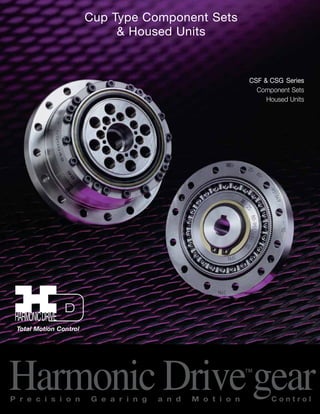
  • 1. Cup Type Component Sets & Housed Units CSF & CSG Series Component Sets Housed Units Total Motion Control Harmonic Drive™gear P r e c i s i o n G e a r i n g a n d M o t i o n C o n t r o l
  • 2. ­­­­­­­­­­­3­­­­­­­­­­­3 ABOUT Harmonic Drive™ Ordering Information 4 Strain Wave Gearing Mechanism 5 System Components 5 Driving Configurations 6 Application Examples 7 Rating Table 10 Technical Terms, Strength & Life 12 Technical Terms, Life 13 Selection Procedure 14 Selection Example 15 COMPONENT TYPE CSF, CSG-2A External Dimension & Shape 16 External Dimension table 18 Grease Lubrication 20 Oil Lubrication 22 Recommended Tolerances for Assembly 24 Wave Generator Bore Modifications 25 Assembly of the Flexspline, Installation 26 Assembly of the Flexspline, Bolts and Screws 27 Assembly of Circular Spline, Bolts 28 Assembly Procedure 29 UNIT TYPES CSF, CSG-2UH External Dimensions of Housed Unit 30 Specifications for Cross Roller Bearing 31 Output Bearing Life 32 Recommended Tolerances for Assembly 34 ENGINEERING DATA Efficiency of Component Set 36 Efficiency of Housed Unit 38 No Load Running Torque 42 Starting Torque and Backdriving Torque 46 Positioning Accuracy 47 Torsional Stiffness 48 Hysteresis Loss 49 Backlash from Oldham Coupling 49 Surface Treatment 49 Contents Harmonic Drive LLC 800-921-3332 Sold & Serviced By: ELECTROMATE Toll Free Phone (877) SERVO98 Toll Free Fax (877) SERV099 www.electromate.com sales@electromate.com
  • 3. Sold & Serviced By: ­­­­­­­­­­­4­­­­­­­­­­­4 Model Customized Specification (special) Size 2A - Component Set such as shape and performance 2UH - Housed Unit Set Name of Model Indicates short cup design Gear Ratio GR = Specification Harmonic Drive™ gearing for Component CSF: Standard version CSG: High torque version Harmonic Drive™ Gear Revolution Harmonic Drive™ precision gear continues to evolve by improving performance and functionality. The CSG achieved a 30% increase in torque capacity. Life (L10) was increased from 7,000 hrs to 10,000 hrs. By pursuing strength and stiffness, a new The CSF achieved tooth profile a reduction in was invented. axial length of The “S” tooth approximately 50% Ratio 30:1 was added for doubled the higher output speeds. torque, life and stiffness. Miniature series was developed to expand the range of Harmonic Drive™ gearing. Tooth Profiles The Harmonic Drive™ CSF/CSG component sets and housed units presented in this catalog incorporate the “S” gear tooth profile. This patented tooth profile provides a significant improvement in gear ope-rating characteristics and performance. The new “S” tooth profile significantly increases the region of tooth engagement. For the traditional tooth profile 15% of the total number of teeth are in contact, while for the new profile up to 30% of the teeth are in contact. The increased number of teeth in engagement results in a 100% increase in torsional stiffness in the low & mid torque ranges. The new tooth profile also features an enlarged tooth root radius, which results in a higher allowable stress and a corresponding increa-se in torque capacity. Furthermore, the enlarged region of tooth enga-gement leads to a more even loading of the Wave Generator bearing, resulting in more than double the life expectancy for the gear. Initial Engagement Full Engagement S Series CSF Series CSG Series Ratio 30:1 Series Miniature Series Ordering Information ELECTROMATE Toll Free Phone (877) SERVO98 Toll Free Fax (877) SERV099 www.electromate.com sales@electromate.com
  • 4. Wave Generator Circular Spline GEARHEAD COMPONENT SET Harmonic Drive LLC 800-921-3332 55­­­­­­­­­­­­­­­­­­­­­­Flexspline Circular Spline (case) Wave Generator (input) Cross Roller Bearing Output Flange Flexspline 0 º Circular Spline Wave Generator Flexspline 90º 360º The Flexspline is elliptically shaped by The Wave Generator and engaged with the Circular Spline at the major elliptical axis. The teeth completely disengage on the minor axis. For each 360 degrees clockwise movement of the Wave Generator,the Flexspline moves counterclockwise by two teeth relative to the Circular Spline. When the Circular Spline is fixed and the Wave generator rotates clockwise, the Flexspline is elastically deformed and rotates counterclockwise relative to the Circular Spline. Principle and Structure System Components The Flexspline is a non-rigid, thin cylindrical cup with external teeth on a slightly smaller pitch diameter than the Circular Spline. It fits over and is held in an elliptical shape by the Wave Generator. The WAVE GENERATOR is a thin raced ball bearing fitted onto an elliptical plug serving as a high efficiency torque converter. The CIRCULAR SPLINE is a rigid ring with internal teeth, engaging the teeth of the Flexspline across the major axis of the Wave Generator. Sold & Serviced By: ELECTROMATE Toll Free Phone (877) SERVO98 Toll Free Fax (877) SERV099 www.electromate.com sales@electromate.com
  • 5. Driving Configurations Driving Configurations A variety of different driving configurations are possible, as shown below. The reduction ratio given in the tables on page 10 and 11 correspond to arrange-ment Sold & Serviced By: ­­­­­­­­­­­6 1, in which the Wave Generator acts as the input element, the Circular Spine is fixed and the Flexspine acts as the output element. 1. Reduction Gearing CS Fixed WG Input FS Output 3. Reduction Gearing WG Fixed FS Input CS Output R + 1 1 Ratio = – [Equation 1] Ratio = [Equation 2] 4. Speed Increaser Gearing WG Fixed CS Input FS Output 7. Differential Gearing WG Control Input CS Main Drive-Input FS Main Drive-Output Numerous differential functions can be obtained by combinations of the speed and rotational direction of the three basic elements. Input and output in same direction. 5. Speed Increaser Gearing CS Fixed FS Input WG Output Ratio = [Equation 3] 1 Ratio = [Equation 6] R1 R + 1 1 R R + 1 Ratio = R [Equation 4] R + 1 Ratio = – [Equation 5] R Input and output in opposite direction. Input and output in opposite direction. Input and output in same direction. 2. Reduction Gearing FS Fixed WG Input CS Output ELECTROMATE Toll Free Phone (877) SERVO98 Toll Free Fax (877) SERV099 www.electromate.com sales@electromate.com
  • 6. Example Harmonic Drive LLC 800-921-3332 7­­­­­­­­­­­Application ­­­­­­­­­­­7 The CSF Cup-Style Component Set achieves higher performance than the Pancake Style Component Set in the same package size. CSF Series Component Set Pancake Type Component Set Sold & Serviced By: ELECTROMATE Toll Free Phone (877) SERVO98 Toll Free Fax (877) SERV099 www.electromate.com sales@electromate.com
  • 7. Application Example Sold & Serviced By: ­­­­­­­­­­­8­­­­­­­­­­­8 Tool Changer Multi-joint Robot ELECTROMATE Toll Free Phone (877) SERVO98 Toll Free Fax (877) SERV099 www.electromate.com sales@electromate.com
  • 8. Example Harmonic Drive LLC 800-921-3332 9­­­­­­­­­­­9­­­­­­­­­­­Application Housed Unit - Direct Connection to Servo Motor Housed Unit - Input Shaft Option Sold & Serviced By: ELECTROMATE Toll Free Phone (877) SERVO98 Toll Free Fax (877) SERV099 www.electromate.com sales@electromate.com
  • 9. CSF Rating Table Sold & Serviced By: ­­­­­­­­­­­10 Table 1 Size Ratio Rated Limit for Limit for Limit for Maximum Limit for Moment Torque Repeated Average Momentary Input Average of at Peak Torque Peak Speed Input Inertia 2000 Torque Torque Speed Tr rpm Nm Nm Nm rpm rpm Nm in-lb Nm in-lb Nm in-lb Nm in-lb Oil Grease Oil Grease x10-4kg•m2 x10-5kgf•m•s2 30 0.9 8 1.8 16 1.4‑ 12 3.3 29 8 50 1.8 16 3.3 29 2.3‑ 20 6.6 58 14000 8500 6500 3500 0.003 0.0031 100 2.4 18 4.8 42 3.3‑ 29 9.0 80 30 2.2 19 4.5 40 3.4‑ 30 8.5 75 11 50 3.5 31 8.3 73 5.5‑ 49 17 150 14000 8500 6500 3500 0.012 0.012 100 5.0 44 11 97 8.9‑ 79 25 221 30 4.0 35 9.0 80 6.8 60 17 150 14 50 5.4 48 18 159 6.9 61 35 310 14000 8500 6500 3500 0.033 0.034 80 7.8 69 23 204 11 97 47 416 100 7.8 69 28 248 11 97 54 478 30 8.8 78 16 142 12 106 30 266 50 16 142 34 301 26 230 70 620 17 80 22 195 43 381 27 239 87 770 10000 7300 6500 3500 0.079 0.081 100 24 212 54 478 39 345 108 956 120 24 212 54 478 39 345 86 761 30 15 133 27 239 20 177 50 443 50 25 221 56 496 34 301 98 867 20 80 34 301 74 655 47 411 127 1124 10000 6500 6500 3500 0.193 0.197 100 40 354 82 726 49 434 147 1301 120 40 354 87 770 49 434 147 1301 160 40 354 92 814 49 434 147 1301 30 27 239 50 443 38 336 95 841 50 39 345 98 868 55 487 186 1646 25 80 63 558 137 1212 87 770 255 2257 7500 5600 5600 3500 0.413 0.421 100 67 593 157 1389 108 956 284 2513 120 67 593 167 1478 108 956 304 2690 160 67 593 176 1558 108 956 314 2779 30 54 478 100 885 75 664 200 1770 50 76 673 216 1912 108 956 382 3381 32 80 118 1044 304 2690 167 1478 568 5027 7000 4800 4600 3500 1.69 1.72 100 137 1212 333 2947 216 1912 647 5726 120 137 1212 353 3124 216 1912 686 6071 160 137 1212 372 3292 216 1912 686 6071 50 137 1212 402 3558 196 1735 686 6071 80 206 1823 519 4593 284 2513 980 8673 40 100 265 2345 568 5027 372 3292 1080 9558 5600 4000 3600 3000 4.50 4.59 120 294 2602 617 5460 451 3991 1180 10443 160 294 2602 647 5726 451 3991 1180 10443 50 176 1558 500 4425 265 2345 950 8408 80 313 2770 706 6248 390 3452 1270 11240 45 100 353 3124 755 6682 500 4425 1570 13895 5000 3800 3300 3000 8.68 8.86 120 402 3558 823 7284 620 5487 1760 15576 160 402 3558 882 7806 630 5576 1910 16904 50 245 2168 715 6328 350 3098 1430 12656 80 372 3292 941 8328 519 4593 1860 16461 50 100 470 4160 980 8673 666 5894 2060 18231 4500 3500 3000 2500 12.5 12.8 120 529 4682 1080 9558 813 7195 2060 18231 160 529 4682 1180 10443 843 7461 2450 21683 50 353 3124 1020 9027 520 4602 1960 17346 80 549 4859 1480 13098 770 6815 2450 21683 58 100 696 6160 1590 14072 1060 9381 3180 28143 4000 3000 2700 2200 27.3 27.9 120 745 6593 1720 15222 1190 10532 3330 29471 160 745 6593 1840 16284 1210 10709 3430 30356 ELECTROMATE Toll Free Phone (877) SERVO98 Toll Free Fax (877) SERV099 www.electromate.com sales@electromate.com
  • 10. Rating Table Table 3 CSG Rating Table Size Ratio Rated Limit for Limit for Limit for Maximum Limit for Moment Torque Repeated Average Momentary Input Average of at 2000 Peak Torque Peak Speed Input Inertia Tr Torque Torque rpm Speed rpm rpm Nm in-lb Nm in-lb Nm in-lb Nm in-lb Oil Grease Oil Grease x10-4kg•m2 x10-5kgf•m•s2 Harmonic Drive LLC 800-921-3332 1­­­­­­­­­­­1 50 7.0 62 23 204 9 80 46 407 14 80 10 89 30 266 14 124 61 540 14000 8500 6500 3500 0.033 0.0034 100 10 89 36 319 14 124 70 620 50 21 186 44 390 34 301 91 805 17 80 29 257 56 496 35 310 113 1000 10000 7300 6500 3500 0.079 0.081 100 31 274 70 620 51 451 143 1266 120 31 274 70 620 51 451 112 991 50 33 292 73 646 44 389 127 1124 80 44 389 96 850 61 540 165 1460 20 100 52 460 107 947 64 566 191 1690 10000 6500 6500 3500 0.193 0.197 120 52 460 113 1000 64 566 191 1690 160 52 460 120 1062 64 566 191 1690 50 51 451 127 1124 72 637 242 2142 80 82 726 178 1575 113 1000 332 2938 25 100 87 770 204 1805 140 1239 369 3266 7500 5600 5600 3500 0.413 0.421 120 87 770 217 1920 140 1239 395 3496 160 87 770 229 2027 140 1239 408 3611 50 99 876 281 2487 140 1239 497 4399 80 153 1354 395 3496 217 1920 738 6531 32 100 178 1575 433 3832 281 2487 841 7443 7000 4800 4600 3500 1.69 1.72 120 178 1575 459 4062 281 2487 892 7894 160 178 1575 484 4283 281 2487 892 7894 50 178 1575 523 4629 255 2257 892 7894 80 268 2372 675 5974 369 3266 1270 11240 40 100 345 3053 738 6531 484 4283 1400 12390 5600 4000 3600 5000 4.50 4.59 120 382 3381 802 7098 586 5186 1530 13541 160 382 3381 841 7443 586 5186 1530 13541 Table 2 Size Ratio Rated Limit for Limit for Limit for Maximum Limit for Moment Torque Repeated Average Momentary Input Average of at 2000 Peak Torque Peak Speed Input Inertia T r Torque Torque rpm Speed rpm rpm Nm in-lb Nm in-lb Nm in-lb Nm in-lb Oil Grease Oil Grease x10-4kg•m2 x10-5kgf•m•s2 50 490 4337 1420 12567 720 6372 2830 25046 80 745 6593 2110 187 1040 9204 3720 32922 65 100 951 8416 2300 20355 1520 13452 4750 42038 3500 2800 2400 1900 46.8 47.8 120 951 8416 2510 22214 1570 13895 4750 42038 160 951 8416 2630 23276 1570 13895 4750 42038 50 872 7717 2440 21594 1260 11151 4870 43100 80 1320 11682 3430 30356 1830 16196 6590 58322 80 100 1700 15045 4220 37347 2360 20886 7910 70004 2900 2300 2200 1500 122 124 120 1990 17612 4590 40622 3130 27701 7910 70004 160 1990 17612 4910 43454 3130 27701 7910 70004 50 1180 10443 3530 31241 1720 15222 6660 58941 80 1550 13718 3990 35312 2510 22214 7250 64163 90 100 2270 20090 5680 50268 3360 29736 9020 79827 2700 2000 2100 1300 214 218 120 2570 22745 6160 54516 4300 38055 9800 86730 160 2700 23895 6840 60534 4300 38055 11300 100005 50 1580 13983 4450 39383 2280 20178 8900 78765 80 2380 21063 6060 53631 3310 29294 11600 102660 100 100 2940 26019 7350 65048 4630 40976 14100 124785 2500 1800 2000 1200 356 363 120 3180 28143 7960 70446 5720 50622 15300 135405 160 3550 31418 9180 81243 5720 50622 15500 137175 ­­­­­­­­­­­11 Sold & Serviced By: ELECTROMATE Toll Free Phone (877) SERVO98 Toll Free Fax (877) SERV099 www.electromate.com sales@electromate.com
  • 11. CSG Rating Table Sold & Serviced By: ­­­­­­­­­­­12 Table 4 Size Ratio Rated Limit for Limit for Limit for Maximum Limit for Moment Torque Repeated Average Momentary Input Average of at 2000 Peak Torque Peak Speed Input Inertia Tr Torque Torque rpm Speed rpm rpm Nm in-lb Nm in-lb Nm in-lb Nm in-lb Oil Grease Oil Grease x10-4kg•m2 x10-5kgf•m•s2 50 229 2,027 650 5,753 345 3,053 1,235 10,930 80 407 3,602 918 8,124 507 4,487 1,651 14,611 45 100 459 4,062 982 8,691 650 5,753 2,041 18,063 5,000 3,800 3,300 3,000 8.68 8.86 120 523 4,629 1,070 9,470 806 7,133 2,288 20,249 160 523 4,629 1,147 10,151 819 7,248 2,483 21,975 80 484 4,283 1,223 10,824 675 5,974 2,418 21,399 50 100 611 5,407 1,274 11,275 866 7,664 2,678 23,700 4,500 3,500 3,000 2,500 12.5 12.8 120 688 6,089 1,404 12,425 1,057 9,354 2,678 23,700 160 688 6,089 1,534 13,576 1,096 9,700 3,185 28,187 80 714 6,319 1,924 17,027 1,001 8,859 3,185 28,187 58 100 905 8,009 2,067 18,293 1,378 12,195 4,134 36,586 4,000 3,000 2,700 2,200 27.3 27.9 120 969 8,576 2,236 19,789 1,547 13,691 4,329 38,312 160 969 8,576 2,392 21,169 1,573 13,921 4,459 39,462 80 969 8,576 2,743 24,276 1,352 11,965 4,836 42,799 65 100 1,236 10,939 2,990 26,462 1,976 17,488 6,175 54,649 3,500 2,800 2,400 1,900 46.8 47.8 120 1,236 10,939 3,263 28,878 2,041 18,063 6,175 54,649 160 1,236 10,939 3,419 30,258 2,041 18,063 6,175 54,649 ELECTROMATE Toll Free Phone (877) SERVO98 Toll Free Fax (877) SERV099 www.electromate.com sales@electromate.com
  • 12. Circular Spline Technical Terms Harmonic Drive LLC 800-921-3332 1­­­­­­­­­­­3 Start Routine Abnormal Impact Torque Start Stop Speed Cycle Number of Rotations of Wave Generator Time Time Load Torque Repeated Peak Torque Load Torque Momentary Peak Torque Flexspline Definition of Ratings Rated Torque (Tr) Rated torque indicates allowable continuous load torque at 2000 rpm input speed. Limit for Repeated Peak Torque (refer to figure 1) During acceleration a deceleration the Harmonic Drive™ gear experiences a peak torque as a result of the moment of inertia of the output load. Limit for Average Torque In cases where load torque and input speed vary, it is necessary to calculate an average value of load torque. The table indicates the limit for average torque. The average torque calculated must not exceed this limit. Limit for Momentary Peak Torque (refer to figure 1) The gear may be subjected to momentary peak torques in the event of a collision or emergency stop. The magnitude and frequency of occurrence of such peak torques must be kept to a minimum and they should, under no circumstance, occur during normal operating cycle. The allowable number of occurrences of the momentary peak torque may be calculated by using equation 7 on page 13. Also see section “strength and life”. Figure 1 Maximum Input Speed, Limit for average input speed Do not exceed the allowable rating. Moment of Inertia The rating indicates the moment of inertia reflected to the wave generator (gear input). Strength and Life The non-rigid Flexspline is subjected to repeated deflections, and its strength determines the torque capacity of the Harmonic Drive™ gear. The values given for Rated Torque at Rated Speed and for the allo-wable Repeated Peak Torque are based on an infinite fatigue life for the Flexspline. The torque that occurs during a collision must be below the momentary peak torque (impact torque). The maximum number of occurrences is given by the equation below. [Equation 7] 1.0 X 10⁴ n: Input speed before collision (r/min) N = ____________ 2 X n 60 X t t: Time interval during collision (sec) Please note: If this number is exceeded, the Flexspline may experience a fatigue failure. Ratcheting phenomenon When excessive torque is applied while the gear is in motion, the teeth between the Circular Spline and Flexspline may not engage properly. This phenomenon is called ratcheting and the torque at which this occurs is called ratcheting torque. Ratcheting may cause the Flexspline to become non-concentric with the Circular Spline. (See figure 1 & 2 on page 13) Operating in this condition may result in shortened life and a Flexspline fatigue failure. Figure 2 This condition is called “dedoidal”. Note! When ratcheting occurs, the teeth mesh abnormally as shown above. Vibration and Flexspline damage may occur. Once ratcheting occurs, the teeth wear excessively and the ratcheting torque may be lowered. Sold & Serviced By: ELECTROMATE Toll Free Phone (877) SERVO98 Toll Free Fax (877) SERV099 www.electromate.com sales@electromate.com
  • 13. Technical Terms CSF Ratcheting Torque Table 4 Nm Size Ratio Sold & Serviced By: ­­­­­­­­­­­14 30 50 80 100 120 160 8 11 12 - 14 - - 11 29 34 - 43 - - 14 59 88 110 84 - - 17 100 150 200 160 120 - 20 170 220 350 260 240 220 25 340 450 680 500 470 450 32 720 980 1400 1000 980 980 40 - 1800 2800 2100 1900 1800 45 - 2700 3900 3100 2800 2600 50 - 3700 5400 4100 3800 3600 58 - 5800 8200 6400 5800 5600 65 - 7800 11000 9400 8300 8000 80 - 14000 22000 16000 15000 14000 90 - 20000 30000 23000 21000 20000 100 - 29000 44000 33000 30000 28000 Table 5 Nm CSF Buckling Torque Size All Ratio 8 35 11 90 14 190 17 330 20 560 25 1000 32 2200 40 4300 45 5800 50 8000 58 12000 65 17000 80 31000 90 45000 100 58000 CSG Ratcheting Torque Table 6 Nm Size Ratio 50 80 100 120 160 14 110 140 100 - - 17 190 260 200 150 - 20 280 450 330 310 280 25 580 880 650 610 580 32 1200 1800 1300 1200 1200 40 2300 3600 2700 2400 2300 Table 7 Nm CSG Buckling Torque Size All Ratio 14 260 17 500 20 800 25 1700 32 3500 40 6700 17 16 10 ) 1 9 = Torque 8 7 Rated 6 ( Torque 5 4 Load 3 2 1 Buckling Torque Racheting Torque Momentary Peak Torque 105 106 107 108 109 0 Total Number of Input Rotations 1010 Life of the Wave Generator Fatigue Strength of Flexspline Repeated Peak Torque Rated Torque The Life of a Wave Generator The normal life of a gear is determined by the life of the wave generator bearing. The life may be calculated by using the input speed and the output load torque. Rated Lifetime Ln : (n = 10 or 50) L10 CSF : 7,000 CSG: 10,000 L50 CSF : 35,000 CSG : 50,000 Equation for the expected life of the wave generator under normal operating conditions is given by the equation below. [Equation 8] Lh = Ln • ( Tr )3 • ( Nr ) Tav Nav Lh : Expected Life, hours Ln : Rated Lifetime at L10 or L50 Tr : Rated Torque (Tables 1, 2, 3) Nr : Rated input speed (2000 rpm) Tav : Average load torque on output side (page 14) Nav : Average input speed (page 14) Relative Torque Rating The chart below shows the various torque specifications relative to rated torque. Rated Torque has been normalized to 1 for comparison. Figure 3 14 ELECTROMATE Toll Free Phone (877) SERVO98 Toll Free Fax (877) SERV099 www.electromate.com sales@electromate.com
  • 14. Harmonic Drive LLC 800-921-3332 1­­­­­­­­­­­5 T 1 T 2 T 3 T 4 T n t 1 t 2 t 3 t 4 t n n 1 n 2 n 3 n 4 n n + Torque _ rpm n 1 n n are an average value. Time 2 n Time OK OK OK OK OK NG NG NG NG NG Size Selection Generally, the operating conditions consist of fluctuating torques and output speeds. Also, an unexpected impact output torque must be considered. The proper size can be determined by converting fluctuating load tor-que into average load torque and equivalent load torque. This proce-dure involves selecting the size based on load torque for component sets. This procedure does not consider the life of the output bearing for housed units. Determining the life of the output bearing for various axial, radial, and moment loads is outlined on page 31. Figure 4 Parameters Load Torque Tn (Nm) Time tn (sec) Output Speed nn (rpm) Normal Operating Pattern Acceleration T1,t1, n1 Regular Operation T2,t2, n2 Deceleration T3,t3, n3 Dwell T4,t4, n4 Maximum RPM Max output speed no maximum Max input speed ni maximum Impact Torque Ts,ts, ns Ratings Rated Torque Tr Rated Speed nr =2000 rpm Flow Chart for selecting a size Please use the flowchart shown below for selecting a size. Operating conditions must not exceed the performance ratings as described on page 12. Calculation of the average output torque Tav = 3 n1•t1•|T1| 3+n2•t2•|T2| 3+... nn•tn•|Tn| 3 n1•t1+n2•t2+... nn tn Selection of tentative size under the condition shown below. Average Output Speed Nav = n1t1 + n2t2 ... + nntn t1+t2 ... + tn Determine Gear Ratio ni max <= R no max ni max may be limited by the motor. Calculation of the average input speed ni av = no av •R Calculation of maximum input speed ni max = no max •R ni av <= Limit for average speed ni max <= Limit for maximum speed Confirm if T1 and T3 are less than the repeated peak torque specification. Confirm if Ts (impact torque) is less than the momentary peak torque specification. Calculate the allowable number of rotations during impact torque. Ns = 104 ••••••Ns <= 1.0X10⁴ 2• ns•R •ts 60 Calculate wave generator life. Lh = Ln • ( Tr )3 •( nr ) Tav ni av Make sure that the calculated life is suitable for the application. Gear is suitable for torque and speed requirements Also consider output bearing, environment, etc. Consider a different Size or change operating requirements Selection Procedure Sold & Serviced By: ELECTROMATE Toll Free Phone (877) SERVO98 Toll Free Fax (877) SERV099 www.electromate.com sales@electromate.com
  • 15. Selection Example Sold & Serviced By: ­­­­­­­­­­­16 Values of an each Load Torque Pattern Load Torque Tn (Nm) no max = 14 rpm Time tn (sec) ni max = 1800 rpm Output Speed nn (rpm) Normal Operating Pattern Acceleration T1 = 400 Nm, t1 = 0.3 sec, n1 = 7 rpm Ts = 500 Nm, ts = 0.15 sec, ns = 14 rpm Regular Operation Stop T2 = 320 Nm, t2 = 3 sec, n2 = 14 rpm Deceleration T3 = 200 Nm, t3 = 0.4 sec, n3 = 7 rpm L10 = 7000 hrs. Dwell T4 = 0 Nm, t4 = 0.2 sec, n4 = 0 rpm Oil Lubrication Tav (Nm) 3 7rpm•0.3sec•|400Nm|3+14rpm•3sec•|320Nm|3+7rpm•0.4sec•|200Nm|3 Tav = 7rpm•0.3sec+14rpm•3sec+7rpm•0.4sec Tav =319Nm<451Nm (for CSF-40-120-2A-GR) no av (rpm) 7rpm•0.3sec+14rpm•3sec+7rpm•0.4sec no av = = 12rpm 0.3sec + 3sec + 0.4sec + 0.2sec (R) 1800 rpm = 128.6 > 120 14 rpm n av = 12 rpm •120 = 1440 rpm n max ni max (rpm) n max = 14 rpm •120 = 1680 rpm n av =1440rpm<3600 rpm (for CSF-40-120-2A-GR) n max=1680rpm<5600 rpm (for CSF-40-120-2A-GR) Confirm that T1 and T3 are within a T 1 ,T 3 (Nm) T 1 =400Nm<617Nm (for CSF-40-120-2A-GR) T 3 =200Nm<617Nm (for CSF-40-120-2A-GR) T s (Nm) T s = 500Nm<1180Nm (for CSF-40-120-2A-GR) (N s ) Calculate an allowable number of rotation(Ns) and confirm <= 1.0 x 10⁴ 104 N S = = 1190 < 1.0X10⁴ 14rpm•120 2• • 0.15sec 60 ( 294Nm L 10 = 7000 • ) 3 • ( 2000 rpm ) 319Nm 1440 rpm L 10 =7610>7000 (L B10 ) OK OK OK OK OK CSF-40-120-2A-GR i o i i i Calculate a life time. ELECTROMATE Toll Free Phone (877) SERVO98 Toll Free Fax (877) SERV099 www.electromate.com sales@electromate.com
  • 16. External Dimension & Shape H2 øU2 Harmonic Drive LLC 800-921-3332 1­­­­­­­­­­­7 1 2 3 4 5 6 7 CSF-14,17,20,25,32,45,58,90 CSF-40,50,65,80,100 Wave Generator Components 1. Ball Separator 2. Wave Generator Bearing 3. Wave Generator Plug 4. Insert 5. Rub Washer 6. Snap Ring 7. Wave Generator Hub ‑ There is a difference in appearance of the the ball separator between CSF and CSG. (CSG size 14 and 17 use the same ball separator as CSF. CSF all sizes CSG-20 and above Sold & Serviced By: ELECTROMATE Toll Free Phone (877) SERVO98 Toll Free Fax (877) SERV099 www.electromate.com sales@electromate.com
  • 17. External Dimension & Shape 1 L–øM Z Dowel Pin Option In cases where the gear will see loads near the Momentary Peak Torque level, the use of additional dowel pins in addition to the screws is recommended. Dowel pin holes are manufactured by reamer and the dimensions are shown. In addition, the CSF has a different number of dowel pin holes than the CSG. Sold & Serviced By: ­­­­­­­­­­­18 C 2 R0.3 C 1 d Flexspline Dowel Pin Hole 2–N F L–øM R–øS T Q øZ 1 øZ 2 øI h6 øa øJ øK H6 øa øA h6 1 øU d 2 d 3 d 1 Y B D 2–Nc 2–øP E F 1 O b H 0 1-0.1 c G W øV H7 X Q 1 3 P7-0.006 -0.016 1.5+0.1 0 e 2-f A 2– øcc T 2 2– NF øZ3 (Flexspline Interface #8) Detailed drawings are also available. No key on WG hub for #8, 11, 14, 17. ELECTROMATE Toll Free Phone (877) SERVO98 Toll Free Fax (877) SERV099 www.electromate.com sales@electromate.com
  • 18. External Dimensions Table 8 (mm) 8 11 14 17 20 25 32 40 øA h6 30 40 50 60 70 85 110 135 Harmonic Drive LLC 800-921-3332 1­­­­­­­­­­­9 B CSF 22.10 -0.3 25.8 0 -0.7 28.5 0 -0.8 32.5 0 -0.9 33.5 0 -1.0 37 0 -1.0 44 0 -1.1 53 0 -1.1 CSG - - 28.5 0 -0.4 32.5 0 -0.4 33.5 0 -0.4 37 0 -0.5 44 0 -0.6 53 0 -0.6 C1 12.5+0.2 0 14.5+0.4 0 17.5+0.4 0 20+0.5 0 21.5+0.6 0 24+0.6 0 28+0.6 0 34+0.6 0 C2 9.6 11.3 11 12.5 12 13 16 19 D 2.7 2 2.4 3 3 3 3.2 4 E - 2 2 2.5 3 3 3 4 F 4.5 5 6 6.5 7.5 10 14 17 G CSF - - 0.4 0.3 0.1 2.1 2.5 3.3 CSG - - 1.4 1.6 1.5 3.5 4.2 5.6 H 1 0 -0.1 CSF 12 16 17.6 19.5 20.1 20.2 22 27.5 CSG - - 18.5 20.7 21.5 21.6 23.6 29.7 H2 - - - - - - - 0.4 øI h6 Ratio=30 - 31 38 48 54 67 90 110 Ratio=30 - 31 38 48 55 68 90 - øJ 12.3 17.8 23 27.2 32 40 52 64 øK H6 6 6 11 10 16 20 26 32 L CSF 8 8 6 12 12 12 12 12 CSG - - 8 16 16 16 16 16 øM 2.2 2.9 3.5 3.4 3.5 4.5 5.5 6.6 NC M2 M2.5 M3 M3 M3 M4 M5 M6 NF - - M3 M3 M3 M4 M5 M6 O 3 3 6 6.5 4 6 7 9 øP 2.2 2.9 - - 3.5 4.5 5.5 6.6 Q(PCD) 25.5 35 44 54 62 75 100 120 R - 6 6 6 8 8 8 8 øS - 3.4 4.5 5.5 5.5 6.6 9 11 T1 (PCD) - 12 17 19 24 30 40 50 T2 (PCD) - 15.2 18.5 21.5 27 34 45 56 øU1 7 11 14 18 21 26 26 32 øU2 - - - - - - - 32 øV (H7)standard 3 5 6 8 9 11 14 14 maximum - - 8 10 13 15 15 20 WJs9 - - - - 3 4 5 5 X - - - - 10.4+0.1 0 12.8+0.1 0 16.3+0.1 0 16.3+0.1 0 Y - C0.2 C0.3 C0.4 C0.4 C0.4 C0.4 C0.4 øZ1 0.1 0.2 0.25 0.20 0.25 0.25 0.25 0.3 øZ2 - 0.2 0.25 0.25 0.25 0.3 0.5 0.5 øZ3 - 0.02 0.02 0.02 0.02 0.02 0.02 0.02 øa Minimum 21.5 30 38 45 53 66 86 106 b housing clearance 11.34 14 17.1 19 20.5 23 26.8 33 c - - 1 1 1.5 1.5 1.5 2 ø cc H7 CSF - 2 3 3 3 4 5 6 CSG - - 2.5 3 3 4 5 5 d1 C0.3 C0.4 C0.4 C0.4 C0.4 C0.4 C0.4 C0.4 d2 C0.3 C0.4 C0.4 C0.4 C0.4 C0.4 C0.4 C0.4 d3 C0.3 C0.3 C0.5 C0.5 C0.5 C0.5 C0.5 C0.5 e 2 3 2.5 3 - - - - f M2X3 M3X4 M3X4 M3X6 - - - - Weight (kg) 0.026 0.05 0.09 0.15 0.28 0.42 0.89 1.7 Sold & Serviced By: ELECTROMATE Toll Free Phone (877) SERVO98 Toll Free Fax (877) SERV099 www.electromate.com sales@electromate.com
  • 19. External Dimensions Sold & Serviced By: ­­­­­­­­­­­20 Table 9 (mm) 45 50 58 65 80 90 100 øA h6 155 170 195 215 265 300 330 B 58.5 0 -1.2 64 0 -1.3 75.5 0 -1.3 83 0 -1.3 101 0 -1.3 112.5 0 -1.4 125 0 -1.6 C1 38+0.6 0 41+0.6 0 48+0.6 0 52.5+0.6 0 64+0.6 0 71.5+0.8 0 79+1.0 0 C2 20.5 23 27.5 30.5 37 41 46 D 4.5 5 5.8 6.5 8 9 10 E 4 4 5 5 6 6 6 F 19 22 25 29 36 41 46 G CSF 3.7 4.2 4.8 5.8 6.6 7.5 8.3 CSG 6.3 7 8.2 9.5 — — — H1 0 -0.1 CSF 27.9 32 34.9 40.9 49.1 48.2 56.7 CSG 30.5 34.8 38.3 44.6 — — — H2 — 0.8 — 2.2 3.1 — 4.5 øI h6 1/30 except 124 135 156 177 218 245 272 1/30 — — — — — — — øJ 72 80 92.8 104 128 144 160 øK H6 36 40 46 52 65 72 80 L CSF 12 12 12 12 16 16 16 CSG 16 16 16 16 — — — øM 9 9 11 11 11 14 14 NC M8 M8 M10 M10 M10 M12 M12 NF M6 M8 M8 M8 M8 M12 M10 O 12 13 15 15 15 18 20 øP 9 9 11 11 11 14 14 Q(PCD) 140 150 175 195 240 270 300 R 8 8 8 8 10 8 12 øS 13.5 15.5 15.5 18 18 22 22 T1 (PCD) 54 60 70 80 100 110 130 T2 (PCD) 61 68 79 90 114 120 142 øU1 32 32 40 48 55 60 65 øU2 — 32 — 48 55 — 65 øV (H7)Standard 19 19 22 24 28 28 28 Maximum 20 20 25 30 35 37 40 WJs9 6 6 6 8 8 8 8 X 21.8+0.1 0 21.8+0.1 0 24.8+0.1 0 27.3+0.2 0 31.3+0.2 0 31.3+0.2 0 31.3+0.2 0 Y C0.4 C0.8 C0.8 C0.8 C0.8 C0.8 C0.8 øZ1 0.5 0.5 0.5 0.5 0.5 1.0 1.0 øZ2 0.75 0.75 0.75 1.0 1.0 1.0 1.0 øZ3 0.02 0.02 0.02 0.02 0.02 0.02 0.02 øa Minimum 119 133 154 172 212 239 265 b housing clearance 36.5 39 46.2 50 61 68.5 76 c 2 2 2.5 2.5 3 3 3 øcc H7 6 8 8 8 8 12 10 d1 C0.4 C0.4 C0.4 C0.4 C0.4 C0.4 C0.4 d2 C0.4 C0.4 C0.4 C0.4 C0.4 C0.4 C0.4 d3 C0.5 C0.5 C0.5 C0.5 C0.5 C0.5 C0.5 e — — — — — — — f — — — — — — — Weight (kg) 2.3 3.2 4.7 6.7 12.4 17.6 23.5 The pilot diameter for the Circular spline can be either ØI or ØA. Surface A is the recommended mounting surface. The following parameters can be modified to accommodate customer-specific requirements. Wave Generator: ØV, X, W Flexspline: R, ØS Circular Spline: ØM, L ELECTROMATE Toll Free Phone (877) SERVO98 Toll Free Fax (877) SERV099 www.electromate.com sales@electromate.com
  • 20. Grease lubricant is the standard for the CSF and CSG units. The temperature range is shown below. Lubricant Type Grease Harmonic Grease SK-1A Grease Harmonic Grease SK-2 Grease Harmonic Grease 4B-No.2 Oil Industrial gear oil #2(high pressure) ISO VG68 Lubricant Type Temperature Grease SK-1A 0ºC~+40ºC Grease SK-2 0ºC~+40ºC Grease 4B-No.2 -10ºC~+70ºC Oil ISO VG68 0ºC~+40ºC Harmonic Grease SK-1A - This grease is developed for a Harmonic Drive™ gear and features good durability and efficiency. Harmonic Grease SK-2 - This grease is developed for a small size Harmonic Drive™ gear and features smooth rotation of the Wave Generator since high pressure additive is liquefied. Harmonic Grease 4BNo.2 - This grease is developed for Harmonic Drive™ gears and features long life and a wide range of temperature. Note 1 - Grease lubrication must have proper sealing, this is essential for 4B No.2. Rotating part: Oil seal with spring is needed. Mating part: O ring or seal adhesive is needed. Note 2 - The grease has the highest deterioration rate in the region where the grease is subjected to the greatest shear (near wave generator). Its viscosity is between JIS No.0 and No.00 depending on the operation. Characteristics of Grease Grease SK-1A SK-2 4BNo.2 Durability O O • Fretting Resistance O O • Low Temp Δ Δ • Grease Leakage • • Δ •: Excellent O: Good Δ: Exercise Caution Recommended Grease Grease SK-1A SK-2 4B No.2 Base Oil Refined mineral hydrocarbon Refined mineral hydrocarbon Hydrocarbon type synthetic base oil base oil oil and polymer Thickening Agent Lithium soap Lithium soap Urea thickener thickener Additive Organic molybdenum, etc. Organic molybdenum, etc. Organic molybdenum, etc.s NLGI Consistency No. No.2 No.2 No.1.5 Viscosity (25C) cSt 265 to 295 265 to 295 290 to 320 Melting Point 197ºC 198ºC 247ºC Color Yellow Green Light Yellow Life 5 Years in Airtight Container Ratio1/30 Size 14 17 20 25 32 SK-1A — — O O O SK-2 O O — — — 4BNo.2 Δ Δ • • • •: recommended grease for long life and high load O: Standard Δ: Semistandard Ratio 1/50 and above Size 14 17 20 25 32 40 45 50 58 65 SK-1A — — O O O O O O O O SK-2 O O Δ Δ Δ Δ — — — — 4BNo.2 • • • • • • • • • • •: recommended grease for long life and high load O: Standard Δ: Semistandard Lubrication ­­­­­­­­­­­21 Sold & Serviced By: ELECTROMATE Toll Free Phone (877) SERVO98 Toll Free Fax (877) SERV099 www.electromate.com sales@electromate.com
  • 21. Recommended Tolerance for Inner Case Table 10 mm Size 8 11 14 17 20 25 32 40 45 50 58 65 80 90 100 øA 21.5 30 38 45 53 66 86 106 119 133 154 172 212 239 265 b 11.34 14 17.1 19 20.5 23 26.8 33 36.5 39 46.2 50 61 68.5 76 c 0.5 0.5 1 1 1.5 1.5 1.5 2 2 2 2.5 2.5 3 3 3 ød 13 16 16 26 30 37 37 45 45 45 56 62 67 73 79 Grease Usage Table 11 grams Size 8 11 14 17 20 25 32 40 45 50 58 65 80 90 100 Horizontal 1.2 2.9 5.5 10 16 30 60 110 170 220 360 460 850 1150 1500 Output Up 1.4 3.5 7 12 18 35 70 125 190 240 380 500 900 1300 1700 Output Down 1.8 4.4 8.5 14 21 40 80 145 220 275 460 600 1000 1500 1900 Sold & Serviced By: ­­­­­­­­­­­22 b c ø a ø d CIRCULAR SPLINE FLEXSPLINE WAVE GENERATOR Apply thin coat to avoid rust Fill the toothbed with grease Fill the toothbed with grease Apply grease to Oldham coupling Apply thin coating of grease before installation Pack bearing with grease while slowly rotating bearing Apply grease to inner surface in accordance with a value shown above. Fill cavity between retainer and insert with grease when using in high speed HORIZONTAL OUTPUT UP OUTPUT DOWN This must be 2X C. Fill 50% of this space with grease c Apply grease to inner surface in accordance with quantity shown in table. Apply grease to inner surface in accordance with a quantity shown in table. Apply grease to inner surface in accordance with a value shown above. c Grease Proper lubrication of the gear is essential for high performance and reliability. Recommend grease: SK-2 for sizes 8 thru 17 SK-1A for size 20 thru 65 Note: Harmonic Drive™ component sets are shipped with a rust-preventative oil. This oil is not sufficient for lubricating the gear, however, the appropriate grease may be applied directly on top of this rust-preventative oil. Counter bore for bolt head. Lubrication ELECTROMATE Toll Free Phone (877) SERVO98 Toll Free Fax (877) SERV099 www.electromate.com sales@electromate.com
  • 22. Lubrication ­­­­­­­­­­­23 Number of Rotations Grease Change Interval for Tav < Tr LGTn 4B No.2 SK-1A SK-2 Wave Generator Life 20 40 60 80 100 120 Grease Temperature (Cº) 1010 109 108 107 Grease Life Grease Change The wear characteristics of the gear are strongly influenced by the condition of the grease lubrication. The condition of the grease is affected by the ambient temperature. The graph shows the maximum number of input rotations for various temperatures. This graph applies to applications where the average load torque does not exceed the rated torque. Note: Recommended Grease: SK-1A or SK-2 In cases where the rated torque is exceeded, calculate the grease change interval using the equation shown below. Equation where average load torque exceeds rated torque [Equation 9] LGT = LGTn X ( Tr )3 Tav Symbol of Equation LGT Grease change (over rated torque), input rotations LGTn Grease change (below rated torque), input rotations (From Graph) Tr Rated Torque Tav Average load torque on output Sold & Serviced By: ELECTROMATE Toll Free Phone (877) SERVO98 Toll Free Fax (877) SERV099 www.electromate.com sales@electromate.com
  • 23. Lubrication Oil Level of Horizontal Usage Table 13 mm Size 8 11 14 17 20 25 32 40 45 50 58 65 80 90 100 A 6 8 10 12 14 17 24 31 35 38 44 50 59 66 74 Oil Level for Horizontal Usage Oil Level of Vertical Usage Table 14 mm Size 8 11 14 17 20 25 32 40 45 50 58 65 80 90 100 B 2 2.3 2.5 3 3 5 7 9 10 12 13 15 19 22 25 Sold & Serviced By: ­­­­­­­­­­­24 A Oil Level B B Output on Top Output on Bottom Oil Level Oil Level Oil Level of Vertical Usage Oil Lubricant Kind of Lubricant Name of Lubricant Table 12 Industrial Mobil Exxon Showa Shell Cosmo Japan Energy Shin Nippon Oil Idemitsu Kosan General oil NOK Kluber Industrial Gear Mobil Spartan Omara Cosmo ES Bon nock Dafuni General Oil Shin tesso Oil#2 ISO VG68 gear 626 EP68 oil 68 gear SE68 gear G68 M68 Supergear LW68 SP gear Roll 68 DE-68 EP (extreme pressure) Horizontal Installation: Oil level should be maintained at the level “A” as shown. Vertical Installation: If the input shaft is on top, lube holes are provided on the boss of the Flexspline to facilitate the flow of oil inside the Flexspline cup. The lube holes serve as breathers if the component set is used with input down. When the Harmonic Drive™ gear is to be used vertically with the Wave Generator placed at the bottom, special consideration must be given. If the Wave Generator assembly is completely submerged in oil, the heat generation caused by churning oil will be substantial and a loss of efficiency will result. It is recommended that the oil level be maintained in such a way that approximately one half of the Wave Generator Bearing is submerged. Oil level should be maintained at the level “B” shown. To ensure a sufficient amount of lubricant it may be necessary to extend the bottom area of the housing or to provide an external oil reservoir. A forced lubrication system may also be considered. ELECTROMATE Toll Free Phone (877) SERVO98 Toll Free Fax (877) SERV099 www.electromate.com sales@electromate.com
  • 24. Lubrication ­­­­­­­­­­­25 Dimension of Lube Hole of Flexspline Table 15 mm Size 20 25 32 40 45 50 58 65 80 90 100 T2 27 34 45 56 61 68 79 90 114 120 142 B 2.5 2.5 3.5 3.5 3.5 5.5 5.5 5.5 6.5 6.5 6.5 W 2.8 3.5 4.0 4.0 4.0 6.0 6.0 6.0 7.0 7.0 7.0 t 1.2 1.2 1.4 1.4 1.4 2 2 2 3 3 3 Size 8, 11, 14, 17 do not have any lube holes Threaded for Disassembly 2– ø B Dowel Pin Hole W t T2 Oil Temperature In normal use, the oil temperature must not exceed 90ºC, Above this temperature oil quickly loses its lubricating capabilities. Oil Change The first oil change should be performed after 100 hours of operation. The need to perform subsequent oil changes will depend on operating conditions, but should take place at intervals of approximately 1000 running hours. Other notes: Avoid mixing different kinds of oil. The gear should be in an individual case when installed. High Temperature Lubricants Standard temperature is the grease temperature during operation. It is not the ambient temperature. The temperature range of the grease can be extended as indicated in the possible temperature range shown. At the low end of this range the efficiency will be low due to an increase in viscosity of the lubri-cant. At the high end of this range the lubricant life will be low due to an increased deterioration rate from the high temperature. Dimension of lube hole in Flexspline Oil Quantity Table 16 liters Size 8 11 14 17 20 25 32 40 45 50 58 65 80 90 100 B Amount of Oil 0.004 0.006 0.01 0.02 0.03 0.07 0.13 0.25 0.32 0.4 0.7 1.0 2.0 2.8 3.8 Harmonic Grease 4B No.2 Type of lubricant Standard temperature range Possible temperature range grease –10°C~+110°C –50ºC~+130ºC High Temperature Lubricant Type of lubricant Name of lubricant and manufacturer Possible temperature range Mobil grease 28 Mobil Grease 28 –5ºC~+160ºC oil Mobil SHC-626 –5ºC~+140ºC High Temperature Lubricant Type of lubricant Name of lubricant and manufacturer Possible temperature range grease Multemp SH-K2 Kyodo Yushi –30ºC~+50ºC Multemp AC-N Kyodo Yushi –55ºC~+60ºC Iso Flex LDS-18 special A NOK kluber –25ºC~+80ºC oil SH-200-100CS Tore Silicon –10ºC~+110ºC Shintesso D-32EP NOK kluber –25ºC~+90ºC Sold & Serviced By: ELECTROMATE Toll Free Phone (877) SERVO98 Toll Free Fax (877) SERV099 www.electromate.com sales@electromate.com
  • 25. Recommended Tolerances for Assembly For peak performance of the CSF Component Set it is essential that the following tolerances be observed when assembly is complete. Tolerances for Assembly Table 17 Size 8 11 14 17 20 25 32 40 45 50 58 65 80 90 100 a 0.008 0.011 0.011 0.012 0.013 0.014 0.016 0.016 0.017 0.018 0.020 0.023 0.027 0.029 0.031 b 0.006 0.006 0.008 0.011 0.014 0.018 0.022 0.025 0.028 0.030 0.032 0.035 0.040 0.043 0.045 øc 0.005 0.008 0.015 0.018 0.019 0.022 0.022 0.024 0.027 0.030 0.032 0.035 0.043 0.046 0.049 d 0.010 0.010 0.011 0.015 0.017 0.024 0.026 0.026 0.027 0.028 0.031 0.034 0.043 0.050 0.057 e 0.010 0.010 0.011 0.015 0.017 0.024 0.026 0.026 0.027 0.028 0.031 0.034 0.043 0.050 0.057 f 0.012 0.012 0.017 0.020 0.020 0.024 0.024 0.032 0.032 0.032 0.032 0.032 0.036 0.036 0.036 øg 0.015 0.015 0.030 0.034 0.044 0.047 0.050 0.063 0.065 0.066 0.068 0.070 0.090 0.091 0.092 The values in parentheses indicate that Wave Generator does not have an Oldham coupling. Sold & Serviced By: ­­­­­­­­­­­26 d A A A A Attached Surface Recommended Shaft Tolerance h6 Recommended Shaft Tolerance h6 A a B B B B øc b e f øg Attached Surface Circular Spline Interface Flexspline Interface Wave Generator Interface Recommended Housing Tolerance H7 Recommended tolerances for assembly Sealing structure (0.008) (0.010) (0.010) (0.012) (0.012) (0.012) (0.013) (0.015) (0.015) (0.015) (0.015) (0.015) (0.015) (0.016) (0.018) (0.019) (0.022) (0.022) (0.024) (0.027) (0.030) (0.033) (0.035) (0.043) (0.046) (0.049) A seal structure is needed to maintain the high durability of the gear and prevent grease leakage. Key Points to Verify • Rotating parts should have an oil seal (with spring), surface should be smooth (no scratches) • Mating flanges should have an O Ring, seal adhesive • Screws should have a thread lock (Loctite 242 recommended) or seal adhesive. (note) If you use Harmonic grease 4BNo.2, strict sealing is required. ELECTROMATE Toll Free Phone (877) SERVO98 Toll Free Fax (877) SERV099 www.electromate.com sales@electromate.com
  • 26. ­­­­­­­­­­­27 Hole Diameter of Wave Generator Hub Size 8 11 14 17 20 25 32 40 45 50 58 65 80 90 100 Standard Dimension 3 5 6 8 9 11 14 14 19 19 22 24 28 28 28 Minimum Hole Dimension - - 3 4 5 6 6 10 10 10 13 16 16 19 22 Maximum Hole Dimension - - 8 10 13 15 15 20 20 20 25 30 35 37 40 H øV' Maximum Diameter or Hole without Oldham Coupling Size 8 11 14 17 20 25 32 40 45 50 58 65 80 90 100 Maximum Diameter øV’ 10 14 17 20 23 28 36 42 47 52 60 67 72 84 95 Min. thickness of plug H 5.7 6.7 7.2 7.6 11.3 11.3 13.7 15.9 17.8 19 21.4 23.5 28.5 31.3 34.9 F F direction for thrust force in deceleration direction for thrust force in acceleration Equation for axial force Gear Ratio equation i=1/30 F=2x T x 0.07 x tan 32º D i=1/50 F=2x T x 0.07 x tan 30º D i=1/80 and up F=2x T x 0.07 x tan 20º D Symbols for equation F axial force N D Gear Size x 0.00254 m T output torque Nm Calculation Example size : 32 Ratio : i=1/50 Output Torque : 300Nm F=2x 300 x 0.07xtan 30º (32x0.00254) F=298N Diameters Installation of Three Basic Elements Installation for Wave Generator and the maximum hole dimensions. Shown above is the standard hole dimension of the Wave Generator for each size. The dimension can be changed within a range up to the maxi-mum hole dimension shown in table 18. We recommend the dimension of keyway based on JIS standard. It is necessary that the dimension of keyways should sustain the transmission torque. Please note: Tapered holes are also available. In cases where a larger hole is required, use the Wave Generator without the Oldham coupling. The maximum diameter of the hole should be considered to prevent deformation of the Wave Generator plug by load torque. The dimension is shown in table 19 include the dimension of depth of keyway. Axial Force of Wave Generator When a CSF/CSG gear is used to accelerate a load, the deflection of the Flexspline leads to an axial force acting on the Wave Generator. This axial force, which acts in the direction of the closed end of the Flexspline, must be supported by the bearings of the input shaft (motor shaft). When a CSF/CSG gear is used to decelerate a load, an axial force acts to push the Wave Generator out of the Flexspline cup. Maximum axial force of the Wave Generator can be calculated by the equation shown below. The axial force may vary depending on its operating condition. The value of axial force tends to be a larger number when using high torque, extreme low speed and constant operation. The force is calculated (approximately) by the equation. In all cases, the Wave Generator must be axially (in both directions), as well as torsionally, fixed to the input shaft. (note) Please contact us when you fix the Wave Generator hub and input shaft using bolts. Hole Diameter of Wave Generator Direction for Thrust Force of Wave Generator Table 18 Unit: mm Table 19 Unit: mm Sold & Serviced By: ELECTROMATE Toll Free Phone (877) SERVO98 Toll Free Fax (877) SERV099 www.electromate.com sales@electromate.com
  • 27. Assembly of the Flexspline Shape and dimension of Wave Generator There is a difference between CSF series and CSG series with regard to the shape and dimension of the Wave Generator. Table 20 and Figure 5 show the comparison of the shape and dimensi-on 0.1 CSF 17.6 19.5 20.1 20.2 22 27.5 Flexspline Clamp Ring Dimensions Table 21 Size 11 14 17 20 25 32 40 45 50 58 65 80 90 100 øD 0 Sold & Serviced By: ­­­­­­­­­­­28 for the Wave Generator. During design and installation, please ensure there is no interference between the bolt of the Wave Generator and Flexspline. G indicates Wave Generator depth inside the Flexspline measured from the open end of the Flexspline cup. t indicates the clearance between hub and Flexspline bolts. Installation of Flexspline 1. Size #8 A) For installation of the Flexspline on the output shaft use the plug shown on the right. B) The positioning of the output shaft and the Flexspline should be determined using the plug. C) We recommend using an M3 socket head cap screw for connecting the plug to the output shaft. We also recommend using Loctite 242. D) The open end of the Flexspline must be located axially on the same plane as the top surface of the circular spline. 2. Recommended dimensions for Flexspline Clamp Rings required for sizes 11 and larger. -0.1 17.8 24.5 29 34 42 55 68 74 83 95.8 106 130 145 162 R +0.1 0 0.5 1.2 1.2 1.4 1.5 2 2.5 2 2.5 2.5 2.5 2.5 2.5 2.5 t 2 2 2.5 2.5 5 7 7 8 8 12 12 15 20 25 For installation, the flange diameter should not exceed the boss diameter of Flexspline shown on figure 7. The flange which contacts the diaphragm should have radius, R. A large diameter and flange without a radius may cause damage to the diaphragm. 3. Material and hardness for flange installation. • Material : S45C (DIN C45) • Hardness : HB200~270 Note: For proper lubrication, please refer to lubrication requirements, p. 21. 0 G G H 1 t t H 1 CSF Series CSG Series C0.2 C0.2 C0.3 3–0.005 –0.015 ÷ 0.010 A M3 tap // 0.010 A ø12 and up ø6H6 ø3.5 ø6g6 1.40 –0.1 0.1 MAX. ø12.3 0 R0.2 and up 2.5 Material : S45C Hardness : HB201~269 Output Shaft Plug Plug Output Shaft Socket Head Cap Screw R t Avoid Diaphragm Head of bolt, nut and washer should not exceed the diameter of D. D Comparison of Dimension of Wave Generator Table 20 Size 14 17 20 25 32 40 G CSF 0.4 0.3 0.1 2.1 2.5 3.3 CSG 1.4 1.6 1.5 3.5 4.2 5.6 H 1 – 0 CSG 18.5 20.7 21.5 21.6 23.6 29.7 t CSF 2.5 2.5 2.9 2.8 3.8 4.5 CSG 1.6 1.3 1.5 1.4 2.2 2.3 Figure 5. Comparison of shape for Wave Generator Figure 6. Installation for Flexspline of Size 8 Recommended Dimensions of Flexspline Clamp Ring Figure 7 ELECTROMATE Toll Free Phone (877) SERVO98 Toll Free Fax (877) SERV099 www.electromate.com sales@electromate.com
  • 28. Assembly of the Flexspline CSF Series Flexspline Bolts Table 22 Size 11 14 17 20 25 32 40 45 50 58 65 80 90 100 Number 6 6 6 8 8 8 8 8 8 8 8 10 8 12 Size M3 M4 M5 M5 M6 M8 M10 M12 M14 M14 M16 M16 M20 M20 Pitch circle mm 12 17 19 24 30 40 50 54 60 70 80 100 110 130 Clamp Torque Nm 2.0 4.5 9.0 9.0 15.3 37 74 128 205 205 319 319 622 622 Torque Transmission 15 35 64 108 186 460 910 1440 2160 2550 3980 6220 8560 15170 Capacity(bolt only)Nm CSF Series Flexspline Screws and Optional Dowel Pins Table 23 Size 11 14 17 20 25 32 40 45 50 58 65 80 90 100 Number 2 2 2 2 2 2 2 2 2 2 2 2 2 2 Diameter mm 2 3 3 3 4 5 6 6 8 8 8 8 12 10 Pitch circle mm 15.2 18.5 21.5 27 34 45 56 61 68 79 90 114 120 142 Torque Transmission 29 74 108 167 314 725 1370 1950 3160 3710 5310 7910 12540 18450 Capacity(bolt&pin) Nm ­­­­­­­­­­­29 Dowel Pin Holes (2) (option) Threads for Disassembly Threads for Disassembly Threads for Disassembly CSF-11,14,17 CSF-20~65,90 CSF-80 CSF-100 Threads for Disassembly Dowel Pin Holes (2) (option) Dowel Pin Holes (2) (option) Dowel Pin Holes (2) (option) Standard Bolt Holes (6) Standard Bolt Holes (8) Standard Bolt Holes (10) Standard Bolt Holes (12) Installation of the Flexspline The load is normally attached to the Flexspline using a bolt or screw. For high load torques dowel pins can be used in addition to bolts or screws. The strength of the selected bolt, clamp torque, surface condition of bolt and thread, and coefficient of friction on the contact surface are important factors to consider. To determine transmission torque of the fastened part consider conditi-ons indicated above. Please fasten bolts with the proper torque for each size as indicated. Please use the table shown below to decide if dowel pins are needed. 1. If the load torque is less than momentary peak torque shown on tables 1, 2, 3, then only bolts are needed. 2. If the load torque is expected to reach momentary peak torque, both bolts and pins should be used. Use values on the list as a reference. Tables 22, 23 pertain to the CSF series. Tables 24, 25 pertain to the CSG series. 1. The material of the thread must withstand the clamp torque. 2. Recommended bolt : JIS B 1176 socket head cap screw strength range : JIS B 1051 over 12.9 3. Torque coefficient : K=0.2 4. Clamp coefficient A=1.4 5. Friction coefficient on the surface contacted: 0.15 6. Dowel Pin: parallel pin Material: S45C-Q Shear stress: 30 kgf/mm2 CSG Series - Flexspline Bolts Table 24 Size 14 17 20 25 32 40 Number 6 6 8 8 8 8 Size M4 M5 M5 M6 M8 M10 Pitch Circle mm 17 19 24 30 40 50 Clamp torque Nm 5.4 10.8 10.8 18.4 44.4 88.8 Torque transmission Nm 43 77 130 230 555 1110 capacity (bolt only) Sold & Serviced By: ELECTROMATE Toll Free Phone (877) SERVO98 Toll Free Fax (877) SERV099 www.electromate.com sales@electromate.com
  • 29. Assembly of Circular Spline CSG Series - Screws, Bolts and Optional Dowel Pins Table 25 Size 14 17 20 25 32 40 Dowel pin number 4 4 4 4 4 4 Dowel pin diameter 3 3 3 4 5 6 Pitch circle dia mm 18.5 21.5 27 34 45 56 Torque transmission 120 166 242 481 1070 2040 capacity(bolt&pin) Nm 1. The material of the thread must withstand the clamp torque. 2. Recommended bolt : JIS B 1176 socket head cap screw strength range : JIS B 1051 over 12.9 3. Torque coefficient : K=0.2 4. Clamp coefficient A=1.4 5. Friction coefficient on the surface contacted: 0.15 6. Dowel Pin: parallel pin Material:S45C-Q Shear stress: 30 kgf/mm2 CSF Bolt Installation Table 26 Size 8 11 14 17 20 25 32 40 45 50 58 65 80 90 100 Number 8 8 6 12 12 12 12 12 12 12 12 12 16 16 16 Size M2 M2.5 M3 M3 M3 M4 M5 M6 M8 M10 M10 M10 M10 M12 M12 Pitch circle mm 25.5 35 44 54 62 75 100 120 140 150 175 195 240 270 300 Clamp Torque Nm 0.17 0.35 2.0 2.0 2.0 4.5 9.0 15.3 37 37 74 74 74 7128 128 Torque transmission 5 12 54 131 147 314 676 1150 2440 2620 4820 5370 8820 14450 16050 capacity Nm CSG Bolt Installation Table 27 Size 14 17 20 25 32 40 Number 8 16 16 16 16 16 Size M3 M3 M3 M4 M5 M6 Pitch circle mm 44 54 62 75 100 120 Clamp torque Nm 2.0 2.0 2.0 4.5 9.0 15.3 Torque transmission 72 175 196 419 901 1530 capacity Nm Sold & Serviced By: ­­­­­­­­­­­30 Standard Bolts (6) Standard Bolts (8) 4 Pins Threads for (option) Disassembly 4 Pins Threads for (option) Disassembly CSG-14,17 CSG-20~40 Installation of Circular Spline 1. The material of the thread must withstand the clamp torque. 2. Recommended bolt : JIS B 1176 socket head cap screw strength range : JIS B 1051 over 12.9 3. Torque coefficient : K=0.2 4. Clamp coefficient A=1.4 5. Friction coefficient on the surface contacted: 0.15 6. The open end of the Flexspline must be located axially on the same plane as the top surface of the circular spline. ELECTROMATE Toll Free Phone (877) SERVO98 Toll Free Fax (877) SERV099 www.electromate.com sales@electromate.com
  • 30. Assembly Procedure ­­­­­­­­­­­31 flexspline circular spline wave generator When flexspline and wave generator are assembled, open part of flexspline will expand at major axis. 7. Ensure that the surface used for installation is flat and not skewed. 8. Ensure that the installation surface does not have any burrs or foreign substances resulting from screw threading operations. 9. Ensure sufficient clearance to prevent interference between the Flexspline and installed parts. 10. When a bolt is inserted into a bolt hole during installation, make sure that the bolt fits securely and is not in an improper position or inclination. 11. Do not apply torque at recommended torque all at once. First, apply torque at about half of the recommended value to all bolts, then tighten at recommended torque. Order of tightening bolts must be diagonal. 12. Ensure that the Flexspline and Circular spline are concentric after assembly. 13. Do not damage Flexspline diaphragm or gear teeth during assembly. Note: For proper lubrication, please refer to lubrication requirements, p. 21-24. Assembly Order for Basic Three Elements The recommended sequences of assembly are illustrated below. Only after the Circular Spline and Flexspline are assembled in equipment is the Wave Generator assembled. If assembly is performed using a different method, Dedoidal assembly or teeth breakage may occur. It is essential that teeth of the Flexspline and Circular Spline mesh symmetrically for proper function. An eccentric tooth mesh (Dedoidal), will result in noise and vibration and may lead to early failure of the gear. Note: 1. Avoid assembling with excessive force on Wave Generator bearing. Insert Wave Generator as you rotate it. 2. If the Wave Generator does not have an Oldham coupling, special consideration must be given to ensure that concentricity and inclination are within the specified limits. ( see page 24). Sold & Serviced By: ELECTROMATE Toll Free Phone (877) SERVO98 Toll Free Fax (877) SERV099 www.electromate.com sales@electromate.com
  • 31. Note: Please note that the engagement length of bolt is within the length of threaded hole. Bolts that are too long may cause damage to Flexspline. ­­­­­­­­­­­32 1 H7 øS øO h7 øP øQ øk øR øy øm øv øA øT h7 øU H7 B C E F I K H J L r N 0 -0.1 t h i u M1 øX Y–Z f–g c–ød øb V W 2.5(14) 3 (17) 2-M3 size 14 2-M3 size 17 Shape for WG #14, 17 (No Key) Output Shape for Size 65 2 H7 øR 1 H7 øS øR øe øm øv M 1 Detailed drawing for Input side M 2 u øy øT h7 B C D E F G H a The shape of the output flange may vary by size. Please contact our engineers for more detailed information. Dimensions Table 28 14 17 20 25 32 40 45 50 58 65 øA 73 79 93 107 138 160 180 190 226 260 B 41 0 -0.9 45 0 -0.9 45.5 0 -1.0 52 0 -1.0 62 0 -1.1 72.5 0 -1.1 79.5 0 -1.2 90 0 -1.3 104.5 0 -1.3 115 0 -1.3 C 34 37 38 46 57 66.5 74 85 97 108.5 D CSF 7 8 7.5 6 5 6 5.5 5 7.5 6.5 CSG 7 0 -0.4 8 0 -0.4 7.5 0 -0.4 6 0 -0.5 5 0 -0.6 6 0 -0.6 - - - - E 27 29 28 36 45 50.5 58 69 77 84.5 F 7 8 10 10 12 16 16 16 20 24 G 2 2 3 3 3 4 4 4 5 5 H 3.5 4 5 5 5 5 6 6 6 6 I 16.5 16.5 16.5 18.5 22.5 24 27 31 35 39 J 4.5 4.5 4 4.5 5.5 7.5 7 8 8.5 8.5 K 12 12 12.5 14 17 16.5 20 23 26.5 30.5 L 0.5 0.5 0.5 0.5 1 1.5 1 1 1.5 2 M1 9.4 9.5 9 12 15 5 6 8 10 10 M2 - - - - - - - - - 4 -0.1 CSF 17.6 19.5 20.1 20.2 22 27.5 27.9 32 34.9 40.9 N 0 CSG 18.5 20.7 21.5 21.6 23.6 29.7 30.5 34.8 38.3 44.6 øOh7 56 63 72 86 113 127 148 158 186 212 øP 55 62 70 85 112 126 147 157 185 210 øQ 42.5 49.5 58 73 96 109 127 137 161 186 øR1H7 11 10 14 20 26 32 32 40 46 52 øR2H7 - - - - - - - - - 142 øS 8 7 10 15 20 24 25 32 38 44 øT h7 38 48 56 67 (68)* 90 110 124 135 156 177 øU* H7 6 8 12 14 14 14 19 19 22 24 V* - - 13.8 +0.1 0 16.3 +0.1 0 16.3 +0.1 0 16.3 +0.1 0 21.8 +0.1 0 21.8 +0.1 0 24.8 +0.1 0 27.3 +0.2 0 W* JS9 - - 4 5 5 5 6 6 6 8 øX 23 27 32 42 55 68 82 84 100 110 * Dimensions in parentheses indicates ratio 30:1 External Dimensions of Housed Unit
  • 32. External Dimensions of Housed Unit Dimensions (mm) Table 29 14 17 20 25 32 40 45 50 58 65 Y 6 6 8 8 8 8 8 8 8 8 Z M4X8 M5X10 M6X9 M8X12 M10X15 M10X15 M12X18 M14X21 M16X24 M16X24 a 1 1 1.5 1.5 1.5 2 2 2 2.5 2.5 øb 65 71 82 96 125 144 164 174 206 236 Specification for Cross Roller Bearing Housed units incorporate a precise cross roller bearing to directly support a load. The inner race of the bearing forms the output flange. Please calculate maximum load moment, life of cross roller bearing, and static safety factor to fully maximize the performance of housed unit (gearhead). Calculation Procedure ­­­­­­­­­­­33 1. Maximum Load Moment (Mmax) Calculate maximum load moment Maximum load moment (Mmax)< Allowable moment (Mc) 2. Output Bearing Life Calculate average radial load (Frav) Calculate radial load coefficient (X) Calculate lifetime and average axial load (Faav) and axial load coefficient (Y) 3. Static Safety Factor Calculate static equal radial load (Po) Confirm static safety factor (fs) Specification for cross roller bearing Specification for cross roller bearing is shown on figure. Pitch Circle Offset Basic Dynamic Rated Load Basic Static Rated Load Allowable Moment Load Mc Moment Rigidity Km Size dp R C Co x104 in-lb/ m m X102N lb X102N lb Nm in-lb Nm/rad arc-min 14 0.035 0.0095 47.4 1066 60.7 1365 41 363 4.38 113 17 0.0425 0.0095 52.9 1189 75.5 1697 64 566 7.75 200 20 0.050 0.0095 57.8 1299 90.0 2023 91 805 12.8 330 25 0.062 0.0115 96.0 2158 151 3395 156 1381 24.2 623 32 0.080 0.013 150 3372 250 5621 313 2770 53.9 1380 40 0.096 0.0145 213 4789 365 8206 450 3983 91.0 2340 45 0.111 0.0155 230 5171 426 9577 686 6071 141 3630 50 0.119 0.018 348 7824 602 13534 759 6717 171 4400 58 0.141 0.0205 518 11646 904 20324 1180 10443 283 7290 65 0.160 0.0225 556 12500 1030 23156 1860 16461 404 10400 Basic dynamic rated load is a constant radial load where the basic dynamic rated life of CRB is 1 x 10⁶ rotations. Basic static rated load is a static load where the value of moment rigidity is the average value. Table 30 c CSF 6 6 6 8 12 8 12 12 12 8 CSG 8 8 8 10 12 10 12 14 12 8 ød 4.5 4.5 5.5 5.5 6.6 9 9 9 11 14 øe 38 45 53 66 86 106 119 133 154 172 f CSF 6 6 6 8 12 8 12 12 12 8 CSG 8 8 8 10 12 10 12 14 12 8 g M4 M4 M5 M5 M6 M8 M8 M8 M10 M12 h 29.0X0.50 34.5X0.80 40.64X1.14 53.28X0.99 S71 AS568-042 S100 S105 S125 S135 i S50 S56 S67 S80 S105 S125 S145 S155 S180 S205 øk 31 38 45 58 78 90 107 112 135 155 øm 10 10.5 15.5 20 27 34 36 39 46 56 r 21.4 23.5 23 29 37 39.5 45.5 53 62.8 66.5 t CSF 2 2 2.4 2.8 3 5.5 6.1 5 6.8 7.6 CSG 1.1 0.8 1 1.4 1.4 3.3 3.5 2.2 3.4 3.9 u CSF 6 7 7.4 8.8 11 15.5 18.1 19 22.8 23.6 CSG 5.1 5.8 6 7.4 9.4 13.3 15.5 16.2 19.4 19.9 øv 8 7 10 15 20 24 25 32 38 44 øy 14 18 21 26 26 32 32 32 40 48 Weight (Kg) 0.52 0.68 0.98 1.5 3.2 5.0 7.0 8.9 14.6 20.9 *U, V, W dimensions can be changed to accommodate a range of motor shaft diameters. Sold & Serviced By: ELECTROMATE Toll Free Phone (877) SERVO98 Toll Free Fax (877) SERV099 www.electromate.com sales@electromate.com
  • 33. How to Calculate the Maximum Load Moment How to calculate the Maximum load moment is shown below. Please be sure that Mc is equal or greater than M max. Mmax = Frmax • (Lr+R) + Famax • La Frmax Max. radial load N Figure 7 Famax Max. axial load N Figure 7 Lr, La Moment arm m Figure 6 R amount of offset m Table 30 How to Calculate an Average Load To calculate average radial load, average axial load or average output speed, follow steps below. When the radial load and axial load vary, the life of cross roller bearing can be determined by converting to an average load. (see figure 7) equation (11) Calculate Average Radial Load However Max. radial load in t1is Fr1, Max. radial load in t3 is Fr3. equation (12) Calculate Average Axial Load(Faav) However, an axial load in t1 is Fa1, Max. axial load in t3 is Fa3. equation (13) Calculate Average Output Speed How to calculate radial load coefficient (X) axial load (Y) Frav+2 (Frav (Lr+R) + Faav.La) /dp Frav+2 (Frav (Lr+R) + Faav.La) /dp ­­­­­­­­­­­34 10/3 n1t1|Fr1|10/3+ n2t2|Fr2|10/3··· + nntn|Frn|10/3 Frav = n1t1+ n2t2··· + nntn 10/3 n1t1|Fa1|10/3+ n2t2|Fa2|10/3··· + nntn|Fan|10/3 Faav = n1t1+ n2t2··· + nntn Nav = n1t1 + n2t2 ... + nntn t1t2 ... + tn list 2 X Y Faav < = 1.5 1 0.45 Faav > 1.5 0.67 0.67 Frmax Max. radial load N Figure 7 Famax Max. axial load N Figure 7 Lr, La Moment arm m Figure 6 R amount of offset m Table 30 dp pitch circle m Table 30 Load dp Radial Load La Fr Axial Load Fa Lr R Figure 6 Support Fr 1 Fa 1 Fr 2 Fa 2 Fr 3 Fa t 1 t 2 t 3 n 2 3 n 1 n 3 Radial Load Axial Load rpm (Output) Figure 7 time time time Output Bearing Ratings Sold & Serviced By: ELECTROMATE Toll Free Phone (877) SERVO98 Toll Free Fax (877) SERV099 www.electromate.com sales@electromate.com
  • 34. Output Bearing Life ­­­­­­­­­­­35 Ø Oscillating Angle How to Calculate Life of the Output Bearing The life of a cross roller bearing can be calculated by equation (15). equation (15) L 10 = 106 x ( C )10/3 60xNav fw.Pc Equation 15 L 10 Life Hour –––––––– Nav Average Output Speed rpm equation 13 C Basic Dynamic Rated Load N table 30 Pc Dynamic Equivalent N equation 16 fw Load Coefficient ––––– list 3 List 3 Dynamic Equivalent Radial Load equation 16 Pc = X . ( 2 (Frav ( Lr + R ) + Faav . La) ) + Y . Faav dp Symbol of equation How to Calculate Static Safety Coefficient Basic static rated load is an allowable limit for static load, but its limit is determined by usage. In this case, static safety coefficient of the cross roller bearing can be calculated by equation 17. Reference values under general conditions are shown on list 4. Static equivalent radial load can be calculated by equation (17) equation (17) fs = Co Po Symbols for equation (17) Co Basic static rated load N table 30 Po Static equivalent radial load N refer to equation (19) list 4 How to Calculate Life for Oscillating Motion The Life of a cross roller bearing in a oscillating operation can be calculated by equation 18 equation (18) Loc = 106 x 90 x ( C )10/3 60xn1 Ø fw.Pc Symbol of equation A small angle of oscillation (less than 5 degrees) may cause fretting corrosion to occur since lubrication may not circulate properly. equation (19) Po = Frmax + 2Mmax + 0.44. Famax dp Load Coefficient, fw Steady operation without impact and vibration 1~1.2 Normal operation 1.2~1.5 Operation with impact and vibration 1.5~3 Symbols for Equation (19) Frmax Max. radial load N Famax Max. axial load N Mmax Max. moment load Nm dp Pitch diameter m Rotating Conditions Load Conditions Lower Limit Value for fs Normally not rotating Slight oscillations 0.5 Impact loads 1-1.5 Normally rotating Normal loads 1-2 Impact loads 2-3 Loc Rated life for oscillating motion Hour –––––––– n1 Round trip oscillation each minute rpm –––––––– C Basic dynamic rated load N –––––––– Pc Dynamic equivalent radial load N equation 16 fw Load Coefficient ––––– list 3 Ø Angle of oscillation/2 degrees refer to figure Frav Average radial load N equation 11 Faav Average axial load N equation 12 dp Pitch diameter m table 30 X Radial load coefficient –––––– list 2 Y Axial load coefficient ––––––– list 2 Lr, La Moment Arm m figure 6 R Offset m figure 6 and table 30 figure 8 Sold & Serviced By: ELECTROMATE Toll Free Phone (877) SERVO98 Toll Free Fax (877) SERV099 www.electromate.com sales@electromate.com
  • 35. Recommended Tolerances for Assembly Installation accuracy For optimum performance of the CSF-2UH unit, please maintain the recommended tolerances shown in figure. Recommended installation tolerance definitions Recommended installation tolerances (mm) Table 31 Sold & Serviced By: ­­­­­­­­­­­36 a A A c A b A 14 17 20 25 32 40 45 50 58 65 a 0.011 0.015 0.017 0.024 0.026 0.026 0.027 0.028 0.031 0.034 0.017 0.020 0.020 0.024 0.024 0.032 0.032 0.032 0.032 0.032 case side output flange side b (0.008) (0.010) (0.010) (0.012) (0.012) (0.012) (0.013) (0.015) (0.015) (0.015) 0.030 0.034 0.044 0.047 0.050 0.063 0.065 0.066 0.068 0.070 c (0.016) (0.018) (0.019) (0.022) (0.022) (0.024) (0.027) (0.030) (0.033) (0.035) The values in parentheses indicate that the wave generator does not have an oldham coupling. Installation and transmission torque recommended case tolerance case fit surface recommended shaft tolerance wave generator installation surface ELECTROMATE Toll Free Phone (877) SERVO98 Toll Free Fax (877) SERV099 www.electromate.com sales@electromate.com
  • 36. Recommended Tolerances for Assembly ­­­­­­­­­­­37 Installation on Output Flange Side and Resulting Transmission Torque Table 32 Size 14 17 20 25 32 40 45 50 58 65 number of screws 6 6 8 8 8 8 8 8 8 8 size of screws M4 M5 M6 M8 M10 M10 M12 M14 M16 M16 pitch circle diameter mm 23 27 32 42 55 68 82 84 100 110 clamp torque/screw Nm 5.4 10.8 18.4 45 89 89 128 205 319 319 torque transmitting capacity Nm 58 109 245 580 1220 1510 2200 3070 4980 5480 Installation on Case Side and Resulting Transmission Torque Table 33 Size 14 17 20 25 32 40 45 50 58 65 number of screws 6 6 6 8 12 8 12 12 12 8 size of screws M4 M4 M5 M5 M6 M8 M8 M8 M10 M12 pitch circle diameter mm 65 71 82 96 125 144 164 174 206 236 clamp torque/screw Nm 4.5 4.5 9.0 9.0 15.3 37 37 37 74 128 torque transmitting capacity Nm 137 147 274 431 1200 1680 2860 3040 5670 6310 1. The material of the thread must withstand the clamp torque. 2. Recommended bolt : JIS B 1176 socket head cap screw strength range : JIS B 1051 over 12.9 3. Torque coefficient : K=0.2 4. Clamp coefficient A=1.4 5. Friction coefficient on the surface contacted: 0.15 6. Dowel Pin: parallel pin Material:S45C-Q Shear stress:-+30kgf/m Lubrication The standard lubrication for the Harmonic Drive™ gear is Harmonic Grease SK-1A and SK-2. (Harmonic grease 4B No.2 is used for cross roller bearing.) Please see page 23 for grease specification. Seal Structure A seal structure is needed to maintain the high durability of the gear and prevent grease leakage. Key Points to Verify • Rotating parts should have an oil seal (with spring) • Surface should be smooth (no scratches) • Mating flanges should have an O Ring, seal adhesive • Screws should have a thread lock (Loctite 242 recommended) or seal adhesive. (note) If you use Harmonic Grease 4BNo.2, strict sealing is required. Sealing Recommendations for Housed Units Output Side Holes which penetrate housing O ring (supplied by Harmonic Drive LLC) Installation screw / bolt Screw lock adhesive which has effective seal (recommendation: Loctite 242) Input Side Flange surfaces Use o-ring (supplied by Harmonic Drive LLC) Motor output shaft Please select a motor which has an oil seal on the output shaft. Sold & Serviced By: ELECTROMATE Toll Free Phone (877) SERVO98 Toll Free Fax (877) SERV099 www.electromate.com sales@electromate.com
  • 37. Efficiency Efficiency The efficiency depends on the conditions shown below. Efficiency depends on gear ratio, input speed, load torque, temperatu-re, Efficiency values shown are for rated torque. If load torque is below rated torque, a compensation factor must be employed. Load Torque > Rated Torque : Efficiency = Efficiency from Graph Load Torque < Rated Torque : Efficiency = Efficiency from Graph x Sold & Serviced By: ­­­­­­­­­­­38 quantity of lubricant and type of lubricant. Compensation Coefficient from figure 9. Harmonic Drive Grease SK-2 Measurement Condition Installation : Based on recommended tolerance Load torque : Rated torque Lubricant : Harmonic Grease SK-1A Harmonic Grease SK-2 Harmonic Grease 4B No.2 Grease quantity : Recommended quantity Please contact us for details pertaining to recommended oil lubricant. Ratio 30 Ratio 50, 80 Ratio 100 100 90 80 70 60 50 40 30 20 500r/min 1000r/min 2000r/min 3500r/min Ambient Temperature (Cº) Harmonic Drive Grease 4B No.2A Efficiency 100 90 80 70 60 50 40 30 20 500r/min 1000r/min 2000r/min 3500r/min Ambient Temperature (Cº) Efficiency 100 90 80 70 60 50 40 30 20 Ambient Temperature (Cº) Efficiency COMPONENT SET 8,11, 14 Ø 100 Efficiency 100 Efficiency 100 Efficiency 90 80 70 60 50 40 30 20 500r/min 3500r/min 90 80 70 60 50 40 30 20 500r/min 3500r/min 90 80 70 60 50 40 30 20 500r/min 500r/min 1000r/min 2000r/min 3500r/min 1000r/min 2000r/min 3500r/min 1000r/min 2000r/min 1000r/min 2000r/min -10 0 10 20 30 40 -10 0 10 20 30 40 -10 0 10 20 30 Ambient Temperature (Cº) Ratio 30 Ambient Temperature (Cº) Ratio 50, 80 Ambient Temperature (Cº) Ratio 100 -10 0 10 20 30 40 -10 0 10 20 30 40 -10 0 10 20 30 40 40 3% 3% 3% 3% 3% 3% ELECTROMATE Toll Free Phone (877) SERVO98 Toll Free Fax (877) SERV099 www.electromate.com sales@electromate.com
  • 38. Efficiency ­­­­­­­­­­­39 1.0 Figure 9 Efficiency Compensation Coefficient Compensation Coefficient 0.9 0.8 0.7 0.6 0.5 0.4 0.3 0 R = Efficiency at Rated Torque Torque = Load Torque 0.1 0.2 0.3 0.4 0.5 0.6 0.4 0.8 0.9 1.0 Torque Rated Torque Ratio 30 Ratio 50 Ratio 80, 100 100 90 80 70 60 50 40 3% 3% 3% 30 100 90 80 70 60 50 40 30 100 90 80 70 60 50 40 30 500r/min 1000r/min 2000r/min 3500r/min 20 -10 0 10 20 30 40 500r/min 1000r/min 2000r/min 3500r/min -10 0 10 20 30 40 500r/min 1000r/min 2000r/min 3500r/min -10 0 10 20 30 40 Ratio 120 100 90 80 70 60 50 40 30 500r/min 1000r/min 2000r/min 3500r/min 20 -10 0 10 20 30 40 100 90 80 70 60 50 40 30 20 500r/min 1000r/min 2000r/min 3500r/min -10 0 10 20 30 40 Harmonic Drive Grease SK-1A, SK-2 Ambient Temperature (Cº) Efficiency Ambient Temperature (Cº) Efficiency Ambient Temperature (Cº) Efficiency COMPONENT SET 17~100 Ambient Temperature (Cº) Efficiency Ambient Temperature (Cº) Efficiency Ratio 160 3% 3% Efficiency Compensation Coefficient Sold Serviced By: ELECTROMATE Toll Free Phone (877) SERVO98 Toll Free Fax (877) SERV099 www.electromate.com sales@electromate.com
  • 39. Efficiency Sold Serviced By: ­­­­­­­­­­­40 COMPONENT SET 17~100 100 90 80 70 60 50 40 30 20 500r/min 1000r/min 2000r/min 3500r/min 3% 3% 3% -10 0 10 20 30 40 100 90 80 70 60 50 40 30 20 500r/min 1000r/min 2000r/min 3500r/min -10 0 10 20 30 40 100 90 80 70 60 50 40 30 20 500r/min 1000r/min 2000r/min 3500r/min -10 0 10 20 30 40 100 90 80 70 60 50 40 30 20 100 90 80 70 60 50 40 30 20 500r/min 1000r/min 2000r/min 3500r/min -10 0 10 20 30 40 500r/min 1000r/min 2000r/min 3500r/min -10 0 10 20 30 40 Harmonic Drive Grease 4B No.2 Ambient Temperature (Cº) Efficiency Ambient Temperature (Cº) Efficiency Ambient Temperature (Cº) Ratio 30 Ratio 50 Ratio 80, 100 Ambient Temperature (Cº) Efficiency Ratio 120 Ambient Temperature (Cº) Efficiency Ratio 160 3% 3% ELECTROMATE Toll Free Phone (877) SERVO98 Toll Free Fax (877) SERV099 www.electromate.com sales@electromate.com
  • 40. Efficiency ­­­­­­­­­­­41 Ratio 30 Ratio 50, 80 Ratio 100 100 90 80 70 60 50 40 30 20 100 90 80 70 60 50 40 500r/min 3500r/min 3% 3% 3% 30 20 100 90 80 70 60 50 40 30 20 100 90 80 70 60 50 40 30 20 Harmonic Drive Grease SK-2 500r/min 3500r/min Ambient Temperature (Cº) Harmonic Drive Grease 4B No.2A Efficiency Ambient Temperature (Cº) Efficiency Ambient Temperature (Cº) Efficiency HOUSED UNIT 14 Ratio 30 Ratio 50, 80 500r/min 1000r/min 2000r/min 3500r/min Ambient Temperature (Cº) Efficiency Ratio 100 3% -10 0 10 20 30 40 -10 0 10 20 30 40 500r/min 3500r/min -10 0 10 20 30 40 -10 0 10 20 30 40 1000r/min 2000r/min 1000r/min 2000r/min 1000r/min 2000r/min 100 90 80 70 60 50 40 30 20 500r/min 1000r/min 2000r/min 3500r/min Ambient Temperature (Cº) Efficiency 3% -10 0 10 20 30 40 100 90 80 70 60 50 40 30 20 500r/min 1000r/min 2000r/min 3500r/min Ambient Temperature (Cº) Efficiency 3% -10 0 10 20 30 40 Sold Serviced By: ELECTROMATE Toll Free Phone (877) SERVO98 Toll Free Fax (877) SERV099 www.electromate.com sales@electromate.com
  • 41. Efficiency Sold Serviced By: ­­­­­­­­­­­42 Harmonic Drive Grease SK-1A, SK-2 Ratio 30 Ratio 50 Ratio 80, 100 100 90 80 70 60 50 40 500r/min 3500r/min 100 90 80 70 60 50 40 3% 3% 3% 500r/min 3500r/min Ambient Temperature (Cº) 100 Efficiency Ambient Temperature (Cº) Efficiency Ambient Temperature (Cº) Efficiency HOUSED UNIT 17~65 Ambient Temperature (Cº) 100 Efficiency 90 80 70 60 50 40 30 Ratio 120 Ambient Temperature (Cº) 100 Efficiency 30 Ratio 160 90 80 70 60 50 40 3% 3% 20 -10 0 10 20 30 40 20 -10 0 10 20 30 40 90 80 70 60 50 40 30 20 -10 0 10 20 30 40 30 20 -10 0 10 20 30 40 30 20 500r/min 3500r/min -10 0 10 20 30 40 500r/min 3500r/min 500r/min 3500r/min 1000r/min 2000r/min 1000r/min 2000r/min 1000r/min 2000r/min 1000r/min 2000r/min 1000r/min 2000r/min ELECTROMATE Toll Free Phone (877) SERVO98 Toll Free Fax (877) SERV099 www.electromate.com sales@electromate.com
  • 42. Efficiency ­­­­­­­­­­­43 Ratio 30 Ratio 50 Ratio 80, 100 100 90 80 70 60 50 40 30 20 100 90 80 70 60 50 40 3% 3% 3% 30 20 100 90 80 70 60 50 40 30 20 -10 0 10 20 30 40 -10 0 10 20 30 40 -10 0 10 20 30 40 100 90 80 70 60 50 40 30 20 -10 0 10 20 30 40 100 90 80 70 60 50 40 30 20 -10 0 10 20 30 40 Harmonic Drive Grease 4B No.2 Ambient Temperature (Cº) Efficiency Ambient Temperature (Cº) Efficiency Ambient Temperature (Cº) Efficiency HOUSED UNIT 17~65 Ambient Temperature (Cº) Efficiency Ratio 120 Ambient Temperature (Cº) Efficiency Ratio 160 3% 3% 500r/min 1000r/min 2000r/min 3500r/min 500r/min 1000r/min 2000r/min 3500r/min 500r/min 1000r/min 2000r/min 3500r/min 500r/min 1000r/min 2000r/min 3500r/min 500r/min 1000r/min 2000r/min 3500r/min Sold Serviced By: ELECTROMATE Toll Free Phone (877) SERVO98 Toll Free Fax (877) SERV099 www.electromate.com sales@electromate.com
  • 43. No Load Running Torque Sold Serviced By: ­­­­­­­­­­­44 Input Speed 500r/min 10000 1000 100 10 1 0.1 No Load Runnibg Torque (N-cm) Ambient Temperature (Cº) 10000 1000 100 10 1 0.1 Size Input Speed 1000r/min Input Speed 3500r/min 0.1 Harmonic Drive Grease SK-1A , SK-2 Input Speed 2000r/min No Load Runnibg Torque (N-cm) Ambient Temperature (Cº) Size No Load Runnibg Torque (N-cm) Ambient Temperature (Cº) Size No Load Runnibg Torque (N-cm) Ambient Temperature (Cº) Size COMPONENT SET 10000 1000 100 10 1 0.1 10000 1000 100 10 1 100 90 80 65 58 50 45 40 32 25 20 17 14 11 8 100 90 80 65 58 50 45 40 32 25 20 17 14 11 8 -10 0 10 20 30 40 100 90 80 65 58 50 45 40 32 25 20 17 14 11 8 100 90 80 65 58 50 45 40 32 25 20 17 14 11 8 -10 0 10 20 30 40 -10 0 10 20 30 40 -10 0 10 20 30 40 No Load Running Torque No load running torque indicates the torque which is needed to rotate input of the gear, Wave Generator, with no load on the output side (low speed side). Please contact us regarding details. Measurement condition Ratio : 1/100 Lubricant : Harmonic Grease SK-1A Harmonic Grease SK-2 Harmonic Grease 4BNo.2 Quantity : Recommended quantity see page 19 Torque value is measured after 2 hours at 2000rpm input. In case of oil lubricant, please contact us. ELECTROMATE Toll Free Phone (877) SERVO98 Toll Free Fax (877) SERV099 www.electromate.com sales@electromate.com
  • 44. ­­­­­­­­­­­45 Input Speed 500r/min 10000 1000 100 10 1 0.1 10000 1000 100 10 1 0.1 No Load Runnibg Torque (N-cm) Ambient Temperature (Cº) Input Speed 1000r/min Harmonic Drive Grease 4B No.2 No Load Runnibg Torque (N-cm) Ambient Temperature (Cº) Size No Load Runnibg Torque (N-cm) Ambient Temperature (Cº) Size No Load Runnibg Torque (N-cm) Ambient Temperature (Cº) Size COMPONENT SET 100 90 80 65 58 50 45 40 32 25 20 17 14 11 8 Input Speed 2000r/min Input Speed 3500r/min 100 90 80 65 58 50 45 40 32 25 20 17 14 11 8 -10 0 10 20 30 40 100 90 80 65 58 50 45 40 32 25 20 17 14 11 8 100 90 80 65 58 50 45 40 32 25 20 17 14 11 8 -10 0 10 20 30 40 10000 1000 100 10 1 0.1 10000 1000 100 10 1 0.1 -10 0 10 20 30 40 -10 0 10 20 30 40 Compensation Value in Each Ratio (Component Set) No load running torque of the gear varies with ratio. The graphs indicate a value for ratio 100. For other gear ratios, add the compensation values from table 34. No Load Running Torque Component Set No Load Running Torque Compensation Value Ncm Table 34 size / ratio 30 50 80 120 160 8 0.4 0.2 - - - 11 0.7 0.3 - - - 14 1.1 0.5 0.1 - - 17 1.8 0.8 0.1 -0.1 - 20 2.7 1.2 0.2 -0.1 -0.3 25 5.0 2.2 0.3 -0.2 -0.6 32 10 4.5 0.7 -0.5 -1.2 40 - 8.0 1.2 -0.9 -2.2 45 - 11 1.7 -1.3 -3.0 50 - 15 2.3 -1.7 -4.0 58 - 22 3.4 -2.5 -6.1 65 - 31 4.7 -3.5 -8.4 80 - 55 8.5 -6.2 -15 90 - 77 12 -8.7 -21 100 - 100 16 -12 -28 Sold Serviced By: ELECTROMATE Toll Free Phone (877) SERVO98 Toll Free Fax (877) SERV099 www.electromate.com sales@electromate.com
  • 45. No Load Running Torque Sold Serviced By: ­­­­­­­­­­­46 10000 1000 Unit type, compensation amount of no load, running torque compensation value. Ncm Table 35 size / ratio 30 50 80 120 160 14 2.5 1.1 0.2 - - 17 3.8 1.6 0.3 -0.2 - 20 5.4 2.3 0.5 -0.3 -0.8 25 8.8 3.8 0.7 -0.5 -1.2 32 16 7.1 1.3 -0.9 -2.2 40 - 12 2.1 -1.5 -3.5 45 - 16 2.9 -2.1 -4.9 50 - 21 3.7 -2.6 -6.2 58 - 30 5.3 -3.8 -8.9 65 - 41 7.2 -5.1 -12 cm) N-(100 Torque Runnibg 10 Load No 1 0.1 -10 0 10 20 30 40 -10 0 10 20 30 40 10000 1000 100 10 1 0.1 65 58 50 45 40 32 25 20 17 14 65 58 50 45 40 32 25 20 17 -10 0 10 20 30 40 -10 0 10 20 30 40 10000 1000 100 10 1 0.1 10000 1000 100 10 1 0.1 Input Speed 500r/min Ambient Temperature (Cº) Input Speed 1000r/min Harmonic Drive Grease SK-1A, SK-2 No Load Runnibg Torque (N-cm) Ambient Temperature (Cº) No Load Runnibg Torque (N-cm) Ambient Temperature (Cº) Size No Load Runnibg Torque (N-cm) Ambient Temperature (Cº) Size HOUSED UNIT Input Speed 2000r/min Input Speed 3500r/min 14 65 58 50 45 40 32 25 20 17 14 65 58 50 45 40 32 25 20 17 14 Compensation Value in Each Ratio (unit type) No load running torque of the gear varies with ratio. The graphs indicate a value for ratio 100. For other gear ratios, add the compensation values from table 35. ELECTROMATE Toll Free Phone (877) SERVO98 Toll Free Fax (877) SERV099 www.electromate.com sales@electromate.com
  • 46. No Load Running Torque ­­­­­­­­­­­47 Input Speed 500r/min 10000 1000 100 10 1 0.1 10000 1000 100 10 1 0.1 65 58 50 45 40 32 25 20 17 14 65 58 50 45 40 32 25 20 17 -10 0 10 20 30 40 -10 0 10 20 30 40 10000 1000 100 10 1 0.1 10000 1000 100 10 1 0.1 65 58 50 45 40 32 25 20 17 65 58 50 45 40 32 25 20 17 -10 0 10 20 30 40 -10 0 10 20 30 40 No Load Runnibg Torque (N-cm) Ambient Temperature (Cº) Size Input Speed 1000r/min Harmonic Drive Grease 4B No.2 No Load Runnibg Torque (N-cm) Ambient Temperature (Cº) Size No Load Runnibg Torque (N-cm) Ambient Temperature (Cº) Size No Load Runnibg Torque (N-cm) Ambient Temperature (Cº) Size HOUSED UNIT Input Speed 2000r/min Input Speed 3500r/min 14 14 14 Sold Serviced By: ELECTROMATE Toll Free Phone (877) SERVO98 Toll Free Fax (877) SERV099 www.electromate.com sales@electromate.com
  • 47. Starting Torque and Backdriving Torque Starting Torque Starting torque is the torque required to commence rotation of the input element (high speed side), with no load being applied to the output. The table below indicates the maximum values. The lower values are approximately 1/2 to 1/3 of the maximum values. Starting Torque for Component Sets (Ncm) Table 36 Size 8 11 14 17 20 25 32 40 45 50 58 65 80 90 100 30 CSF 1.3 2.7 4.3 6.5 11 19 45 - - - - - - - - CSG - - 4.7 7.2 12 21 50 - - - - - - - - 50 CSF 0.8 1.6 3.3 5.1 6.6 12 26 46 63 86 130 180 320 450 590 CSG - - 3.6 5.6 7.3 13 29 51 - - - - - - - 80 CSF - - 2.4 3.3 4.1 7.7 16 29 41 54 82 110 200 280 380 CSG - - 2.6 3.6 4.5 8.5 18 32 - - - - - - - 100 CSF 0.59 1.1 2.1 2.9 3.7 6.9 15 26 36 48 73 98 180 250 340 CSG - - 2.3 3.2 4.1 7.6 17 29 - - - - - - - 120 CSF - - - 2.7 3.3 6.3 13 24 33 45 67 92 170 230 310 CSG - - - 3.0 3.6 6.9 14 26 - - - - - - - 160 CSF - - - - 2.9 5.5 12 21 29 39 58 80 140 200 270 CSG - - - - 3.2 6.1 13 23 - - - - - - - Back Driving Torque for Component Sets (Nm) Table 37 Size 8 11 14 17 20 25 32 40 45 50 58 65 80 90 100 30 CSF 0.65 1.3 2 3.2 5.5 10 21 - - - - - - - - 50 CSF 0.5 1 1.4 2.5 4 7.5 16 28 37 52 80 110 200 270 360 80 CSF - - 1.4 2.5 4.2 7.7 16 28 39 53 81 120 200 270 370 100 CSF 0.7 1.4 1.7 2.8 4.5 8.4 18 31 42 57 88 130 220 300 400 120 CSF - - - 3.1 4.9 9.2 19 34 47 63 97 140 240 330 440 160 CSF - - - - 5.8 11 23 40 57 77 120 170 290 390 540 Sold Serviced By: ­­­­­­­­­­­48 Component Type Backdriving Torque Backdriving torque is the torque required to commence rotation of input element (high speed side) when torque is applied on the output side (low speed side). The table below indicates the maximum values. The typical values are approximately 1/2 to 1/3 of the maximum values. The backdriving torque should not be relied upon to provide a holding torque to prevent the output from backdriving. A failsafe brake should be used for this purpose. Measurement condition: Ambient temperature 20ºC Values shown below vary depending on condition. Please use values as a reference. CSG - - 2.2 3.5 6.1 11 23 - - - - - - - - CSG - - 1.5 2.8 4.4 8.3 18 31 - - - - - - - CSG - - 1.5 2.8 4.6 8.5 18 31 - - - - - - - CSG - - 1.9 3.1 5.0 9.2 20 34 - - - - - - - CSG - - 3.4 5.4 10 21 37 - - - - - - - CSG - - - - 6.4 12 25 44 - - - - - - - Back driving Torque for Housed Units (Nm) Table 39 Size 14 17 20 25 32 40 45 50 58 65 30 CSF 2.4 3.8 6.2 11 23 - - - - - CSG 2.6 4.2 6.8 12 25 - - - - - 50 CSF 1.6 3 4.7 9 18 33 47 62 95 130 CSG 1.8 3.3 5.2 9.9 20 36 - - - - 80 CSF 1.6 3 4.8 9.1 19 33 48 63 96 140 CSG 1.8 3.3 5.3 10 21 36 - - - - 100 CSF 1.8 3.3 5.1 9.8 20 36 51 68 110 150 CSG 2 3.6 5.6 11 22 40 - - - - 120 CSF - 3.5 5.5 11 22 39 55 73 110 160 CSG - 3.9 6.1 12 24 43 - - - - 160 CSF - - 6.4 13 26 46 64 85 130 180 CSG - - 7 14 29 51 - - - - Starting Torque for Housed Units (Ncm) Table 38 Size 14 17 20 25 32 40 45 50 58 65 30 CSF 6.4 9.3 15 25 54 - - - - - CSG 7.0 10 17 28 59 - - - - - 50 CSF 4.1 6.1 7.8 15 31 55 77 110 160 220 CSG 4.5 6.7 8.6 17 34 61 - - - - 80 CSF 2.8 4 4.9 9.2 19 35 49 66 98 140 CSG 3.1 4.4 5.4 10 21 39 - - - - 100 CSF 2.5 3.4 4.3 8 18 31 43 58 88 120 CSG 2.8 3.7 4.7 8.8 20 34 - - - 120 CSF - 3.1 3.8 7.3 15 28 39 52 80 110 CSG - 3.4 4.2 8.0 17 31 - - 160 CSF - - 3.3 6.3 14 24 33 45 68 93 CSG - - 3.6 6.9 15 26 - - - - ELECTROMATE Toll Free Phone (877) SERVO98 Toll Free Fax (877) SERV099 www.electromate.com sales@electromate.com
  • 48. ­­­­­­­­­­­49 øer Positioning Accuracy Positioning Accuracy The positioning accuracy of the gear represents a linearity error bet-ween the input and output angle. The position error is the difference between theoretical and actual output rotation angle. The positioning accuracy is measured for one complete output revolu-tion using a high resolution measurement system. The measurements are carried out without reversing direction. The positioning accuracy is defined as the difference between the maximum positive and maximum negative deviation from the theoreti-cal position. Typical Positional Accuracy Curve Position Accuracy x 10-4 rad (arc-min) Table 40 Gear Ratio 8 11 14 17 20 25 32 40-100 standard 5.8 5.8 5.8 4.4 4.4 4.4 4.4- - 30 (2) (2) (2) (1.5) (1.5) (1.5) (1.5) - special - - - - 2.9 2.9 2.9 - - - - - (1) (1) (1) - standard 5.8 4.4 4.4 4.4 2.9 2.9 2.9 2.9 50 and (2) (1.5) (1.5) (1.5) (1) (1) (1) (1) larger special - - 2.9 2.9 1.5 1.5 1.5 1.5 --- - (1) (1) (0.5) (0.5) (0.5) (0.5) Sold Serviced By: ELECTROMATE Toll Free Phone (877) SERVO98 Toll Free Fax (877) SERV099 www.electromate.com sales@electromate.com
  • 49. Torsional Stiffness Torsional Stiffness Torsional stiffness is determined by applying a load to the output of the gear, with the input rotationally locked. The angular rotation is measured as the load is increased. The typical curve (shown in the figure 11) is non-linear. The stiffness is determined the slope of this curve. For simplicity, the curve is approximated by 3 straight lines having stiffness of K1, K2, and K3. Stiffness K1 applies for output torque of 0 to T1. Stiffness K3 applies for output torque greater than T2. Stiffness K2 applies for output torque between T1 and T2.Typical stiffness values are shown in tables 41, 42, 43. Ratio 1/30 Table 41 Size 8 11 14 17 20 25 32 T1 Nm 0.29 0.80 2.0 3.9 7.0 14 29 K1 X10 4 Nm/rad 0.034 0.084 0.19 0.34 0.57 1.0 2.4 Ø1 X10⁻⁴ rad 8.5 9.5 10.5 11.5 12.3 14 12.1 arc min 3.0 3.3 3.6 4.0 4.1 4.7 4.3 T2 Nm 0.75 2.0 6.9 12 25 48 108 K2 X104 Nm/rad 0.044 0.13 0.24 0.44 0.71 1.3 3.0 Ø2 X10⁻⁴ rad 19 19 31 30 38 40 38 arc min 6.6 6.5 10.7 10.2 12.7 13.4 13.3 K3 X104 Nm/rad 0.054 0.16 0.34 0.67 1.1 2.1 4.9 Torsional Stiffness for Ratio 1/50 Table 42 Size 8 11 14 17 20 25 32 40 45 50 58 65 80 90 100 T1 Nm 0.29 0.80 2.0 3.9 7.0 14 29 54 76 108 168 235 430 618 843 K1 X10 4 Nm/rad 0.044 0.22 0.34 0.81 1.3 2.5 5.4 10 15 20 31 44 81 118 162 Ø1 X10⁻⁴ rad 6.6 3.6 5.8 4.9 5.2 5.5 5.5 5.2 5.2 5.5 5.2 5.2 5.2 5.2 5.2 T2 Nm 0.75 2.0 6.9 12 25 48 108 196 275 382 598 843 1570 2260 3040 K2 X10 4 Nm/rad 0.067 0.30 0.47 1.1 1.8 3.4 7.8 14 20 28 44 61 115 162 222 Ø2 X10⁻⁴ rad 13 8 16 12 15.4 15.7 15.7 15.4 15.1 15.4 15.1 15.1 15.1 15.4 15.1 K3 X104 Nm/rad 0.084 0.32 0.57 1.3 2.3 4.4 9.8 18 26 34 54 78 145 206 283 Numbers are average value. ­­­­­­­­­­­50 Hysteresis –T Torsional Angle 0 0 0 +T A A' B B' Figure 10 Figure 11 Torque Torsional Angle Ø1 K 1 T 1 T 2 Ø 2 K 2 K 3 0 Torque arc-min 2.3 1.2 2.0 1.7 1.8 1.9 1.9 1.8 1.8 1.9 1.8 1.8 1.8 1.8 1.8 arc-min 4.7 2.6 5.6 4.2 5.3 5.4 5.4 5.3 5.2 5.3 5.2 5.2 5.2 5.3 5.2 Torsional Stiffness for Ratio 1/80 and up Table 43 Size 8 11 14 17 20 25 32 40 45 50 58 65 80 90 100 T1 Nm 0.29 0.80 2.0 3.9 7.0 14 29 54 76 108 168 135 430 618 843 K1 X10 4 Nm/rad 0.091 0.27 0.47 1 1.6 3.1 6.7 13 18 25 40 54 100 145 200 Ø1 X10⁻⁴ rad 3.2 3.0 4.1 3.9 4.4 4.4 4.4 4.1 4.1 4.4 4.1 4.4 4.4 4.4 4.4 arc-min 1.1 1.0 1.4 1.3 1.5 1.5 1.5 1.4 1.4 1.5 1.4 1.5 1.5 1.5 1.5 T2 Nm 0.75 2.0 6,9 12 25 48 108 196 275 382 598 843 1570 2260 3040 K2 X10 4 Nm/rad 0.10 0.34 0.61 1.4 2.5 5.0 11 20 29 40 61 88 162 230 310 Ø2 X10⁻⁴ rad 8 6 12 9.7 11.3 11.1 11.6 11.1 11.1 11.1 11.1 11.3 11.3 11.6 11.3 arc-min 2.6 2.2 4.2 3.3 3.9 3.8 4.0 3.8 3.8 3.8 3.8 3.9 3.9 4.0 3.9 Sold Serviced By: K3 X104 Nm/rad 0.12 0.44 0.71 1.6 2.9 5.7 12 23 33 44 71 98 185 263 370 Numbers are average value. ELECTROMATE Toll Free Phone (877) SERVO98 Toll Free Fax (877) SERV099 www.electromate.com sales@electromate.com
  • 50. Engineering Data ­­­­­­­­­­­51 Calculate Torsion Angle 1. For TT1 : O = T/K1 2. For T1TT2 : O = T1/K1 + (T-T1)/K2 3. For T2T : O = T1/K1 + (T2-T1)/K1 + (T-T2)/K3 Note: Units for T, T1, T2, K, K1, K2, K3, and O must be consistent. Hysteresis Loss A typical hysteresis curve is shown in figure 10. With the input locked, a torque is applied from 0 to ± Rated Torque. Hysteresis measurement is shown in the figure. The following table shows typical hysteresis values. Hysteresis Loss Table 44 Size 8 11 14 17 20 25 32 40 30 X10-4 rad 8.7 8.7 8.7 8.7 8.7 8.7 - - arc min 3 3 3 3 3 3 3 - 50 X10-4 rad 8.7 5.8 2.9 2.9 2.9 2.9 2.9 2.9 arc min 3 2 1 1 1 1 1 1 80 X10-4 rad 5.8 5.8 2.9 2.9 2.9 2.9 2.9 2.9 arc min 1 1 1 1 1 1 1 1 Backlash from Oldham Coupling The gear element has zero backlash. However, an Oldham coupling is inclu-ded as standard with all gearing components and gearheads. The Oldham coupling compensates for motor shaft concentricity errors. Unfortunately, the Oldham coupling does add a small amount of backlash to the system. Backlash values are shown in table 45. This amount of backlash is usually negligible. Component sets and gearheads can be supplied without an Oldham coupling. This is called a “Direct Drive” version. Backlash from Oldham Coupling ‑ Table 45 Size 8 11 14 17 20 25 32 40 45 50 58 65 80 90 100 30 X10-5 rad 28.6 23.8 29.1 16.0 13.6 13.6 11.2 - - - - - - - - arc sec 59 49 60 33 28 28 23 - - - - - - - - 50 X10-5 rad 17.0 14.1 17.5 9.7 8.2 8.2 6.8 6.8 5.8 5.8 4.8 4.8 4.8 3.9 2.9 arc sec 35 24 36 20 17 17 14 14 12 12 10 10 10 8 6 80 X10-5 rad - - 11.2 6.3 5.3 5.3 4.4 4.4 3.9 3.9 2.9 2.9 2.9 2.4 2.4 arc sec - - 23 13 11 11 9 9 8 8 6 6 6 5 5 100 X10-5 rad 8.7 7.3 8.7 4.8 4.4 4.4 3.4 3.4 2.9 2.9 2.4 2.4 2.4 1.9 1.9 arc sec 18 15 18 10 9 9 7 7 6 6 5 5 5 4 3 120 X10-5 rad - - - 3.9 3.9 3.9 2.7 2.9 2.4 2.4 1.9 1.9 1.9 1.5 1.5 arc sec - - - 8 8 8 6 6 5 5 4 4 3 3 3 160 X10-5 rad - - - - 2.9 2.9 2.4 2.4 1.9 1.9 1.5 1.5 1.5 1.0 1.0 arc sec - - - - 6 6 5 5 4 4 3 3 3 2 2 Surface Treatment Corrosion resistant surface treatments are available for exposed areas of Harmonic Drive™ products. Additionally some components can be manufactu-red using corrosion resistant steels. All products are warranted to be free from design or manufacturing defects for a period of one year from the date of shipment. Such items will be repaired or replaced at the discretion of Harmonic Drive LLC. The seller makes no warranty, expressed or implied, concerning the material to be furnished other than it shall be of the quality and specifications stated. The seller’s liability for any breach is limited to the purchase price of the product. All efforts have been made to assure that the information in this catalog is complete and accurate. However, Harmonic Drive LLC is not liable for any errors, omissions or inaccuracies in the reported data. Harmonic Drive LLC reserves the right to change the product specifications, for any reason, without prior notice. ELECTROMATE Sold Serviced By: Toll Free Phone (877) SERVO98 Toll Free Fax (877) SERV099 www.electromate.com sales@electromate.com