Download to read offline
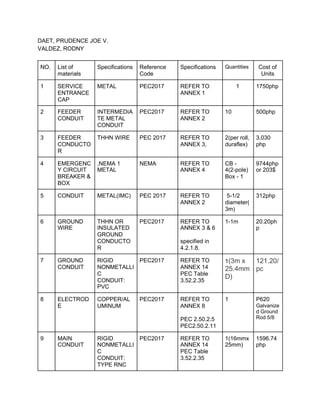
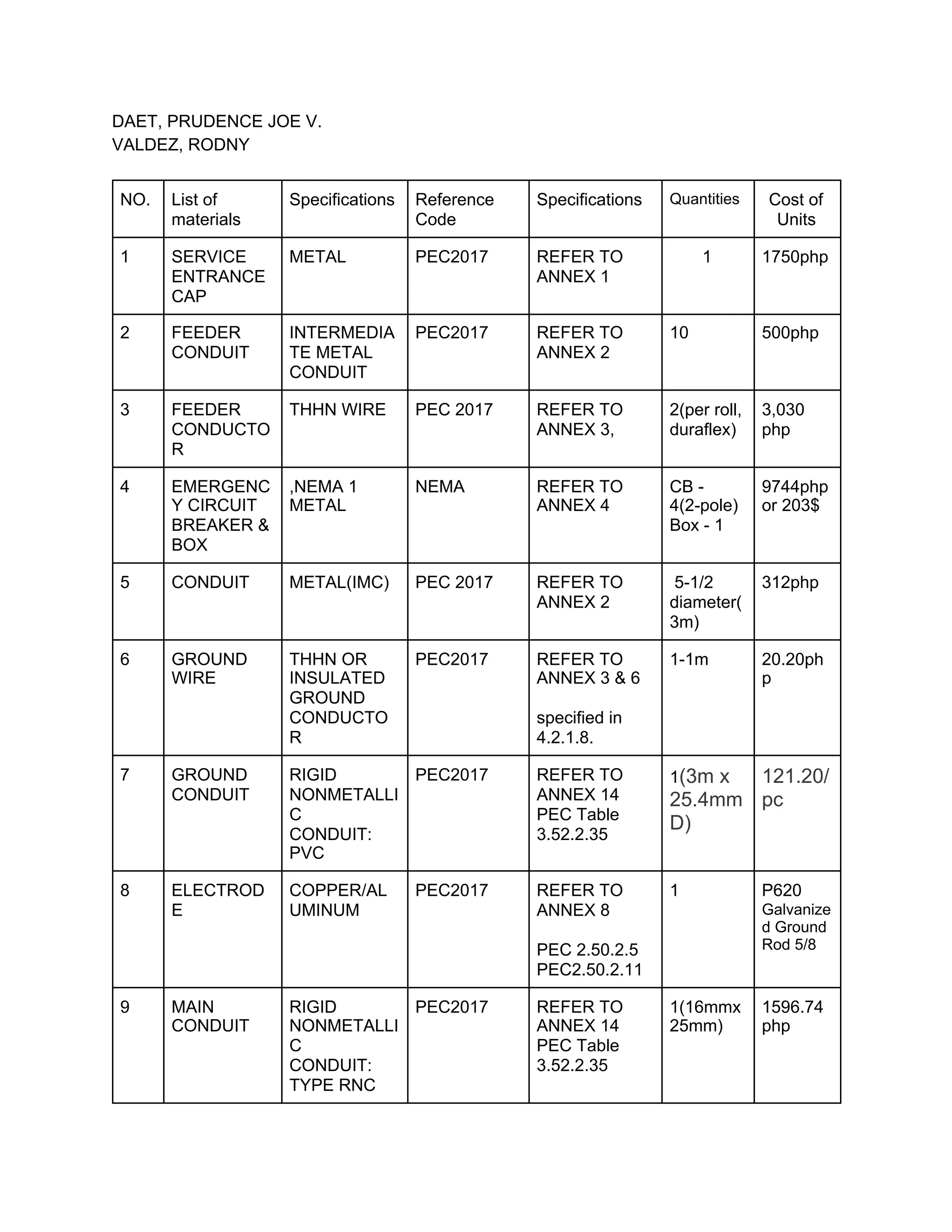
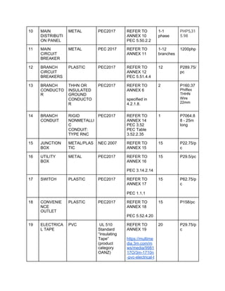
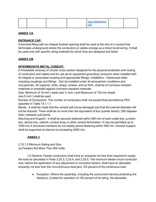
This document provides a list of materials and specifications for an electrical installation project. It includes 14 items with descriptions of materials like service entrance caps, feeder conduit, conductors, emergency circuit breakers, distribution panels, switches and more. Specifications are provided for proper installation and sizing according to standards like the Philippine Electrical Code (PEC) 2017. Total estimated cost is provided for each item and annexes provide additional details for specifications referenced.


