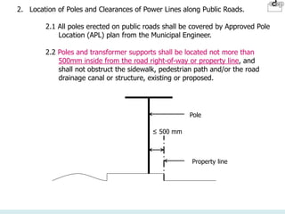
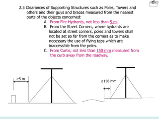
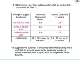
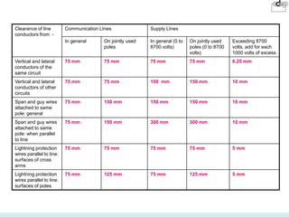
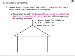
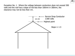
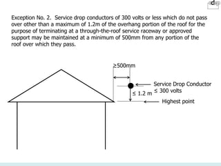
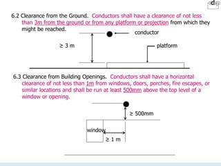
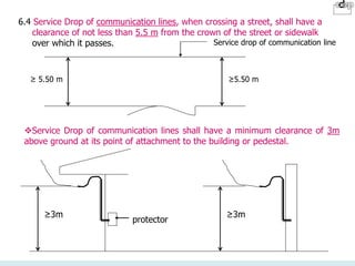
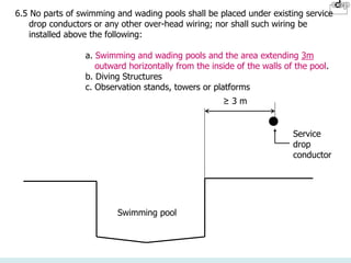
SlideShare a Scribd company logo
ELECTRICAL REGULATIONS
BY PD 1096
1. General Locational Requirements in Towns,
Subdivisions, Human Settlements, Industrial Estates
and the like.
Overhead transmission and/or distribution
lines/systems including transformers, poles, towers and
the like shall be located and installed following the
latest standards of design, construction and
maintenance but so as not to cause visual pollution and
in the interest of public safety, convenience, good
viewing and aesthetics, these may be located along
alleys or back streets.
2. Location of Poles and Clearances of Power Lines along Public Roads.
2.1 All poles erected on public roads shall be covered by Approved Pole
Location (APL) plan from the Municipal Engineer.
2.2 Poles and transformer supports shall be located not more than
500mm inside from the road right-of-way or property line, and
shall not obstruct the sidewalk, pedestrian path and/or the road
drainage canal or structure, existing or proposed.
≤ 500 mm
Property line
Pole
2.3 Primary lines shall have a minimum vertical clearance of 10 m
from the crown of the pavement when crossing the highway
and 7.5 m from the top of the shoulder or sidewalk when installed
along the side of the highway or street in a highly urbanized area.
≥10 m
≥7.5 m
2.4 Secondary, neutral and service lines shall have a minimum vertical
clearance of 7.5 m from the crown of the road pavement when
crossing the highway and from the top of the shoulder or sidewalk
when installed along the side of the highway or street in highly
urbanized area.
2.5 Clearances of Supporting Structures such as Poles, Towers and
others and their guys and braces measured from the nearest
parts of the objects concerned:
A. From Fire Hydrants, not less than 5 m.
B. From the Street Corners, where hydrants are
located at street corners, poles and towers shall
not be set so far from the corners as to make
necessary the use of flying taps which are
inaccessible from the poles.
C. From Curbs, not less than 150 mm measured from
the curb away from the roadway.
≥5 m
≥150 mm
3. Attachments on and Clearances from Buildings
3.1 Attachments for support of power lines and cables, transformers and other
equipment and/or communications lines installed on buildings shall be
covered by an Approved Attachment Plan from the local Building Official.
3.2 Where buildings exceed 15 m in height, overhead lines shall be arranged
where practicable so that a clear space or zone at least 2 m wide will be
left, either adjacent to the building or beginning not over 2.5 m from the
building, to facilitate the raising of ladders where necessary for fire
fighting.
2 - 2.5 m
Pole
≥ 15 m
4. Open Supply Conductors Attached to Buildings
Where the permanent attachment of open supply conductors of any class to
buildings is necessary for an entrance such conductors shall meet the following
requirements:
4.1 Conductors of more than 300 volts to ground shall not be carried along or
near the surface of the buildings unless they are guarded or made
inaccessible.
4.2 To promote safety to the general public and to employees not authorized
to approach conductors and other current-carrying parts of electric supply
lines, such parts shall be arranged so as to provide adequate clearance
from the ground or other space generally accessible, or shall be provided
with guards so as to isolate them effectively from accidental contact by
such persons.
4.3 Undergrounded metal-sheathed service cables, service conduits, metal
fixtures and similar noncurrent-carrying parts, if located in urban districts
and where liable to become charged to more than 300 volts to ground,
shall be isolated or guarded so as not to be exposed to accidental contact
by unauthorized persons. As an alternative to isolation or guarding,
noncurrent-carrying parts shall be solidly or effectively grounded.
4.4 Clearance of wires from building surface shall be not less than
those required Table II.
4.5 Supports over buildings. Service-drop conductors passing over a
roof shall be securely supported by substantial structures.
Where practicable, such supports shall be independent of the
building.
Voltage of Supply
Conductors
Horizontal
Clearance in
Meters
Vertical Clearance
in Meters
300 to 8,700 volts 1.0 2.5
8,700 to 15,000
volts
2.5 2.5
15,000 to 50,000
volts
3.0 3.0
> 50,000 volts 3.0 + 10 mm per Kv
in excess
3.0 + 10 mm per Kv
in excess
5. Conductors Passing By or Over Buildings
5.1 Minimum Clearances. Unguarded or accessible supply conductors
carrying voltages in excess of 300 volts may be run either beside
or over buildings. The vertical or horizontal clearance to any
building or its attachments (balconies, platforms, etc.) shall be as
listed below. The horizontal clearance governs above the roof
level to the point where the diagonal equals the vertical clearance
requirement. This rule should not be interpreted as restricting the
installation of a trolley contact conductor over the approximate
center line of the track it serves.
5.2 Guarding of Supply Conductors/Supply of Conductors of 300 volts
or more shall be properly guarded by grounded conduit, barriers,
or otherwise, under the following conditions:
1. Where the clearances set forth in Table II above cannot
be obtained.
2. Where such supply conductors are placed near enough to
windows, verandas, fire escapes, or other ordinarily
accessible places within the reach of persons.
5.3 Where the required clearances cannot be obtained, supply
conductors shall be of Grounded Metallic Shield, Jacketed Primary
Cables grouped or bundled and supported by grounded messenger
wires.
V-
≥V
Clearance of line
conductors from -
Communication LInes Supply LInes
In general On jointly used
poles
In general (0 to
8700 volts)
On jointly used
poles (0 to 8700
volts)
Exceeding 8700
volts, add for each
1000 volts of excess
Vertical and lateral
conductors of the
same circuit
75 mm 75 mm 75 mm 75 mm 6.25 mm
Vertical and lateral
conductors of other
circuits
75 mm 75 mm 150 mm 150 mm 10 mm
Span and guy wires
attached to same
pole: general
75 mm 150 mm 150 mm 150 mm 10 mm
Span and guy wires
attached to same
pole: when parallel
to line
75 mm 150 mm 300 mm 300 mm 10 mm
Lightning protection
wires parallel to line:
surfaces of cross
arms
75 mm 75 mm 75 mm 75 mm 5 mm
Lightning protection
wires parallel to line:
surfaces of poles
75 mm 125 mm 75 mm 125 mm 5 mm
6. Clearance of Service Drops
6.1 Service drop conductors shall not be readily accessible and when not in
excess of 600 volts, shall conform to the following:
a. Clearances over roof. Conductors shall have a clearance of not less
than 2.5m from the highest point of roofs over which they pass with
the following exceptions:
≥ 2.5 m
Highest point
Service Drop Conductor
< 600 volts
Exception No. 1. Where the voltage between conductors does not exceed 300
volts and the roof has a slope of not less than 100mm in 300mm, the
clearance may not be less than 1m.
≥1 m
Highest point
Service Drop Conductor
≤300 volts
Slope ≥ 1:3
Exception No. 2. Service drop conductors of 300 volts or less which do not pass
over other than a maximum of 1.2m of the overhang portion of the roof for the
purpose of terminating at a through-the-roof service raceway or approved
support may be maintained at a minimum of 500mm from any portion of the
roof over which they pass.
≤ 1.2 m
Highest point
Service Drop Conductor
≤ 300 volts
≥500mm
6.2 Clearance from the Ground. Conductors shall have a clearance of not less
than 3m from the ground or from any platform or projection from which they
might be reached.
conductor
platform
≥ 3 m
6.3 Clearance from Building Openings. Conductors shall have a horizontal
clearance of not less than 1m from windows, doors, porches, fire escapes, or
similar locations and shall be run at least 500mm above the top level of a
window or opening.
window
≥ 500mm
≥ 1 m
6.4 Service Drop of communication lines, when crossing a street, shall have a
clearance of not less than 5.5 m from the crown of the street or sidewalk
over which it passes.
≥ 5.50 m ≥5.50 m
Service drop of communication line
Service Drop of communication lines shall have a minimum clearance of 3m
above ground at its point of attachment to the building or pedestal.
≥3m
protector
≥3m
6.5 No parts of swimming and wading pools shall be placed under existing service
drop conductors or any other over-head wiring; nor shall such wiring be
installed above the following:
a. Swimming and wading pools and the area extending 3m
outward horizontally from the inside of the walls of the pool.
b. Diving Structures
c. Observation stands, towers or platforms
Swimming pool
Service
drop
conductor
≥ 3 m
7. Wiring Methods
Service entrance conductors extending along the exterior or entering
buildings or other structures shall be installed in rigid steel conduit or
asbestos cement conduit or concrete encased plastic conduit from point of
service drop to meter socket and from meter socket to the disconnecting
equipment. However, where the service entrance conductors are protected
by approved fuses or breakers at their outer ends (immediately after the
service drop or lateral) they may be installed in any of the recognized wiring
methods.
7.1 Abandoned Lines and/or portions of lines no longer required to provide
shall be removed.
7.2 Power or communication poles, lines, service drops and other line
equipment shall be free from any attachment for antennas, signs,
streamers and the like.
7.3 Metallic sheaths or jackets of overhead power or communication cables
shall be grounded at a point as close as possible to ground level
whenever such cables change from overhead to underground
installations.
8. Transformers
8.1 Oil-insulated Transformers Installed Outdoors. Combustible material,
combustible buildings and parts of buildings, fire escapes, door and
window openings shall be safeguarded from fires originating in oil-
insulated transformers installed on, attached to, or adjacent to a building
or combustible material. Space separations, fire-resistant barriers and
enclosures which confine the oil of a ruptured transformer tank are
recognized safeguards. One or more of these safeguards shall be applied
according to the degree of hazard involved in cases where the transformer
installation presents a fire hazard. Oil enclosures may consist of fire-
resistant dikes, curbed areas or basins, or trenches filled with coarse,
crushed stone. Oil enclosures shall be provided with trapped drains in
cases where the exposure and the quantity of oil involved are such that
removal of oil is important.
Trench all
around
Exterior Oil-insulated
Transformer
8.2 Dry-Type Transformers Installed Indoors. Transformers rated 112-1/2 KVA
or less shall have separation of at least 300mm from combustible material
unless separated there from by a fire-resistant heat-insulating barrier or
unless of a rating not exceeding 600 volts and completely enclosed except for
ventilating openings.
Dry-type transformer
112-1/2 Kva or less
≥ 300mm
Combustible Wall
8.3 Askarel-Insulated Transformers Installed Indoors. Askarel-insulated
transformers rated in excess of 25 KVA shall be furnished with a pressure
relief vent. Where installed in a poorly ventilated place they shall be
furnished with a means for absorbing any gases generated by arcing inside
the case, or the pressure relief vent shall be connected to a chimney or flue
which will carry such gases outside the building. Askarel-insulated
transformers rated more than 35,000 volts shall be installed in a vault.
Transformers of more than 112-1/2 KVA rating shall be installed in a transformer
room of fire-resistant construction unless they are constructed with Class B (80ºC
rise) or Class H (150ºC rise) insulation, and are separated from combustible
material not less than 1.85m horizontally and 3.7m vertically or are separated
there from by a fire-resistant heat-insulating barrier.
Transformers rated more than 35,000 volts shall be installed in a vault.
Dry-type transformer
112-1/2 Kva or less
≥ 1.85 m
Combustible
Wall
Combustible ceiling
≥ 3.70 m
vault
Transformer more
than 35,000 volts
8.4 Oil-Insulated Transformers Installed Indoors. Oil-insulated transformers shall
be installed in a vault constructed as specified in this Section except as follows:
1. NOT OVER 112-1/2KVA TOTAL CAPACITY. The provisions for transformer
vaults specified in Section 9.3 of this Rule apply except that the vault may
be constructed of reinforced concrete not less than 100mm thick.
2. NOT OVER 600 VOLTS. A vault is not required provided suitable
arrangements are made where necessary to prevent a transformer oil fire
igniting other materials, and the total transformer capacity in one location
does not exceed 10 KVA in a section of the building classified as
combustible, or 75 KVA where the surrounding structures is classified as
fire-resistant construction.
> 100mm thick reinforced
concrete vault
oil insulated transformer
< 112-1/2 KVa
8.5 Guarding. Transformers shall be guarded as follows:
1. MECHANICAL PROTECTION. Appropriate provisions shall be made
to minimize the possibility of damage to transformers from external
causes where the transformers are located exposed to physical
damage.
2. CASE OR ENCLOSURE. Dry-type transformers shall be provided with
a non-combustible moisture resistant case or enclosure which will
provide reasonable protection against accidental insertion of foreign
objects.
3. EXPOSED LIVE PARTS. The transformer installation shall conform
with the provisions for guarding of live parts in PEC Rule 1056.
4. VOLTAGE WARNING. The operating voltage of exposed live parts of
transformer installations shall be indicated by signs or visible
markings on the equipment or structures.
3. FURNACE TRANSFORMERS. Electric furnace transformers of a total rating
not exceeding 75 KVA may be installed without a vault in a building or room
of fire-resistant construction provided suitable arrangements are made to
prevent a transformer oil fire spreading to other combustible material.
4. DETACHED BUILDING. Transformers may be installed in a building which
does not conform with the provisions specified in this Code for transformer
vault, provided neither the building nor its contents present fire hazard to
any other building or property, and provided the building is used only in
supplying electric service and the interior is accessible only to qualified
persons.
9. Provisions for Transformer Vaults
9.1 New Building. New buildings requiring an expected load demand of
200KVA or above shall be provided with a transformer vault, except that
transformers may be mounted on poles or structures within the property if
enough space is available, provided that all clearances required can be
obtained and no troublesome contamination on insulators, bushings, etc.
can cause hazards and malfunctioning of the equipment.
150 mm for R.C
200 mm for Brick
300 mm for Load bearing CHB
200 Kva or more
Wall:
20 mm thick plaster
2-1/2 hours fire rating
Floor:
100mm thick
2-1/2 hours fire rating
9.2 Location. Transformer and transformer vaults shall be readily accessible to
qualified personnel for inspection and maintenance. Vaults shall be located
where they can be ventilated to the outside air without using flues or ducts
wherever such an arrangement is practicable.
9.3 Walls, Roof and Floor. The walls and roofs of vaults shall consist of reinforced
concrete not less than 150mm thick, masonry or brick not less than 200mm
thick, or 300mm load bearing hollow concrete blocks. The inside wall and roof
surface of vaults constructed of hollow concrete blocks shall have a coating of
cement or gypsum plaster not less than 20mm thick. The vault shall have a
concrete floor not less than 100mm thick. Building walls and floor which meet
these requirements may serve for the floor, roof and one or more walls of the
vaults. Other forms of fire-resistive construction are also acceptable provided
they have adequate structural strength for the conditions and a minimum fire
resistance of two and one half hours according to the approved Fire Test
Standard. The quality of the material used in the construction of the vault shall
be of the grade approved by the Building Official having jurisdiction.
9.4 Doorways. Any doorway leading from the vault into the building shall be
protected as follows:
1. TYPE OF DOOR. Each doorway shall be provided with a tight-fitting
door of a type approved for openings in such locations by the authority
enforcing this Code.
2. SILLS. A door sill or curb of sufficient height to confine within the
vault, the oil from the largest transformer shall be provided and in no
case shall the height be less than 100mm.
3. LOCKS. Entrance doors shall be equipped with locks, and doors shall
be kept locked, access being allowed only to qualified persons. Locks
and latches shall be so arranged that the door may be readily and
quickly opened from the inside.
10.Ventilation. Ventilation shall be adequate to prevent a transformer temperature
in excess of the prescribed values.
1. LOCATION. Ventilation openings shall be located as far away as
possible from doors, windows, fire escapes and combustible material.
2. ARRANGEMENT. Vaults ventilated by natural circulation of air may have
roughly half of the total area of openings required or ventilation in one or more
openings near the floor and the remainder in one or more openings in the roof
or in the sidewalls near the roof; or all of the area required for ventilation may
be provided in one or more openings in or near the roof.
3. SIZE. In the case of vaults ventilated to an outdoor area without using ducts or
flues the combined net area of all ventilating openings after deducting the area
occupied by screens, grating, or louvers, shall be not less than 0.006 sqmm per
KVA of transformer capacity in service, except that the net area shall be not
less than 0.1 sqm for any capacity under 50 KVA.
4. COVERING. Ventilation openings shall be covered with durable gratings,
screens, or louvers, according to the treatment requirement required in order to
avoid unsafe conditions.
5. DAMPERS. Where automatic dampers are used in the ventilation openings of
vaults containing oil-insulated transformers, the actuating device should be
made to function at a temperature resulting from fire and not a temperature
which might prevail as a result of an overheated transformer or bank of
transformers. Automatic dampers should be designed and constructed to
minimize the possibility of accidental closing.
6. DUCTS. Ventilating ducts shall be constructed of fire resistant material.
7. DRAINAGE. Where practicable, vaults containing more than 100KVA
transformer capacity shall be provided with a drain or other means which will
carry off any accumulation of oil or water in the vaults unless local conditions
make this impracticable.
8. WATER PIPES AND ACCESSORIES. Any pipe or duct system foreign to the
electrical installation should not enter or pass through a transformer vault.
Where the presence of such foreign system cannot be avoided, appurtenances
thereto which require maintenance at regular intervals shall not be located
inside the vault. Arrangements shall be made where necessary to avoid
possible trouble from compensation, leaks and breaks in such foreign system.
Piping or other facilities provided for fire protection or for water-cooled
transformers are not deemed to be foreign to the electrical installation.
11.Capacitors.
1. Application. This section applies to installation of capacitors on electric
circuits in or on buildings.
Exception No. 1. Capacitors that are components of other apparatus shall
conform to the requirements for such apparatus.
Exception No. 2. Capacitors in hazardous locations shall comply with
additional requirements in PEC Section 400-415.
2. Location. An installation of capacitors in which any single unit contains
more than three gallons of combustible liquid shall be in a vault conforming
to part C of PEC Section 319.
3. Mechanical Protection. Capacitors shall be protected from physical damage
by location or by suitable fences, barriers or other enclosures.
4. Cases and Supports. Capacitors shall be protected from physical damage by
location or by suitable fences, barriers or other enclosures.
5. Transformers Used with Capacitors. Transformers which are components of
capacitor installations and are used for the purpose of connecting the
capacitor to a power circuit shall be installed in accordance with PEC Section
319. The KVA rating shall not be less than 135 per cent of the capacitor
rating in Kva.
12.Emergency Systems
1. The provisions of this Section shall apply to the installation, operation and
maintenance of circuits, systems and equipment intended to supply
illumination and power in the event of failure of the normal supply or in the
event of accident to elements of a system supplying power and illumination
essential for safety to life and proper where such systems or circuits are
required by the Fire Code, or by any government agency having jurisdiction.
Emergency systems are generally installed in places of assembly where
artificial illumination is required, such as buildings subject to occupancy by
large numbers of persons, hotels, theaters, sports arenas, hospitals and similar
institutions. Emergency systems provide power for such functions as
refrigeration, operation of mechanical breathing apparatus, ventilation
essential to maintain life, illumination and power for hospital room, fire alarm
systems, fire pumps, industrial processes where current interruption would
produce serious hazards, public address systems and other similar functions.
2. All requirements of this Section shall apply to emergency systems.
3. All equipment for use on emergency systems shall be properly approved.
4. Tests and Maintenance
a. The authority having jurisdiction shall conduct or witness a test on the
complete system upon completion of installation, and periodically afterwards.
b. Systems shall be tested periodically in accordance with a schedule acceptable
to the authority having jurisdiction to assure that they are maintained in proper
operating condition.
c. Where the battery systems or unit equipment are involved, including
batteries used for starting or ignition in auxiliary engines, the authority having
jurisdiction shall require periodic maintenance.
d. A written record shall be kept of such tests and maintenance.
5. Emergency systems shall have adequate capacity and rating for the emergency
operation of all equipment connected to the system.
6. Current supply shall be such that in the event of failure of the normal supply to
or within the building or group of buildings concerned, emergency lighting or
emergency power, will be immediately available. The supply system for
emergency purposes may be composed one or more of the types of systems
covered in Section 12.7 to Section 12.10 of this Rule. Unit equipment in
accordance with Section 12.21 shall satisfy the applicable requirements of this
Section.
Consideration must be given to the type of service to be rendered; whether for
short duration, as for exit lights of a theater, or for long duration, as for
supplying emergency power and lighting during long periods of current failure
from trouble either inside or outside the buildings, as in the case of a hospital.
Assignment of degree of reliability of the recognized emergency supply system
depends upon the careful evaluation of the variables of each particular
installation.
7. A storage battery of suitable rating and capacity shall supply, by means of a
service installed according to Section 200 of the PEC and maintained at not
more than 90 per cent of system voltage, the total load of the circuits supplying
emergency lighting and emergency power for a period of at least ½ hour.
8. A generator set driven by some form of prime mover, with sufficient capacity
and proper rating to supply circuits carrying emergency lighting or lighting and
power, equipped with suitable means for automatically starting the prime mover
on failure of the normal service shall be provided. For hospitals, the transition-
time from instant of failure of the normal power source to the emergency
generator source shall not exceed ten seconds. (See Section 12.4)
9. There shall be two services, each in accordance with Section 200 of the PEC,
widely separated electrically and physically to minimize the possibility of
simultaneous interruption of power supply arising from an occurrence within
the building or group of buildings served.
10.Connections on the line side of the main service shall be sufficiently separated
from said main service to prevent simultaneous interruption of supply through
an occurrence within the building or group of buildings served.
11. The requirements of Section 12.5 and Section 12.6 also apply to installations
where the entire electrical load on a service or sub-service is arranged to be
supplied from a second source. Current supply from a standby power plant
shall satisfy the requirements of availability in Section 12.6.
12.Audible and visual signal devices shall be provided, where practicable, for the
following purposes:
a. To give warning of dearrangement of the emergency or auxiliary source.
b. To indicate that the battery or generator set is carrying a load.
c. To indicate when a battery charger is properly functioning.
13. Only appliances and lamps specified as required for emergency use shall be
supplied by emergency lighting circuits.
14. Emergency illumination shall be provided for all required exit lights and all
other lights specified as necessary for sufficient illumination.
Emergency lighting systems should be so designed and installed that the
failure of any individual lighting element, such as the burning out of a light
bulb, shall not leave any area in total darkness.
15.Branch circuits intended to supply emergency lighting shall be so installed as to
provide service immediately when the normal supply for lighting is interrupted.
Such installations shall provide either one of the following:
a. An emergency lighting supply, independent of the general lighting
system with provisions for automatically transferring to the emergency
lights by means of devices approved for the purpose upon the event of
failure of the general lighting system supply.
b. Two or more separate and complete systems with independent power
supply, each system providing sufficient current for emergency lighting
purposes. Unless both systems are used for regular lighting purposes
and are both lighted, means shall be provided for automatically
energizing either system upon failure of the other. Either or both
systems may be part of the general lighting system of the protected
occupancy if circuits supplying lights for emergency illumination are
installed in accordance with other Section of this Rule.
16. For branch circuits which supply equipment classed as emergency, there shall
be an emergency supply source to which the load will be transferred
automatically and immediately upon the failure of the normal supply.
17. Emergency circuit wiring shall be kept entirely independent of all other wiring and
equipment and shall not enter the same raceway, box or cabinet with other wiring
except:
a. In transfer switches, or
b. In exit or emergency lighting fixtures supplied from two (2) sources.
18. The switches installed in emergency lighting circuits shall be so arranged that only
authorized persons have control of emergency lighting, except:
a. Where two or more single throw switches are connected in parallel to
control a single circuit, at least one of those switches shall be accessible
only to authorized persons.
b. Additional switches which act only to put emergency lights into operation
but not to disconnect them may be permitted.
Switches connected in series and three- and four-way switches shall not be
allowed.
19. All manual switches for controlling emergency circuits shall be located at the most
accessible place to authorized persons responsible for their actuation. In places of
assembly, such as theaters, a switch for controlling emergency lighting systems
shall be located in the lobby or at a place conveniently accessible there from.
In no case shall a control switch for emergency lighting in a theater for motion
picture projection be placed in the projection booth or on the stage. However,
where multiple switches are provided, one such switch may be installed in such
locations and so arranged that it can energize but not disconnect for the circuit.
20. Lights on the exterior of the building which are not required for illumination
when there is sufficient daylight may be controlled by an automatic light
actuated device approved for the purpose.
21. In hospital corridors, switching arrangements to transfer corridor lighting in
patient areas of hospitals from overhead fixtures to fixtures designed to provide
night lighting maybe permitted, provided that the switching system is so
designed that switches can only select between two sets of fixtures but cannot
extinguish both sets at the same time.
22.The branch circuits over current devices in emergency circuits shall be
accessible to authorized persons only.
23. Where permitted by the authority having jurisdiction, in lieu of other methods
specified elsewhere in this Section, individual unit equipment for emergency
illumination shall consist of:
a. Battery
b. Battery charging means, when a storage battery is used
c. One or more lamps, and
d. A relaying device arranged to energize the lamps automatically upon
failure of the normal supply to the building
The batteries shall be of suitable rating and capacity to supply and maintain, at not
less than 90 per cent of rated lamp voltage, the total lamp load associated with the
unit for a period of at least ½ hour. Storage batteries, whether of the acid or alkali
type, shall be designed and constructed to meet the requirements of emergency
service. Lead-acid type storage batteries shall have transparent jars.
Unit equipment shall be permanently fixed in place and shall have all wiring to each
unit installed in accordance with the requirements of any of the wiring methods
discussed in Chapter II of the PEC. They shall not be connected by flexible cord. The
supply circuit between the unit equipment and the service, the feeders or the branch
circuit wiring shall be installed as required by Section 12.17. Emergency illumination
fixtures which obtain power from a unit equipment which are not part of the unit
equipment shall be wired to the unit equipment as required by Rule 5257 of the PEC
and in accordance with the one of the wiring methods described in Chapter II of the
PEC.
13. Effectivity
1. All primary and secondary supply lines already existing shall comply with the
provisions of this Rule within two (2) years from the effectivity of this Rule.
2. Transformers to be installed on, attached to, or in buildings shall comply with the
requirements of this Rule. Transformer installations already existing shall comply with
the requirements within two (2) years from the effectivity of this Rule.
3. Non-compliance with the provisions of this Rule shall be subject to the penal
provisions in Section 213 of PD 1096.

More Related Content

Similar to electrical regulation ppt 0123321123333333

Engineering Final Year Project Report on "Electrical Safety and Protection of...
Engineering Final Year Project Report on "Electrical Safety and Protection of...Engineering Final Year Project Report on "Electrical Safety and Protection of...
Engineering Final Year Project Report on "Electrical Safety and Protection of...
Pratap Bhunia
 
B service project 2
B service project 2B service project 2
B service project 2
- -
 
Maintenance of Track in Electrified Areas.pptx
Maintenance of Track in Electrified Areas.pptxMaintenance of Track in Electrified Areas.pptx
Maintenance of Track in Electrified Areas.pptx
PUJARI4
 
VG check list for S & T cable laying
VG  check list for S & T cable laying VG  check list for S & T cable laying
VG check list for S & T cable laying
Varadharajalu Gopal
 
Iec 62305 for lightning and surge protection follow in india nbc 2016 by bis(...
Iec 62305 for lightning and surge protection follow in india nbc 2016 by bis(...Iec 62305 for lightning and surge protection follow in india nbc 2016 by bis(...
Iec 62305 for lightning and surge protection follow in india nbc 2016 by bis(...
Mahesh Chandra Manav
 
Nexans high-voltage.pdf
Nexans high-voltage.pdfNexans high-voltage.pdf
Nexans high-voltage.pdf
prse
 
Wiring estimation costing and contracting suitable for diploma electrical eng...
Wiring estimation costing and contracting suitable for diploma electrical eng...Wiring estimation costing and contracting suitable for diploma electrical eng...
Wiring estimation costing and contracting suitable for diploma electrical eng...
Raghuvirsinh Parmar
 
Entership Presentation (1).pptx
Entership Presentation (1).pptxEntership Presentation (1).pptx
Entership Presentation (1).pptx
mebremezgebe
 
Modern substation design 2
Modern substation design 2Modern substation design 2
Modern substation design 2
rajesh18001 R
 
Modern substation design
Modern substation designModern substation design
Modern substation design
rajesh18001 R
 
Hospital wiring SYSTEM
Hospital wiring SYSTEMHospital wiring SYSTEM
Hospital wiring SYSTEM
AISWARYA TV
 
Project amrut presentation jmv lps
Project  amrut presentation jmv lpsProject  amrut presentation jmv lps
Project amrut presentation jmv lps
Mahesh Chandra Manav
 
report on electrical wiring
report on electrical wiringreport on electrical wiring
report on electrical wiring
Abhidada123
 
DOMESTIC WIRING
DOMESTIC WIRINGDOMESTIC WIRING
DOMESTIC WIRING
Sjcit
 
04-3-TS_Vol-II_,Sec-IV,_Pre_Comm_R1.pdf
04-3-TS_Vol-II_,Sec-IV,_Pre_Comm_R1.pdf04-3-TS_Vol-II_,Sec-IV,_Pre_Comm_R1.pdf
04-3-TS_Vol-II_,Sec-IV,_Pre_Comm_R1.pdf
Anonymouscj7JdRbDb
 
Current collction system.pptx
Current collction system.pptxCurrent collction system.pptx
Current collction system.pptx
ssuserca5764
 
Lec no. 01
Lec no. 01Lec no. 01
Lec no. 01
SalmanTariq82
 
Presentation indian railway electrical and s&amp;t 1
Presentation indian railway electrical and s&amp;t 1Presentation indian railway electrical and s&amp;t 1
Presentation indian railway electrical and s&amp;t 1
Mahesh Chandra Manav
 
Presentation indian railway electrical and s&amp;t 1
Presentation indian railway electrical and s&amp;t 1Presentation indian railway electrical and s&amp;t 1
Presentation indian railway electrical and s&amp;t 1
Mahesh Chandra Manav
 

Similar to electrical regulation ppt 0123321123333333 (20)

Engineering Final Year Project Report on "Electrical Safety and Protection of...
Engineering Final Year Project Report on "Electrical Safety and Protection of...Engineering Final Year Project Report on "Electrical Safety and Protection of...
Engineering Final Year Project Report on "Electrical Safety and Protection of...
 
B service project 2
B service project 2B service project 2
B service project 2
 
Maintenance of Track in Electrified Areas.pptx
Maintenance of Track in Electrified Areas.pptxMaintenance of Track in Electrified Areas.pptx
Maintenance of Track in Electrified Areas.pptx
 
VG check list for S & T cable laying
VG  check list for S & T cable laying VG  check list for S & T cable laying
VG check list for S & T cable laying
 
Iec 62305 for lightning and surge protection follow in india nbc 2016 by bis(...
Iec 62305 for lightning and surge protection follow in india nbc 2016 by bis(...Iec 62305 for lightning and surge protection follow in india nbc 2016 by bis(...
Iec 62305 for lightning and surge protection follow in india nbc 2016 by bis(...
 
Nexans high-voltage.pdf
Nexans high-voltage.pdfNexans high-voltage.pdf
Nexans high-voltage.pdf
 
Wiring estimation costing and contracting suitable for diploma electrical eng...
Wiring estimation costing and contracting suitable for diploma electrical eng...Wiring estimation costing and contracting suitable for diploma electrical eng...
Wiring estimation costing and contracting suitable for diploma electrical eng...
 
Entership Presentation (1).pptx
Entership Presentation (1).pptxEntership Presentation (1).pptx
Entership Presentation (1).pptx
 
Modern substation design 2
Modern substation design 2Modern substation design 2
Modern substation design 2
 
Modern substation design
Modern substation designModern substation design
Modern substation design
 
Hospital wiring SYSTEM
Hospital wiring SYSTEMHospital wiring SYSTEM
Hospital wiring SYSTEM
 
Project amrut presentation jmv lps
Project  amrut presentation jmv lpsProject  amrut presentation jmv lps
Project amrut presentation jmv lps
 
report on electrical wiring
report on electrical wiringreport on electrical wiring
report on electrical wiring
 
DOMESTIC WIRING
DOMESTIC WIRINGDOMESTIC WIRING
DOMESTIC WIRING
 
04-3-TS_Vol-II_,Sec-IV,_Pre_Comm_R1.pdf
04-3-TS_Vol-II_,Sec-IV,_Pre_Comm_R1.pdf04-3-TS_Vol-II_,Sec-IV,_Pre_Comm_R1.pdf
04-3-TS_Vol-II_,Sec-IV,_Pre_Comm_R1.pdf
 
Current collction system.pptx
Current collction system.pptxCurrent collction system.pptx
Current collction system.pptx
 
Lec no. 01
Lec no. 01Lec no. 01
Lec no. 01
 
tac spray rules
tac spray rulestac spray rules
tac spray rules
 
Presentation indian railway electrical and s&amp;t 1
Presentation indian railway electrical and s&amp;t 1Presentation indian railway electrical and s&amp;t 1
Presentation indian railway electrical and s&amp;t 1
 
Presentation indian railway electrical and s&amp;t 1
Presentation indian railway electrical and s&amp;t 1Presentation indian railway electrical and s&amp;t 1
Presentation indian railway electrical and s&amp;t 1
 

Recently uploaded

Standard Reomte Control Interface - Neometrix
Standard Reomte Control Interface - NeometrixStandard Reomte Control Interface - Neometrix
Standard Reomte Control Interface - Neometrix
Neometrix_Engineering_Pvt_Ltd
 
power quality voltage fluctuation UNIT - I.pptx
power quality voltage fluctuation UNIT - I.pptxpower quality voltage fluctuation UNIT - I.pptx
power quality voltage fluctuation UNIT - I.pptx
ViniHema
 
Danfoss NeoCharge Technology -A Revolution in 2024.pdf
Danfoss NeoCharge Technology -A Revolution in 2024.pdfDanfoss NeoCharge Technology -A Revolution in 2024.pdf
Danfoss NeoCharge Technology -A Revolution in 2024.pdf
NurvisNavarroSanchez
 
WATER CRISIS and its solutions-pptx 1234
WATER CRISIS and its solutions-pptx 1234WATER CRISIS and its solutions-pptx 1234
WATER CRISIS and its solutions-pptx 1234
AafreenAbuthahir2
 
ASME IX(9) 2007 Full Version .pdf
ASME IX(9)  2007 Full Version       .pdfASME IX(9)  2007 Full Version       .pdf
ASME IX(9) 2007 Full Version .pdf
AhmedHussein950959
 
Student information management system project report ii.pdf
Student information management system project report ii.pdfStudent information management system project report ii.pdf
Student information management system project report ii.pdf
Kamal Acharya
 
Sachpazis:Terzaghi Bearing Capacity Estimation in simple terms with Calculati...
Sachpazis:Terzaghi Bearing Capacity Estimation in simple terms with Calculati...Sachpazis:Terzaghi Bearing Capacity Estimation in simple terms with Calculati...
Sachpazis:Terzaghi Bearing Capacity Estimation in simple terms with Calculati...
Dr.Costas Sachpazis
 
Hall booking system project report .pdf
Hall booking system project report  .pdfHall booking system project report  .pdf
Hall booking system project report .pdf
Kamal Acharya
 
Cloud-Computing_CSE311_Computer-Networking CSE GUB BD - Shahidul.pptx
Cloud-Computing_CSE311_Computer-Networking CSE GUB BD - Shahidul.pptxCloud-Computing_CSE311_Computer-Networking CSE GUB BD - Shahidul.pptx
Cloud-Computing_CSE311_Computer-Networking CSE GUB BD - Shahidul.pptx
Md. Shahidul Islam Prodhan
 
NO1 Pandit Amil Baba In Bahawalpur, Sargodha, Sialkot, Sheikhupura, Rahim Yar...
NO1 Pandit Amil Baba In Bahawalpur, Sargodha, Sialkot, Sheikhupura, Rahim Yar...NO1 Pandit Amil Baba In Bahawalpur, Sargodha, Sialkot, Sheikhupura, Rahim Yar...
NO1 Pandit Amil Baba In Bahawalpur, Sargodha, Sialkot, Sheikhupura, Rahim Yar...
Amil baba
 
ENERGY STORAGE DEVICES INTRODUCTION UNIT-I
ENERGY STORAGE DEVICES  INTRODUCTION UNIT-IENERGY STORAGE DEVICES  INTRODUCTION UNIT-I
ENERGY STORAGE DEVICES INTRODUCTION UNIT-I
VigneshvaranMech
 
Digital Signal Processing Lecture notes n.pdf
Digital Signal Processing Lecture notes n.pdfDigital Signal Processing Lecture notes n.pdf
Digital Signal Processing Lecture notes n.pdf
AbrahamGadissa
 
Democratizing Fuzzing at Scale by Abhishek Arya
Democratizing Fuzzing at Scale by Abhishek AryaDemocratizing Fuzzing at Scale by Abhishek Arya
Democratizing Fuzzing at Scale by Abhishek Arya
abh.arya
 
A CASE STUDY ON ONLINE TICKET BOOKING SYSTEM PROJECT.pdf
A CASE STUDY ON ONLINE TICKET BOOKING SYSTEM PROJECT.pdfA CASE STUDY ON ONLINE TICKET BOOKING SYSTEM PROJECT.pdf
A CASE STUDY ON ONLINE TICKET BOOKING SYSTEM PROJECT.pdf
Kamal Acharya
 
Construction method of steel structure space frame .pptx
Construction method of steel structure space frame .pptxConstruction method of steel structure space frame .pptx
Construction method of steel structure space frame .pptx
wendy cai
 
weather web application report.pdf
weather web application report.pdfweather web application report.pdf
weather web application report.pdf
Pratik Pawar
 
Top 13 Famous Civil Engineering Scientist
Top 13 Famous Civil Engineering ScientistTop 13 Famous Civil Engineering Scientist
Top 13 Famous Civil Engineering Scientist
gettygaming1
 
Final project report on grocery store management system..pdf
Final project report on grocery store management system..pdfFinal project report on grocery store management system..pdf
Final project report on grocery store management system..pdf
Kamal Acharya
 
Courier management system project report.pdf
Courier management system project report.pdfCourier management system project report.pdf
Courier management system project report.pdf
Kamal Acharya
 
Introduction to Casting Processes in Manufacturing
Introduction to Casting Processes in ManufacturingIntroduction to Casting Processes in Manufacturing
Introduction to Casting Processes in Manufacturing
ssuser0811ec
 

Recently uploaded (20)

Standard Reomte Control Interface - Neometrix
Standard Reomte Control Interface - NeometrixStandard Reomte Control Interface - Neometrix
Standard Reomte Control Interface - Neometrix
 
power quality voltage fluctuation UNIT - I.pptx
power quality voltage fluctuation UNIT - I.pptxpower quality voltage fluctuation UNIT - I.pptx
power quality voltage fluctuation UNIT - I.pptx
 
Danfoss NeoCharge Technology -A Revolution in 2024.pdf
Danfoss NeoCharge Technology -A Revolution in 2024.pdfDanfoss NeoCharge Technology -A Revolution in 2024.pdf
Danfoss NeoCharge Technology -A Revolution in 2024.pdf
 
WATER CRISIS and its solutions-pptx 1234
WATER CRISIS and its solutions-pptx 1234WATER CRISIS and its solutions-pptx 1234
WATER CRISIS and its solutions-pptx 1234
 
ASME IX(9) 2007 Full Version .pdf
ASME IX(9)  2007 Full Version       .pdfASME IX(9)  2007 Full Version       .pdf
ASME IX(9) 2007 Full Version .pdf
 
Student information management system project report ii.pdf
Student information management system project report ii.pdfStudent information management system project report ii.pdf
Student information management system project report ii.pdf
 
Sachpazis:Terzaghi Bearing Capacity Estimation in simple terms with Calculati...
Sachpazis:Terzaghi Bearing Capacity Estimation in simple terms with Calculati...Sachpazis:Terzaghi Bearing Capacity Estimation in simple terms with Calculati...
Sachpazis:Terzaghi Bearing Capacity Estimation in simple terms with Calculati...
 
Hall booking system project report .pdf
Hall booking system project report  .pdfHall booking system project report  .pdf
Hall booking system project report .pdf
 
Cloud-Computing_CSE311_Computer-Networking CSE GUB BD - Shahidul.pptx
Cloud-Computing_CSE311_Computer-Networking CSE GUB BD - Shahidul.pptxCloud-Computing_CSE311_Computer-Networking CSE GUB BD - Shahidul.pptx
Cloud-Computing_CSE311_Computer-Networking CSE GUB BD - Shahidul.pptx
 
NO1 Pandit Amil Baba In Bahawalpur, Sargodha, Sialkot, Sheikhupura, Rahim Yar...
NO1 Pandit Amil Baba In Bahawalpur, Sargodha, Sialkot, Sheikhupura, Rahim Yar...NO1 Pandit Amil Baba In Bahawalpur, Sargodha, Sialkot, Sheikhupura, Rahim Yar...
NO1 Pandit Amil Baba In Bahawalpur, Sargodha, Sialkot, Sheikhupura, Rahim Yar...
 
ENERGY STORAGE DEVICES INTRODUCTION UNIT-I
ENERGY STORAGE DEVICES  INTRODUCTION UNIT-IENERGY STORAGE DEVICES  INTRODUCTION UNIT-I
ENERGY STORAGE DEVICES INTRODUCTION UNIT-I
 
Digital Signal Processing Lecture notes n.pdf
Digital Signal Processing Lecture notes n.pdfDigital Signal Processing Lecture notes n.pdf
Digital Signal Processing Lecture notes n.pdf
 
Democratizing Fuzzing at Scale by Abhishek Arya
Democratizing Fuzzing at Scale by Abhishek AryaDemocratizing Fuzzing at Scale by Abhishek Arya
Democratizing Fuzzing at Scale by Abhishek Arya
 
A CASE STUDY ON ONLINE TICKET BOOKING SYSTEM PROJECT.pdf
A CASE STUDY ON ONLINE TICKET BOOKING SYSTEM PROJECT.pdfA CASE STUDY ON ONLINE TICKET BOOKING SYSTEM PROJECT.pdf
A CASE STUDY ON ONLINE TICKET BOOKING SYSTEM PROJECT.pdf
 
Construction method of steel structure space frame .pptx
Construction method of steel structure space frame .pptxConstruction method of steel structure space frame .pptx
Construction method of steel structure space frame .pptx
 
weather web application report.pdf
weather web application report.pdfweather web application report.pdf
weather web application report.pdf
 
Top 13 Famous Civil Engineering Scientist
Top 13 Famous Civil Engineering ScientistTop 13 Famous Civil Engineering Scientist
Top 13 Famous Civil Engineering Scientist
 
Final project report on grocery store management system..pdf
Final project report on grocery store management system..pdfFinal project report on grocery store management system..pdf
Final project report on grocery store management system..pdf
 
Courier management system project report.pdf
Courier management system project report.pdfCourier management system project report.pdf
Courier management system project report.pdf
 
Introduction to Casting Processes in Manufacturing
Introduction to Casting Processes in ManufacturingIntroduction to Casting Processes in Manufacturing
Introduction to Casting Processes in Manufacturing
 

electrical regulation ppt 0123321123333333

  • 1. ELECTRICAL REGULATIONS BY PD 1096 1. General Locational Requirements in Towns, Subdivisions, Human Settlements, Industrial Estates and the like. Overhead transmission and/or distribution lines/systems including transformers, poles, towers and the like shall be located and installed following the latest standards of design, construction and maintenance but so as not to cause visual pollution and in the interest of public safety, convenience, good viewing and aesthetics, these may be located along alleys or back streets.
  • 2. 2. Location of Poles and Clearances of Power Lines along Public Roads. 2.1 All poles erected on public roads shall be covered by Approved Pole Location (APL) plan from the Municipal Engineer. 2.2 Poles and transformer supports shall be located not more than 500mm inside from the road right-of-way or property line, and shall not obstruct the sidewalk, pedestrian path and/or the road drainage canal or structure, existing or proposed. ≤ 500 mm Property line Pole
  • 3. 2.3 Primary lines shall have a minimum vertical clearance of 10 m from the crown of the pavement when crossing the highway and 7.5 m from the top of the shoulder or sidewalk when installed along the side of the highway or street in a highly urbanized area. ≥10 m ≥7.5 m 2.4 Secondary, neutral and service lines shall have a minimum vertical clearance of 7.5 m from the crown of the road pavement when crossing the highway and from the top of the shoulder or sidewalk when installed along the side of the highway or street in highly urbanized area.
  • 4. 2.5 Clearances of Supporting Structures such as Poles, Towers and others and their guys and braces measured from the nearest parts of the objects concerned: A. From Fire Hydrants, not less than 5 m. B. From the Street Corners, where hydrants are located at street corners, poles and towers shall not be set so far from the corners as to make necessary the use of flying taps which are inaccessible from the poles. C. From Curbs, not less than 150 mm measured from the curb away from the roadway. ≥5 m ≥150 mm
  • 5. 3. Attachments on and Clearances from Buildings 3.1 Attachments for support of power lines and cables, transformers and other equipment and/or communications lines installed on buildings shall be covered by an Approved Attachment Plan from the local Building Official. 3.2 Where buildings exceed 15 m in height, overhead lines shall be arranged where practicable so that a clear space or zone at least 2 m wide will be left, either adjacent to the building or beginning not over 2.5 m from the building, to facilitate the raising of ladders where necessary for fire fighting. 2 - 2.5 m Pole ≥ 15 m
  • 6. 4. Open Supply Conductors Attached to Buildings Where the permanent attachment of open supply conductors of any class to buildings is necessary for an entrance such conductors shall meet the following requirements: 4.1 Conductors of more than 300 volts to ground shall not be carried along or near the surface of the buildings unless they are guarded or made inaccessible. 4.2 To promote safety to the general public and to employees not authorized to approach conductors and other current-carrying parts of electric supply lines, such parts shall be arranged so as to provide adequate clearance from the ground or other space generally accessible, or shall be provided with guards so as to isolate them effectively from accidental contact by such persons. 4.3 Undergrounded metal-sheathed service cables, service conduits, metal fixtures and similar noncurrent-carrying parts, if located in urban districts and where liable to become charged to more than 300 volts to ground, shall be isolated or guarded so as not to be exposed to accidental contact by unauthorized persons. As an alternative to isolation or guarding, noncurrent-carrying parts shall be solidly or effectively grounded.
  • 7. 4.4 Clearance of wires from building surface shall be not less than those required Table II. 4.5 Supports over buildings. Service-drop conductors passing over a roof shall be securely supported by substantial structures. Where practicable, such supports shall be independent of the building. Voltage of Supply Conductors Horizontal Clearance in Meters Vertical Clearance in Meters 300 to 8,700 volts 1.0 2.5 8,700 to 15,000 volts 2.5 2.5 15,000 to 50,000 volts 3.0 3.0 > 50,000 volts 3.0 + 10 mm per Kv in excess 3.0 + 10 mm per Kv in excess
  • 8. 5. Conductors Passing By or Over Buildings 5.1 Minimum Clearances. Unguarded or accessible supply conductors carrying voltages in excess of 300 volts may be run either beside or over buildings. The vertical or horizontal clearance to any building or its attachments (balconies, platforms, etc.) shall be as listed below. The horizontal clearance governs above the roof level to the point where the diagonal equals the vertical clearance requirement. This rule should not be interpreted as restricting the installation of a trolley contact conductor over the approximate center line of the track it serves. 5.2 Guarding of Supply Conductors/Supply of Conductors of 300 volts or more shall be properly guarded by grounded conduit, barriers, or otherwise, under the following conditions: 1. Where the clearances set forth in Table II above cannot be obtained. 2. Where such supply conductors are placed near enough to windows, verandas, fire escapes, or other ordinarily accessible places within the reach of persons.
  • 9. 5.3 Where the required clearances cannot be obtained, supply conductors shall be of Grounded Metallic Shield, Jacketed Primary Cables grouped or bundled and supported by grounded messenger wires. V- ≥V
  • 10. Clearance of line conductors from - Communication LInes Supply LInes In general On jointly used poles In general (0 to 8700 volts) On jointly used poles (0 to 8700 volts) Exceeding 8700 volts, add for each 1000 volts of excess Vertical and lateral conductors of the same circuit 75 mm 75 mm 75 mm 75 mm 6.25 mm Vertical and lateral conductors of other circuits 75 mm 75 mm 150 mm 150 mm 10 mm Span and guy wires attached to same pole: general 75 mm 150 mm 150 mm 150 mm 10 mm Span and guy wires attached to same pole: when parallel to line 75 mm 150 mm 300 mm 300 mm 10 mm Lightning protection wires parallel to line: surfaces of cross arms 75 mm 75 mm 75 mm 75 mm 5 mm Lightning protection wires parallel to line: surfaces of poles 75 mm 125 mm 75 mm 125 mm 5 mm
  • 11. 6. Clearance of Service Drops 6.1 Service drop conductors shall not be readily accessible and when not in excess of 600 volts, shall conform to the following: a. Clearances over roof. Conductors shall have a clearance of not less than 2.5m from the highest point of roofs over which they pass with the following exceptions: ≥ 2.5 m Highest point Service Drop Conductor < 600 volts
  • 12. Exception No. 1. Where the voltage between conductors does not exceed 300 volts and the roof has a slope of not less than 100mm in 300mm, the clearance may not be less than 1m. ≥1 m Highest point Service Drop Conductor ≤300 volts Slope ≥ 1:3
  • 13. Exception No. 2. Service drop conductors of 300 volts or less which do not pass over other than a maximum of 1.2m of the overhang portion of the roof for the purpose of terminating at a through-the-roof service raceway or approved support may be maintained at a minimum of 500mm from any portion of the roof over which they pass. ≤ 1.2 m Highest point Service Drop Conductor ≤ 300 volts ≥500mm
  • 14. 6.2 Clearance from the Ground. Conductors shall have a clearance of not less than 3m from the ground or from any platform or projection from which they might be reached. conductor platform ≥ 3 m 6.3 Clearance from Building Openings. Conductors shall have a horizontal clearance of not less than 1m from windows, doors, porches, fire escapes, or similar locations and shall be run at least 500mm above the top level of a window or opening. window ≥ 500mm ≥ 1 m
  • 15. 6.4 Service Drop of communication lines, when crossing a street, shall have a clearance of not less than 5.5 m from the crown of the street or sidewalk over which it passes. ≥ 5.50 m ≥5.50 m Service drop of communication line Service Drop of communication lines shall have a minimum clearance of 3m above ground at its point of attachment to the building or pedestal. ≥3m protector ≥3m
  • 16. 6.5 No parts of swimming and wading pools shall be placed under existing service drop conductors or any other over-head wiring; nor shall such wiring be installed above the following: a. Swimming and wading pools and the area extending 3m outward horizontally from the inside of the walls of the pool. b. Diving Structures c. Observation stands, towers or platforms Swimming pool Service drop conductor ≥ 3 m
  • 17. 7. Wiring Methods Service entrance conductors extending along the exterior or entering buildings or other structures shall be installed in rigid steel conduit or asbestos cement conduit or concrete encased plastic conduit from point of service drop to meter socket and from meter socket to the disconnecting equipment. However, where the service entrance conductors are protected by approved fuses or breakers at their outer ends (immediately after the service drop or lateral) they may be installed in any of the recognized wiring methods. 7.1 Abandoned Lines and/or portions of lines no longer required to provide shall be removed. 7.2 Power or communication poles, lines, service drops and other line equipment shall be free from any attachment for antennas, signs, streamers and the like. 7.3 Metallic sheaths or jackets of overhead power or communication cables shall be grounded at a point as close as possible to ground level whenever such cables change from overhead to underground installations.
  • 18. 8. Transformers 8.1 Oil-insulated Transformers Installed Outdoors. Combustible material, combustible buildings and parts of buildings, fire escapes, door and window openings shall be safeguarded from fires originating in oil- insulated transformers installed on, attached to, or adjacent to a building or combustible material. Space separations, fire-resistant barriers and enclosures which confine the oil of a ruptured transformer tank are recognized safeguards. One or more of these safeguards shall be applied according to the degree of hazard involved in cases where the transformer installation presents a fire hazard. Oil enclosures may consist of fire- resistant dikes, curbed areas or basins, or trenches filled with coarse, crushed stone. Oil enclosures shall be provided with trapped drains in cases where the exposure and the quantity of oil involved are such that removal of oil is important. Trench all around Exterior Oil-insulated Transformer
  • 19. 8.2 Dry-Type Transformers Installed Indoors. Transformers rated 112-1/2 KVA or less shall have separation of at least 300mm from combustible material unless separated there from by a fire-resistant heat-insulating barrier or unless of a rating not exceeding 600 volts and completely enclosed except for ventilating openings. Dry-type transformer 112-1/2 Kva or less ≥ 300mm Combustible Wall
  • 20. 8.3 Askarel-Insulated Transformers Installed Indoors. Askarel-insulated transformers rated in excess of 25 KVA shall be furnished with a pressure relief vent. Where installed in a poorly ventilated place they shall be furnished with a means for absorbing any gases generated by arcing inside the case, or the pressure relief vent shall be connected to a chimney or flue which will carry such gases outside the building. Askarel-insulated transformers rated more than 35,000 volts shall be installed in a vault. Transformers of more than 112-1/2 KVA rating shall be installed in a transformer room of fire-resistant construction unless they are constructed with Class B (80ºC rise) or Class H (150ºC rise) insulation, and are separated from combustible material not less than 1.85m horizontally and 3.7m vertically or are separated there from by a fire-resistant heat-insulating barrier. Transformers rated more than 35,000 volts shall be installed in a vault. Dry-type transformer 112-1/2 Kva or less ≥ 1.85 m Combustible Wall Combustible ceiling ≥ 3.70 m vault Transformer more than 35,000 volts
  • 21. 8.4 Oil-Insulated Transformers Installed Indoors. Oil-insulated transformers shall be installed in a vault constructed as specified in this Section except as follows: 1. NOT OVER 112-1/2KVA TOTAL CAPACITY. The provisions for transformer vaults specified in Section 9.3 of this Rule apply except that the vault may be constructed of reinforced concrete not less than 100mm thick. 2. NOT OVER 600 VOLTS. A vault is not required provided suitable arrangements are made where necessary to prevent a transformer oil fire igniting other materials, and the total transformer capacity in one location does not exceed 10 KVA in a section of the building classified as combustible, or 75 KVA where the surrounding structures is classified as fire-resistant construction. > 100mm thick reinforced concrete vault oil insulated transformer < 112-1/2 KVa
  • 22. 8.5 Guarding. Transformers shall be guarded as follows: 1. MECHANICAL PROTECTION. Appropriate provisions shall be made to minimize the possibility of damage to transformers from external causes where the transformers are located exposed to physical damage. 2. CASE OR ENCLOSURE. Dry-type transformers shall be provided with a non-combustible moisture resistant case or enclosure which will provide reasonable protection against accidental insertion of foreign objects. 3. EXPOSED LIVE PARTS. The transformer installation shall conform with the provisions for guarding of live parts in PEC Rule 1056. 4. VOLTAGE WARNING. The operating voltage of exposed live parts of transformer installations shall be indicated by signs or visible markings on the equipment or structures. 3. FURNACE TRANSFORMERS. Electric furnace transformers of a total rating not exceeding 75 KVA may be installed without a vault in a building or room of fire-resistant construction provided suitable arrangements are made to prevent a transformer oil fire spreading to other combustible material. 4. DETACHED BUILDING. Transformers may be installed in a building which does not conform with the provisions specified in this Code for transformer vault, provided neither the building nor its contents present fire hazard to any other building or property, and provided the building is used only in supplying electric service and the interior is accessible only to qualified persons.
  • 23. 9. Provisions for Transformer Vaults 9.1 New Building. New buildings requiring an expected load demand of 200KVA or above shall be provided with a transformer vault, except that transformers may be mounted on poles or structures within the property if enough space is available, provided that all clearances required can be obtained and no troublesome contamination on insulators, bushings, etc. can cause hazards and malfunctioning of the equipment. 150 mm for R.C 200 mm for Brick 300 mm for Load bearing CHB 200 Kva or more Wall: 20 mm thick plaster 2-1/2 hours fire rating Floor: 100mm thick 2-1/2 hours fire rating
  • 24. 9.2 Location. Transformer and transformer vaults shall be readily accessible to qualified personnel for inspection and maintenance. Vaults shall be located where they can be ventilated to the outside air without using flues or ducts wherever such an arrangement is practicable. 9.3 Walls, Roof and Floor. The walls and roofs of vaults shall consist of reinforced concrete not less than 150mm thick, masonry or brick not less than 200mm thick, or 300mm load bearing hollow concrete blocks. The inside wall and roof surface of vaults constructed of hollow concrete blocks shall have a coating of cement or gypsum plaster not less than 20mm thick. The vault shall have a concrete floor not less than 100mm thick. Building walls and floor which meet these requirements may serve for the floor, roof and one or more walls of the vaults. Other forms of fire-resistive construction are also acceptable provided they have adequate structural strength for the conditions and a minimum fire resistance of two and one half hours according to the approved Fire Test Standard. The quality of the material used in the construction of the vault shall be of the grade approved by the Building Official having jurisdiction.
  • 25. 9.4 Doorways. Any doorway leading from the vault into the building shall be protected as follows: 1. TYPE OF DOOR. Each doorway shall be provided with a tight-fitting door of a type approved for openings in such locations by the authority enforcing this Code. 2. SILLS. A door sill or curb of sufficient height to confine within the vault, the oil from the largest transformer shall be provided and in no case shall the height be less than 100mm. 3. LOCKS. Entrance doors shall be equipped with locks, and doors shall be kept locked, access being allowed only to qualified persons. Locks and latches shall be so arranged that the door may be readily and quickly opened from the inside. 10.Ventilation. Ventilation shall be adequate to prevent a transformer temperature in excess of the prescribed values. 1. LOCATION. Ventilation openings shall be located as far away as possible from doors, windows, fire escapes and combustible material.
  • 26. 2. ARRANGEMENT. Vaults ventilated by natural circulation of air may have roughly half of the total area of openings required or ventilation in one or more openings near the floor and the remainder in one or more openings in the roof or in the sidewalls near the roof; or all of the area required for ventilation may be provided in one or more openings in or near the roof. 3. SIZE. In the case of vaults ventilated to an outdoor area without using ducts or flues the combined net area of all ventilating openings after deducting the area occupied by screens, grating, or louvers, shall be not less than 0.006 sqmm per KVA of transformer capacity in service, except that the net area shall be not less than 0.1 sqm for any capacity under 50 KVA. 4. COVERING. Ventilation openings shall be covered with durable gratings, screens, or louvers, according to the treatment requirement required in order to avoid unsafe conditions. 5. DAMPERS. Where automatic dampers are used in the ventilation openings of vaults containing oil-insulated transformers, the actuating device should be made to function at a temperature resulting from fire and not a temperature which might prevail as a result of an overheated transformer or bank of transformers. Automatic dampers should be designed and constructed to minimize the possibility of accidental closing.
  • 27. 6. DUCTS. Ventilating ducts shall be constructed of fire resistant material. 7. DRAINAGE. Where practicable, vaults containing more than 100KVA transformer capacity shall be provided with a drain or other means which will carry off any accumulation of oil or water in the vaults unless local conditions make this impracticable. 8. WATER PIPES AND ACCESSORIES. Any pipe or duct system foreign to the electrical installation should not enter or pass through a transformer vault. Where the presence of such foreign system cannot be avoided, appurtenances thereto which require maintenance at regular intervals shall not be located inside the vault. Arrangements shall be made where necessary to avoid possible trouble from compensation, leaks and breaks in such foreign system. Piping or other facilities provided for fire protection or for water-cooled transformers are not deemed to be foreign to the electrical installation.
  • 28. 11.Capacitors. 1. Application. This section applies to installation of capacitors on electric circuits in or on buildings. Exception No. 1. Capacitors that are components of other apparatus shall conform to the requirements for such apparatus. Exception No. 2. Capacitors in hazardous locations shall comply with additional requirements in PEC Section 400-415. 2. Location. An installation of capacitors in which any single unit contains more than three gallons of combustible liquid shall be in a vault conforming to part C of PEC Section 319. 3. Mechanical Protection. Capacitors shall be protected from physical damage by location or by suitable fences, barriers or other enclosures. 4. Cases and Supports. Capacitors shall be protected from physical damage by location or by suitable fences, barriers or other enclosures. 5. Transformers Used with Capacitors. Transformers which are components of capacitor installations and are used for the purpose of connecting the capacitor to a power circuit shall be installed in accordance with PEC Section 319. The KVA rating shall not be less than 135 per cent of the capacitor rating in Kva.
  • 29. 12.Emergency Systems 1. The provisions of this Section shall apply to the installation, operation and maintenance of circuits, systems and equipment intended to supply illumination and power in the event of failure of the normal supply or in the event of accident to elements of a system supplying power and illumination essential for safety to life and proper where such systems or circuits are required by the Fire Code, or by any government agency having jurisdiction. Emergency systems are generally installed in places of assembly where artificial illumination is required, such as buildings subject to occupancy by large numbers of persons, hotels, theaters, sports arenas, hospitals and similar institutions. Emergency systems provide power for such functions as refrigeration, operation of mechanical breathing apparatus, ventilation essential to maintain life, illumination and power for hospital room, fire alarm systems, fire pumps, industrial processes where current interruption would produce serious hazards, public address systems and other similar functions. 2. All requirements of this Section shall apply to emergency systems. 3. All equipment for use on emergency systems shall be properly approved.
  • 30. 4. Tests and Maintenance a. The authority having jurisdiction shall conduct or witness a test on the complete system upon completion of installation, and periodically afterwards. b. Systems shall be tested periodically in accordance with a schedule acceptable to the authority having jurisdiction to assure that they are maintained in proper operating condition. c. Where the battery systems or unit equipment are involved, including batteries used for starting or ignition in auxiliary engines, the authority having jurisdiction shall require periodic maintenance. d. A written record shall be kept of such tests and maintenance. 5. Emergency systems shall have adequate capacity and rating for the emergency operation of all equipment connected to the system.
  • 31. 6. Current supply shall be such that in the event of failure of the normal supply to or within the building or group of buildings concerned, emergency lighting or emergency power, will be immediately available. The supply system for emergency purposes may be composed one or more of the types of systems covered in Section 12.7 to Section 12.10 of this Rule. Unit equipment in accordance with Section 12.21 shall satisfy the applicable requirements of this Section. Consideration must be given to the type of service to be rendered; whether for short duration, as for exit lights of a theater, or for long duration, as for supplying emergency power and lighting during long periods of current failure from trouble either inside or outside the buildings, as in the case of a hospital. Assignment of degree of reliability of the recognized emergency supply system depends upon the careful evaluation of the variables of each particular installation. 7. A storage battery of suitable rating and capacity shall supply, by means of a service installed according to Section 200 of the PEC and maintained at not more than 90 per cent of system voltage, the total load of the circuits supplying emergency lighting and emergency power for a period of at least ½ hour.
  • 32. 8. A generator set driven by some form of prime mover, with sufficient capacity and proper rating to supply circuits carrying emergency lighting or lighting and power, equipped with suitable means for automatically starting the prime mover on failure of the normal service shall be provided. For hospitals, the transition- time from instant of failure of the normal power source to the emergency generator source shall not exceed ten seconds. (See Section 12.4) 9. There shall be two services, each in accordance with Section 200 of the PEC, widely separated electrically and physically to minimize the possibility of simultaneous interruption of power supply arising from an occurrence within the building or group of buildings served. 10.Connections on the line side of the main service shall be sufficiently separated from said main service to prevent simultaneous interruption of supply through an occurrence within the building or group of buildings served. 11. The requirements of Section 12.5 and Section 12.6 also apply to installations where the entire electrical load on a service or sub-service is arranged to be supplied from a second source. Current supply from a standby power plant shall satisfy the requirements of availability in Section 12.6.
  • 33. 12.Audible and visual signal devices shall be provided, where practicable, for the following purposes: a. To give warning of dearrangement of the emergency or auxiliary source. b. To indicate that the battery or generator set is carrying a load. c. To indicate when a battery charger is properly functioning. 13. Only appliances and lamps specified as required for emergency use shall be supplied by emergency lighting circuits. 14. Emergency illumination shall be provided for all required exit lights and all other lights specified as necessary for sufficient illumination. Emergency lighting systems should be so designed and installed that the failure of any individual lighting element, such as the burning out of a light bulb, shall not leave any area in total darkness.
  • 34. 15.Branch circuits intended to supply emergency lighting shall be so installed as to provide service immediately when the normal supply for lighting is interrupted. Such installations shall provide either one of the following: a. An emergency lighting supply, independent of the general lighting system with provisions for automatically transferring to the emergency lights by means of devices approved for the purpose upon the event of failure of the general lighting system supply. b. Two or more separate and complete systems with independent power supply, each system providing sufficient current for emergency lighting purposes. Unless both systems are used for regular lighting purposes and are both lighted, means shall be provided for automatically energizing either system upon failure of the other. Either or both systems may be part of the general lighting system of the protected occupancy if circuits supplying lights for emergency illumination are installed in accordance with other Section of this Rule. 16. For branch circuits which supply equipment classed as emergency, there shall be an emergency supply source to which the load will be transferred automatically and immediately upon the failure of the normal supply.
  • 35. 17. Emergency circuit wiring shall be kept entirely independent of all other wiring and equipment and shall not enter the same raceway, box or cabinet with other wiring except: a. In transfer switches, or b. In exit or emergency lighting fixtures supplied from two (2) sources. 18. The switches installed in emergency lighting circuits shall be so arranged that only authorized persons have control of emergency lighting, except: a. Where two or more single throw switches are connected in parallel to control a single circuit, at least one of those switches shall be accessible only to authorized persons. b. Additional switches which act only to put emergency lights into operation but not to disconnect them may be permitted. Switches connected in series and three- and four-way switches shall not be allowed. 19. All manual switches for controlling emergency circuits shall be located at the most accessible place to authorized persons responsible for their actuation. In places of assembly, such as theaters, a switch for controlling emergency lighting systems shall be located in the lobby or at a place conveniently accessible there from. In no case shall a control switch for emergency lighting in a theater for motion picture projection be placed in the projection booth or on the stage. However, where multiple switches are provided, one such switch may be installed in such locations and so arranged that it can energize but not disconnect for the circuit.
  • 36. 20. Lights on the exterior of the building which are not required for illumination when there is sufficient daylight may be controlled by an automatic light actuated device approved for the purpose. 21. In hospital corridors, switching arrangements to transfer corridor lighting in patient areas of hospitals from overhead fixtures to fixtures designed to provide night lighting maybe permitted, provided that the switching system is so designed that switches can only select between two sets of fixtures but cannot extinguish both sets at the same time. 22.The branch circuits over current devices in emergency circuits shall be accessible to authorized persons only. 23. Where permitted by the authority having jurisdiction, in lieu of other methods specified elsewhere in this Section, individual unit equipment for emergency illumination shall consist of: a. Battery b. Battery charging means, when a storage battery is used c. One or more lamps, and d. A relaying device arranged to energize the lamps automatically upon failure of the normal supply to the building
  • 37. The batteries shall be of suitable rating and capacity to supply and maintain, at not less than 90 per cent of rated lamp voltage, the total lamp load associated with the unit for a period of at least ½ hour. Storage batteries, whether of the acid or alkali type, shall be designed and constructed to meet the requirements of emergency service. Lead-acid type storage batteries shall have transparent jars. Unit equipment shall be permanently fixed in place and shall have all wiring to each unit installed in accordance with the requirements of any of the wiring methods discussed in Chapter II of the PEC. They shall not be connected by flexible cord. The supply circuit between the unit equipment and the service, the feeders or the branch circuit wiring shall be installed as required by Section 12.17. Emergency illumination fixtures which obtain power from a unit equipment which are not part of the unit equipment shall be wired to the unit equipment as required by Rule 5257 of the PEC and in accordance with the one of the wiring methods described in Chapter II of the PEC. 13. Effectivity 1. All primary and secondary supply lines already existing shall comply with the provisions of this Rule within two (2) years from the effectivity of this Rule. 2. Transformers to be installed on, attached to, or in buildings shall comply with the requirements of this Rule. Transformer installations already existing shall comply with the requirements within two (2) years from the effectivity of this Rule. 3. Non-compliance with the provisions of this Rule shall be subject to the penal provisions in Section 213 of PD 1096.