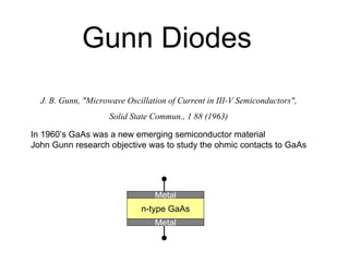
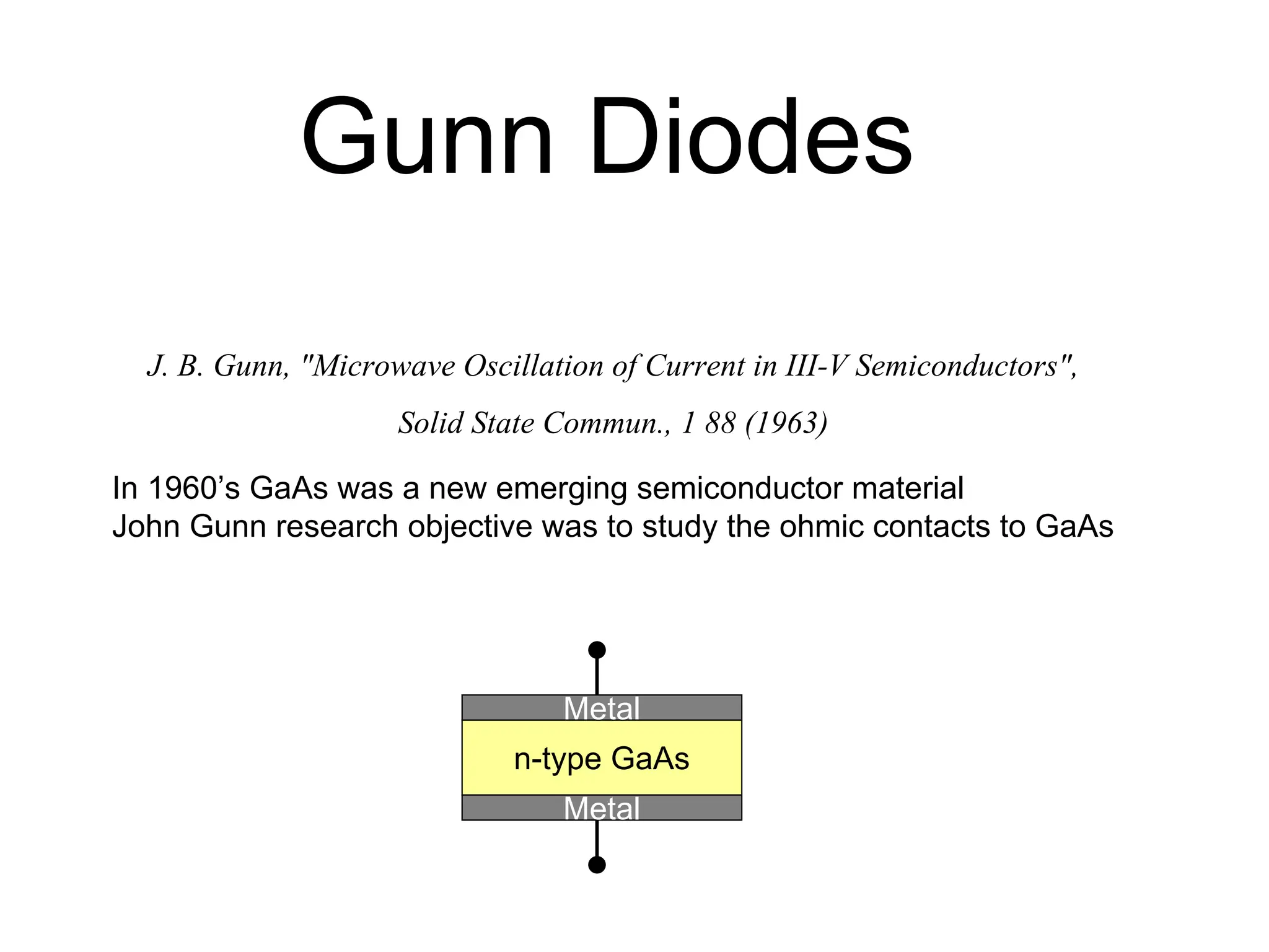
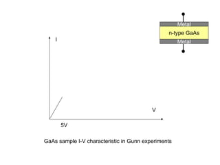
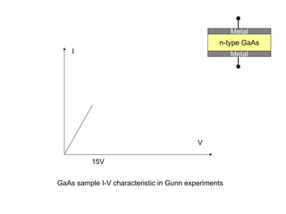
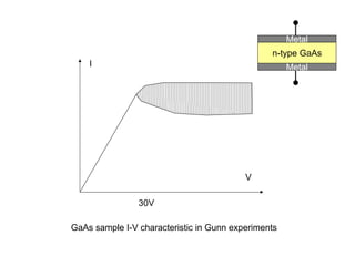
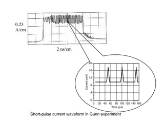
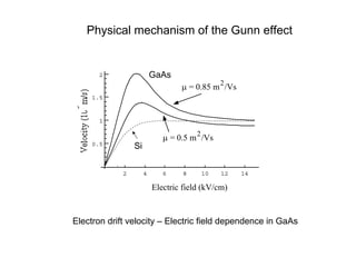
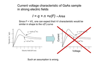
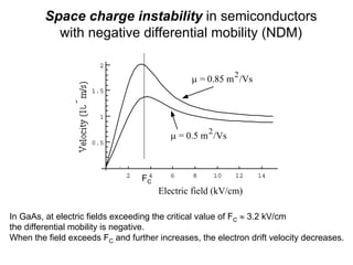
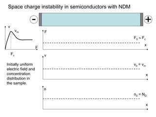
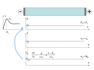
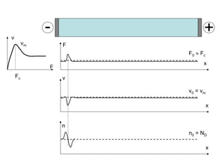
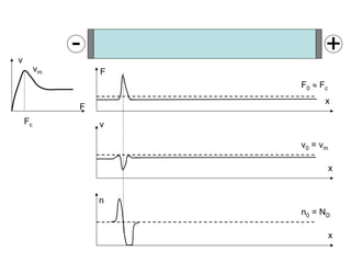
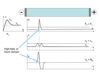
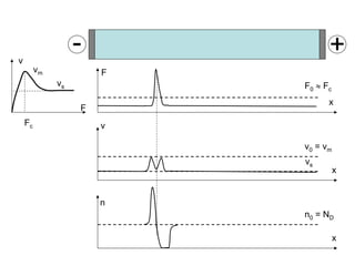
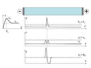
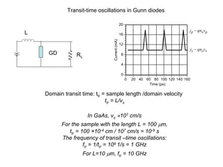
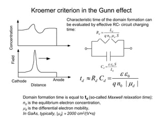
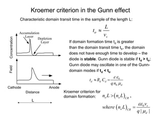
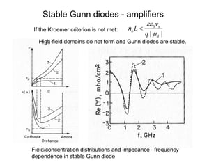
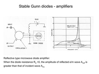
J. B. Gunn, "Microwave Oscillation of Current in III-V Semiconductors",
Solid State Commun., 1 88 (1963)
Gunn Diodes
n-type GaAs
Metal
Metal
In 1960’s GaAs was a new emerging semiconductor material
John Gunn research objective was to study the ohmic contacts to GaAs
V
I
GaAs sample I-V characteristic in Gunn experiments
n-type GaAs
Metal
Metal
5V
V
I
GaAs sample I-V characteristic in Gunn experiments
n-type GaAs
Metal
Metal
15V
V
I
GaAs sample I-V characteristic in Gunn experiments
30V
n-type GaAs
Metal
Metal
.
0
4
8
12
16
20
0 20 40 60 80 100 120 140 160
Current
(mA)
Time (ps)
js = qnovs
jp = qnovp
Short-pulse current waveform in Gunn experiment
Electron drift velocity – Electric field dependence in GaAs
2 4 6 8 10 12 14
0.5
1
1.5
2
Electric field (kV/cm)
μ = 0.85 m2
/Vs
μ = 0.5 m
2
/Vs
Physical mechanism of the Gunn effect
Si
GaAs
Such an assumption is wrong.
2 4 6 8 10 12 14
0.5
1
1.5
2
Electric field (kV/cm)
μ = 0.85 m
2
/Vs
μ = 0.5 m2
/Vs
Current voltage characteristic of GaAs sample
in strong electric fields
I = q × n ×v(F) × Area
Since F = V/L, one can expect that I-V characteristic would be
similar in shape to the v(F) curve
2 4 6 8 10 12 14
0.5
1
1.5
2
Electric field (kV/cm)
μ = 0.85 m
2
/Vs
μ = 0.5 m2
/Vs
Current
Voltage
2 4 6 8 10 12 14
0.5
1
1.5
2
Electric field (kV/cm)
μ = 0.85 m
2
/Vs
μ = 0.5 m
2
/Vs
Space charge instability in semiconductors
with negative differential mobility (NDM)
FC
In GaAs, at electric fields exceeding the critical value of FC ≈ 3.2 kV/cm
the differential mobility is negative.
When the field exceeds FC and further increases, the electron drift velocity decreases.
x
x
F0 ≈ Fc
v0 = vm
x
n0 = ND
F
v
Fc
vm
- +
F
v
n
Space charge instability in semiconductors with NDM
Initially uniform
electric field and
concentration
distribution in
the sample.
x
F0 ≈ Fc
F
v
Fc
vm
- +
F
x
v0 = vm
v
x
n0 = ND
n
0 0
D
F n N
q
x
ρ
ε ε ε ε
∂ −
=− =
∂
x
F
x
v
F0 ≈ Fc
v0 = vm
x
n
n0 = ND
F
v
Fc
vm
- +
x
F
x
v
F0 ≈ Fc
v0 = vm
x
n
n0 = ND
F
v
Fc
vm
- +
x
F
x
v
F0 ≈ Fc
v0 = vm
x
n
n0 = ND
F
v
Fc
vm
- +
vs
vs
High-field, or
Gunn domain
x
F
x
v
F0 ≈ Fc
v0 = vm
x
n
n0 = ND
F
v
Fc
vm
- +
vs
vs
x
F
x
v
F0 ≈ Fc
v0 = vm
x
n
n0 = ND
F
v
Fc
vm
- +
vs
vs
x
F
v
F0 ≈ Fc
F
v
Fc
vm
- +
vs
Current – time dependence in the sample with high-filed domain
Current at the device electrodes:
IV= q n vs
When the domain is moving between the cathode and anode:
F
v
Fc
vm
- +
vs
Current – time dependence in the sample with high-filed domain
Current at the device electrodes:
Im = q n vm
When the domain dissipates in the anode and new domain did not form yet:
x
x
F0 ≈ Fc
v0 = vm
F
v
v
Fc
vm
vs
Current – time dependence in the sample with high-filed domain
Im = q n vm
.
0
4
8
12
16
20
0 20 40 60 80 100 120 140 160
Current
(mA)
Time (ps)
js = qnovs
jp = qnovp
IV = q n vs
Transit-time oscillations in Gunn diodes
.
0
4
8
12
16
20
0 20 40 60 80 100 120 140 160
Current
(mA)
Time (ps)
js = qnovs
jp = qnovp
GD
L
RL
Domain transit time: ttr = sample length /domain velocity
ttr = L/vs
In GaAs, vs ≈107 cm/s
For the sample with the length L = 100 μm,
ttr = 100 ×10-4 cm / 107 cm/s = 10-9 s
The frequency of transit –time oscillations:
ftr = 1/ttr = 109 1/s = 1 GHz
For L=10 μm, ftr = 10 GHz
.
0
4
8
12
16
20
0 20 40 60 80 100 120 140 160
Current
(mA)
Time (ps)
js = qnovs
jp = qnovp
GD
L
RL
1. Operating frequency controlled by the sample length:
no tuning, varies from sample to sample, sensitive to sample non-uniformities.
2. Current waveform consist of short pulses with the width << half-a-period:
low efficiency
Transit-time oscillation issues:
1. Resonator voltage controls the
domain nucleation and dissipation.
2. Current waveform pulses are wider
as compared to transit-time mode:
higher efficiency
Resonator-controlled oscillations in Gunn diodes
Gunn diode in the
LC-resonator
Highly-efficient Limited –Space charge- Accumulation mode
Approach:
Domain formation requires certain time td.
If the resonator frequency fr >> (1/td), the domain cannot completely develop
The filed and concentration in the sample remain nearly uniform.
The “dynamic” I-V curve of the Gunn diode reproduces the v(F) dependence
Highly-efficient Limited –Space charge- Accumulation mode
Achieved frequencies: up to 100 GHz
Kroemer criterion in the Gunn effect
Concentration
Distance
Cathode Anode
Field
Characteristic time of the domain formation can
be evaluated by effective RC- circuit charging
time:
0
0 | |
d d d
d
t R C
qn
ε ε
μ
≈ =
Domain formation time is equal to td (so-called Maxwell relaxation time);
n0 is the equilibrium electron concentration,
μd is the differential electron mobility.
In GaAs, typically, |μd| ≈ 2000 сm2/(V×s)
Cd =
εS
L
Rd =
L
qμd noS
0
d
d
S
C
L
ε ε
=
0
d
d
d
L
R
q n S
μ
=
Kroemer criterion in the Gunn effect
Characteristic domain transit time in the sample of the length L:
tr
s
L
t
v
≈
If domain formation time td is greater
than the domain transit time ttr, the domain
does not have enough time to develop – the
diode is stable. Gunn diode is stable if td > ttr;
Gunn diode may oscillate in one of the Gunn-
domain modes if td < ttr
Concentration
Depletion
Layer
Accumulation
Layer
Distance
Field
Anode
Cathode
L
( )
( ) 0
,
| |
o o CR
s
o CR
d
n L n L
v
where n L
q
εε
μ
>
=
0
0
d d d
d
t R C
qn
ε ε
μ
≈ =
Kroemer criterion for
domain formation:
Stable Gunn diodes - amplifiers
Field/concentration distributions and impedance –frequency
dependence in stable Gunn diode
If the Kroemer criterion is not met:
0
| |
s
o
d
v
n L
q
εε
μ
<
High-field domains do not form and Gunn diodes are stable.
Stable Gunn diodes - amplifiers
Reflective type microwave diode amplifier:
When the diode resistance Rd <0, the amplitude of reflected e/m wave Arefl is
greater than that of incident wave Ainc
Stable Gunn diodes – travelling space-charge
wave amplifiers
Space-charge amplitude increases from cathode to anode: unidirectional
amplification.
Gunn diode mode of operation – parameter map
0
| |
s
o
d
v
n L
q
εε
μ
>= Gunn diode works as an oscillator
f0 < 1/td – Gunn diode operates in the Gunn domain mode.
f0 > 1/td – Gunn diode operates in the limited space charge accumulation
(LSA) mode – no domains are formed.
For the LSA mode, f0 > 3× 1/td
if f0 >1/td but f0 < 3 × 1/td, Gunn diode operates in a mixed Gunn
domain/LSA mode
0
| |
s
o
d
v
n L
q
εε
μ
< Gunn diode works as a stable amplifier. No Gunn
domain or LSA oscillations
0
0
d
d
t
qn
ε ε
μ
=
The mode of operation depends on the relationship between
the resonant frequency of the attached resonant circuit f0
and the domain formation time:
I.
II.

Gunn Diodes engineering electronics and communication

  • 1.
    J. B. Gunn,"Microwave Oscillation of Current in III-V Semiconductors", Solid State Commun., 1 88 (1963) Gunn Diodes n-type GaAs Metal Metal In 1960’s GaAs was a new emerging semiconductor material John Gunn research objective was to study the ohmic contacts to GaAs
  • 2.
    V I GaAs sample I-Vcharacteristic in Gunn experiments n-type GaAs Metal Metal 5V
  • 3.
    V I GaAs sample I-Vcharacteristic in Gunn experiments n-type GaAs Metal Metal 15V
  • 4.
    V I GaAs sample I-Vcharacteristic in Gunn experiments 30V n-type GaAs Metal Metal
  • 5.
    . 0 4 8 12 16 20 0 20 4060 80 100 120 140 160 Current (mA) Time (ps) js = qnovs jp = qnovp Short-pulse current waveform in Gunn experiment
  • 6.
    Electron drift velocity– Electric field dependence in GaAs 2 4 6 8 10 12 14 0.5 1 1.5 2 Electric field (kV/cm) μ = 0.85 m2 /Vs μ = 0.5 m 2 /Vs Physical mechanism of the Gunn effect Si GaAs
  • 7.
    Such an assumptionis wrong. 2 4 6 8 10 12 14 0.5 1 1.5 2 Electric field (kV/cm) μ = 0.85 m 2 /Vs μ = 0.5 m2 /Vs Current voltage characteristic of GaAs sample in strong electric fields I = q × n ×v(F) × Area Since F = V/L, one can expect that I-V characteristic would be similar in shape to the v(F) curve 2 4 6 8 10 12 14 0.5 1 1.5 2 Electric field (kV/cm) μ = 0.85 m 2 /Vs μ = 0.5 m2 /Vs Current Voltage
  • 8.
    2 4 68 10 12 14 0.5 1 1.5 2 Electric field (kV/cm) μ = 0.85 m 2 /Vs μ = 0.5 m 2 /Vs Space charge instability in semiconductors with negative differential mobility (NDM) FC In GaAs, at electric fields exceeding the critical value of FC ≈ 3.2 kV/cm the differential mobility is negative. When the field exceeds FC and further increases, the electron drift velocity decreases.
  • 9.
    x x F0 ≈ Fc v0= vm x n0 = ND F v Fc vm - + F v n Space charge instability in semiconductors with NDM Initially uniform electric field and concentration distribution in the sample.
  • 10.
    x F0 ≈ Fc F v Fc vm -+ F x v0 = vm v x n0 = ND n 0 0 D F n N q x ρ ε ε ε ε ∂ − =− = ∂
  • 11.
    x F x v F0 ≈ Fc v0= vm x n n0 = ND F v Fc vm - +
  • 12.
    x F x v F0 ≈ Fc v0= vm x n n0 = ND F v Fc vm - +
  • 13.
    x F x v F0 ≈ Fc v0= vm x n n0 = ND F v Fc vm - + vs vs High-field, or Gunn domain
  • 14.
    x F x v F0 ≈ Fc v0= vm x n n0 = ND F v Fc vm - + vs vs
  • 15.
    x F x v F0 ≈ Fc v0= vm x n n0 = ND F v Fc vm - + vs vs
  • 16.
    x F v F0 ≈ Fc F v Fc vm -+ vs Current – time dependence in the sample with high-filed domain Current at the device electrodes: IV= q n vs When the domain is moving between the cathode and anode:
  • 17.
    F v Fc vm - + vs Current –time dependence in the sample with high-filed domain Current at the device electrodes: Im = q n vm When the domain dissipates in the anode and new domain did not form yet: x x F0 ≈ Fc v0 = vm F v
  • 18.
    v Fc vm vs Current – timedependence in the sample with high-filed domain Im = q n vm . 0 4 8 12 16 20 0 20 40 60 80 100 120 140 160 Current (mA) Time (ps) js = qnovs jp = qnovp IV = q n vs
  • 19.
    Transit-time oscillations inGunn diodes . 0 4 8 12 16 20 0 20 40 60 80 100 120 140 160 Current (mA) Time (ps) js = qnovs jp = qnovp GD L RL Domain transit time: ttr = sample length /domain velocity ttr = L/vs In GaAs, vs ≈107 cm/s For the sample with the length L = 100 μm, ttr = 100 ×10-4 cm / 107 cm/s = 10-9 s The frequency of transit –time oscillations: ftr = 1/ttr = 109 1/s = 1 GHz For L=10 μm, ftr = 10 GHz
  • 20.
    . 0 4 8 12 16 20 0 20 4060 80 100 120 140 160 Current (mA) Time (ps) js = qnovs jp = qnovp GD L RL 1. Operating frequency controlled by the sample length: no tuning, varies from sample to sample, sensitive to sample non-uniformities. 2. Current waveform consist of short pulses with the width << half-a-period: low efficiency Transit-time oscillation issues:
  • 21.
    1. Resonator voltagecontrols the domain nucleation and dissipation. 2. Current waveform pulses are wider as compared to transit-time mode: higher efficiency Resonator-controlled oscillations in Gunn diodes Gunn diode in the LC-resonator
  • 22.
    Highly-efficient Limited –Spacecharge- Accumulation mode Approach: Domain formation requires certain time td. If the resonator frequency fr >> (1/td), the domain cannot completely develop The filed and concentration in the sample remain nearly uniform. The “dynamic” I-V curve of the Gunn diode reproduces the v(F) dependence
  • 23.
    Highly-efficient Limited –Spacecharge- Accumulation mode Achieved frequencies: up to 100 GHz
  • 24.
    Kroemer criterion inthe Gunn effect Concentration Distance Cathode Anode Field Characteristic time of the domain formation can be evaluated by effective RC- circuit charging time: 0 0 | | d d d d t R C qn ε ε μ ≈ = Domain formation time is equal to td (so-called Maxwell relaxation time); n0 is the equilibrium electron concentration, μd is the differential electron mobility. In GaAs, typically, |μd| ≈ 2000 сm2/(V×s) Cd = εS L Rd = L qμd noS 0 d d S C L ε ε = 0 d d d L R q n S μ =
  • 25.
    Kroemer criterion inthe Gunn effect Characteristic domain transit time in the sample of the length L: tr s L t v ≈ If domain formation time td is greater than the domain transit time ttr, the domain does not have enough time to develop – the diode is stable. Gunn diode is stable if td > ttr; Gunn diode may oscillate in one of the Gunn- domain modes if td < ttr Concentration Depletion Layer Accumulation Layer Distance Field Anode Cathode L ( ) ( ) 0 , | | o o CR s o CR d n L n L v where n L q εε μ > = 0 0 d d d d t R C qn ε ε μ ≈ = Kroemer criterion for domain formation:
  • 26.
    Stable Gunn diodes- amplifiers Field/concentration distributions and impedance –frequency dependence in stable Gunn diode If the Kroemer criterion is not met: 0 | | s o d v n L q εε μ < High-field domains do not form and Gunn diodes are stable.
  • 27.
    Stable Gunn diodes- amplifiers Reflective type microwave diode amplifier: When the diode resistance Rd <0, the amplitude of reflected e/m wave Arefl is greater than that of incident wave Ainc
  • 28.
    Stable Gunn diodes– travelling space-charge wave amplifiers Space-charge amplitude increases from cathode to anode: unidirectional amplification.
  • 29.
    Gunn diode modeof operation – parameter map 0 | | s o d v n L q εε μ >= Gunn diode works as an oscillator f0 < 1/td – Gunn diode operates in the Gunn domain mode. f0 > 1/td – Gunn diode operates in the limited space charge accumulation (LSA) mode – no domains are formed. For the LSA mode, f0 > 3× 1/td if f0 >1/td but f0 < 3 × 1/td, Gunn diode operates in a mixed Gunn domain/LSA mode 0 | | s o d v n L q εε μ < Gunn diode works as a stable amplifier. No Gunn domain or LSA oscillations 0 0 d d t qn ε ε μ = The mode of operation depends on the relationship between the resonant frequency of the attached resonant circuit f0 and the domain formation time: I. II.