Downloaded 281 times
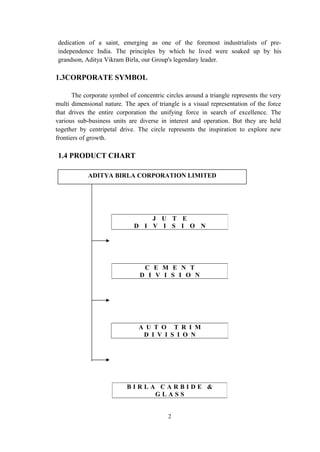
![Blasting: After drilling holes, this place is blasted by blasting materials inserted
inside the drilled part to break the huge rocks into pieces.
2.2 CRUSHER
These pieces of rocks are brought near to the crusher & are further processed.
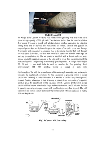
Fig2.2-Raw Material Processing
The crusher crushes these collected rocks into fine pieces of 50 mm size. It just breaks
down the huge rocks into compatible sizes with Impact /hammer mechanismsm
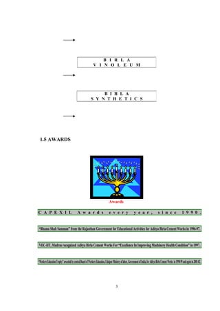
2.3 PRE-HOMOGENIZATION OF RAW MATERIAL:
In this process this crushed material l is arranged in the form of piles
with the help of stacker, to make it available for picking it up for further
processing.
Fig 2.3-Stacker
Here definite pile size is fixed. Laterite [Iron ore] is also mixed in this process. This
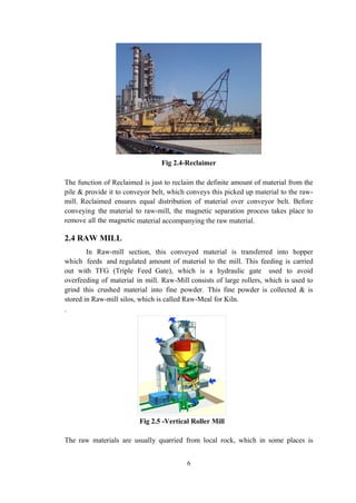
piled material is then reclaimed by the Reclaimed.
5](https://image.slidesharecdn.com/rep-151027034603-lva1-app6892/85/Aditya-birla-cement-training-report-5-320.jpg)

The document provides an overview of the Aditya Birla Group, a large Indian conglomerate. It discusses the company's origins in the 19th century with Seth Shiv Narayan Birla starting a cotton trading business. It expanded into various industries in the early 20th century under Ghanshyamdas Birla. The group now operates in over 40 countries with over 120,000 employees. The document also describes the cement production process used by the group's cement division, including mining of raw materials, crushing, blending, preheating and the rotary kiln production of clinker.


