The document provides a summary of the Razor E300 electric scooter design report. It includes:
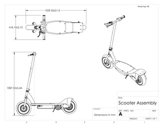
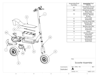
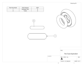
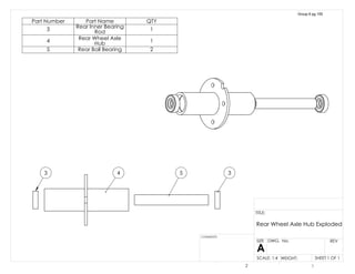
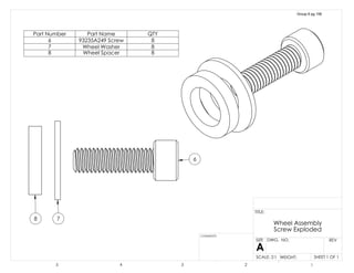
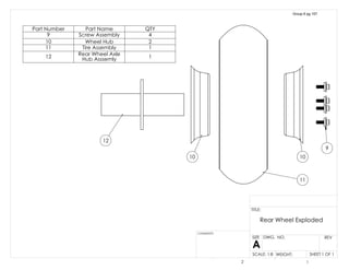
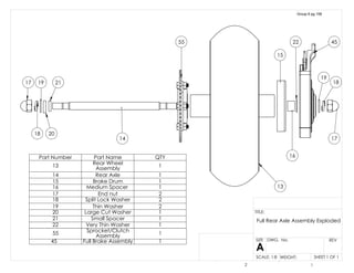
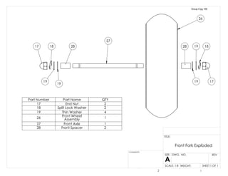
1) A parts list and description of the major components including the chain drive assembly, rear wheel assembly, front wheel assembly, and their subcomponents.
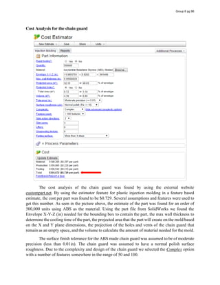
2) An introduction stating the report will analyze the design requirements, materials used, assembly process, cost analysis, and performance of the scooter's systems.
3) An overview of the report's contents including part descriptions, functional requirements, material analysis, assembly instructions, cost analysis, and performance evaluations.
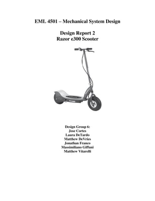
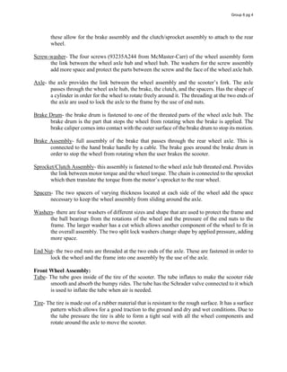

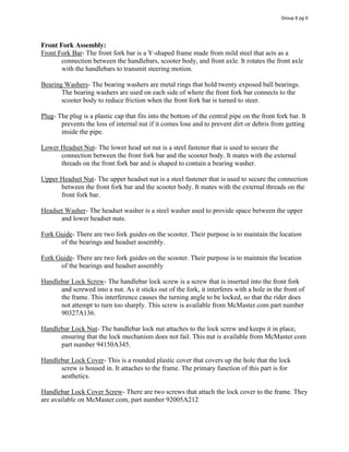
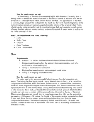
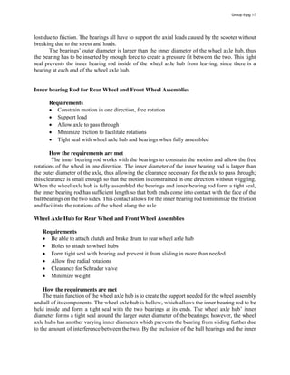
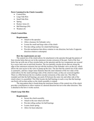
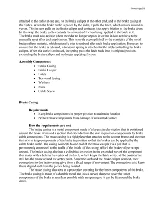
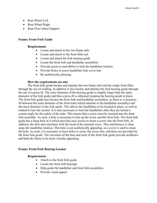

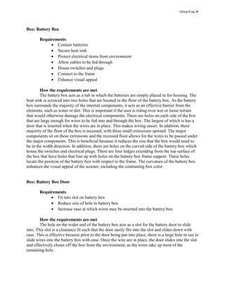
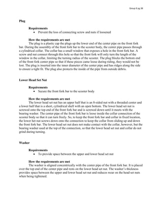
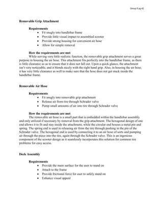

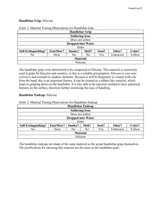
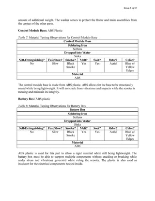
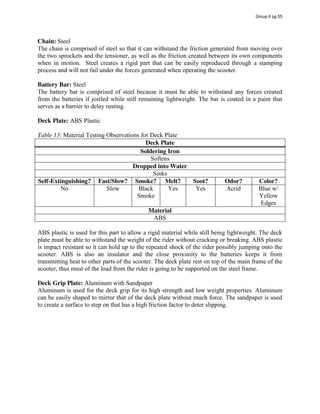

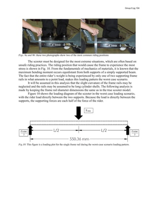
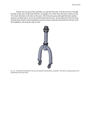
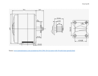
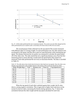
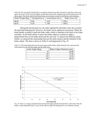
![Although that for a more in-depth analysis of heat transfer additional temperatures at
multiple locations would need to be taken, much can still be learned from the values calculated.
The simple addition of sixteen fins increased surface area by about 25% but nearly double the
amount of heat transfer compared with the sprocket side. This is attributed to the overall
effectiveness of the fins. It can also be seen from the table that the fins do not become very much
effective until the scooter has been running for quite some time and the temperature has been
raised notably.
The cast iron part of the motor takes up the majority of the surface area for the motor, but
can be seen to transfer heat significantly less per unit area. It can be hypothesized that this
happens due to the fact that the cast iron has lower thermal conductivity compared with the other
sides.
Along with the heat loss from natural convection that was calculated, some heat is
disbursed through radiation and also loss in the contact surface between the motor components.
The capabilities for finding these unknown heat losses require much more precise and elaborate
equipment that is beyond the scope of this course, but estimates can be made. If one looks and
takes into account that the motor runs at 250 W with an efficiency of about 78%, it can be seen
that heat loss accounts for about 55 W. The sum of all the convection heat losses calculated
reaches about 43.5 W. The additional 11.5 W can be attributed to certain surface areas not
included in the calculations, as well as some loss due to radiation. This is a reasonable
assumption that correlates well with all the data collected.
Group 6 pg 111
[1
]
[1] Source: www.motiondynamics.com.au/united-my1016-250w-24v-dc-motor-with-10-tooth-
chain-sprocket.html](https://image.slidesharecdn.com/167b763e-3c79-4fba-81a0-caa1a612387b-160126224906/85/Group-6-Design-Report-2-copy-112-320.jpg)
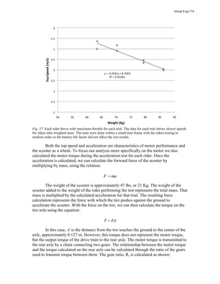
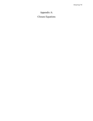
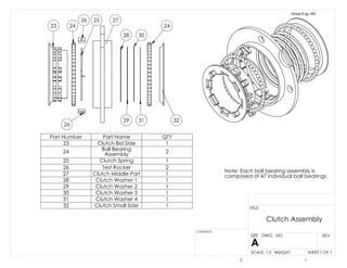
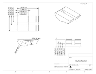
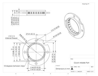
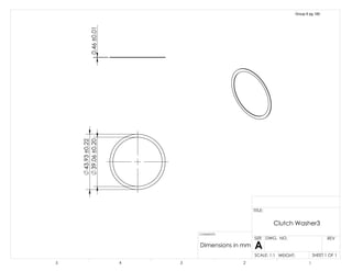
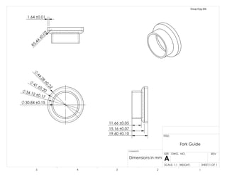
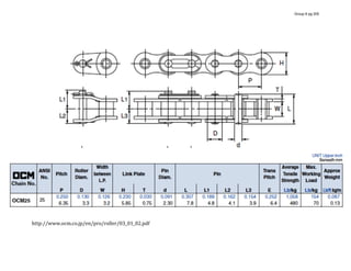
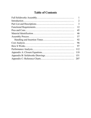
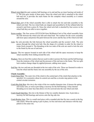
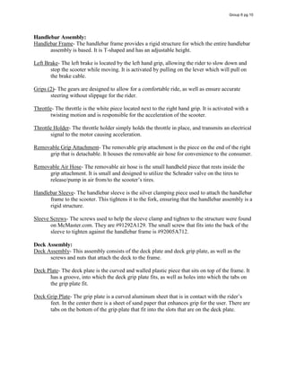
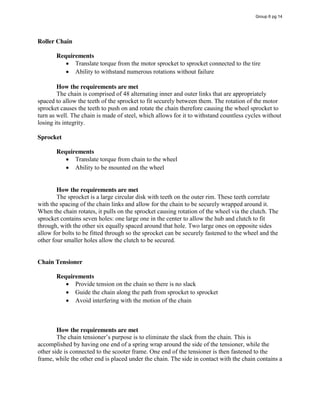
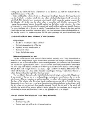
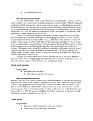
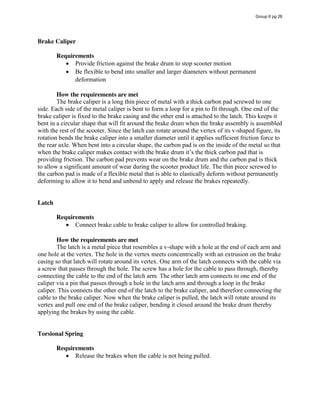
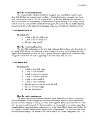
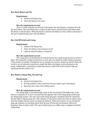
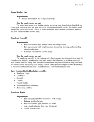
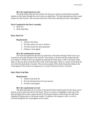
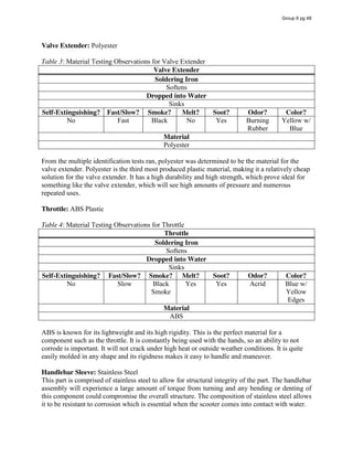
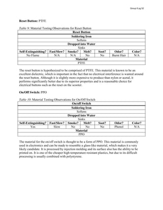
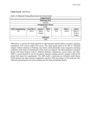
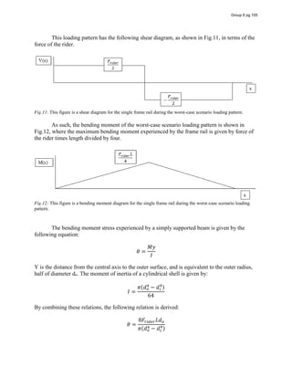
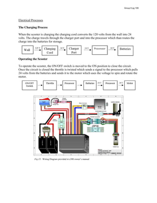
![Closure Equations
[1] Clutch Outer Rim OD and Sprocket ID (clearance)
Part Dimension Nominal
Dimension
Process
Tolerance
Actual Tolerance
Clutch Outer
Rim
Lc 26.94 mm 0.005 mm/mm 0.13 mm
Sprocket Ls 27.00 mm 0.005 mm/mm 0.14 mm
For a clearance fit, maximum material condition is of most concern.
𝐿 + ∆𝐿 + 𝐶 − (𝐿 − ∆𝐿 ) = 0
𝐶 = −0.2𝑚𝑚
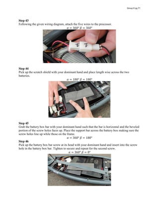
This means that clearance is not always guaranteed. As clearance is necessary for this feature for
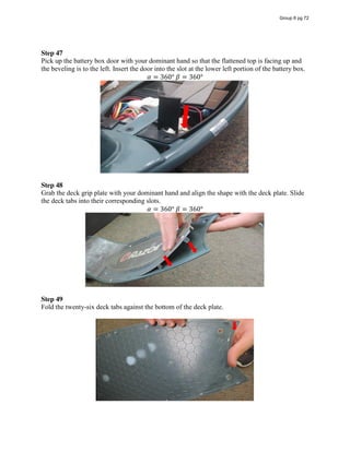
ease of assembly, it is necessary to change the process tolerance for both parts to 0.001 mm/mm.
This makes sense as both parts are of high importance and would likely need higher tolerance in
other dimensions. By changing the tolerance as previously mentioned, clearance is guaranteed
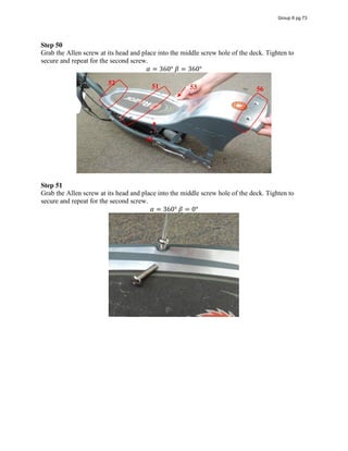
for all possible conditions. As the internal parts of the clutch are either obvious clearances
(spring and rocker, spring and central rim) or screwed together, they have not been considered.
As the two side rims screw into one another, they form their own space with respect to the ball
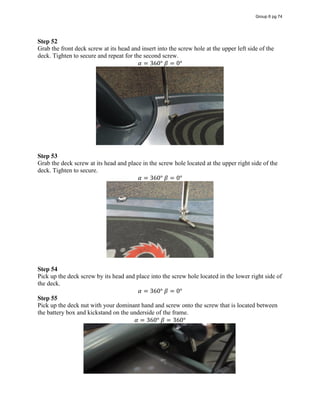
bearings and washers.
Group 6 pg 119](https://image.slidesharecdn.com/167b763e-3c79-4fba-81a0-caa1a612387b-160126224906/85/Group-6-Design-Report-2-copy-120-320.jpg)
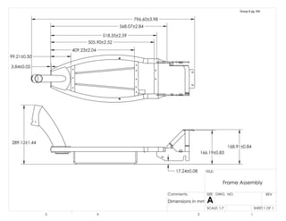
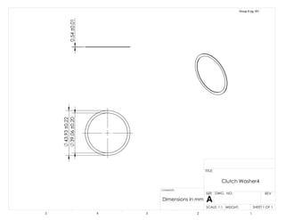
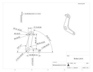
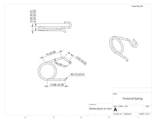
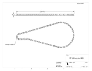
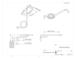
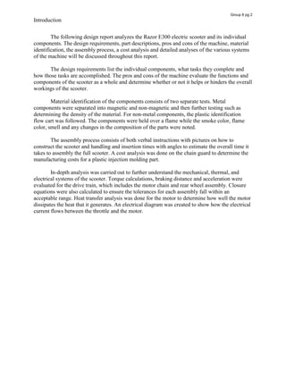
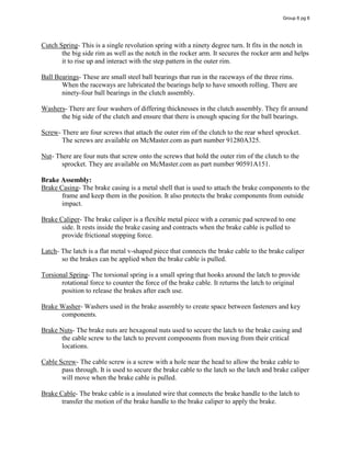
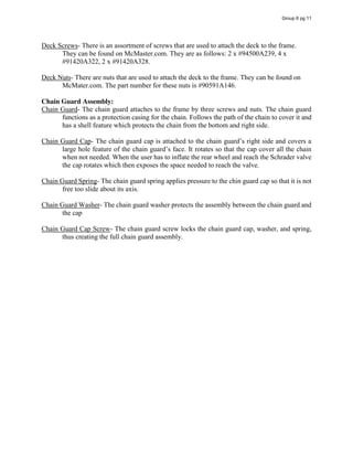
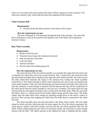
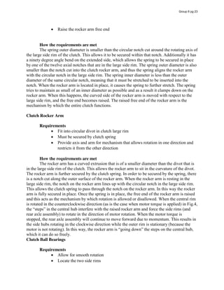
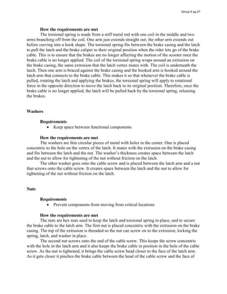
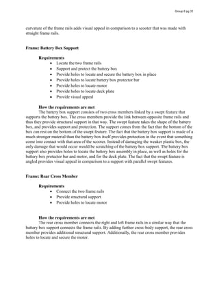
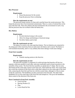
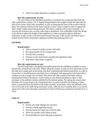
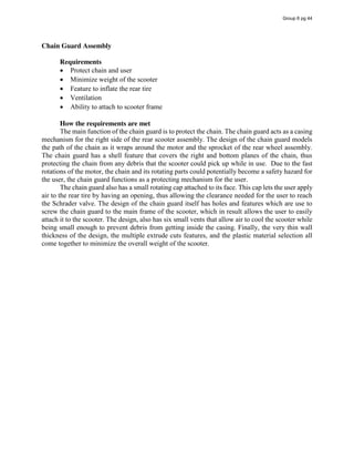
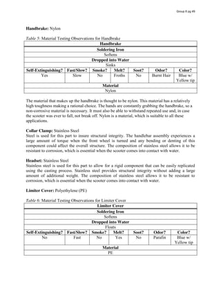
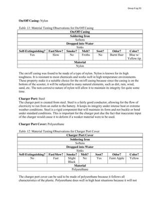
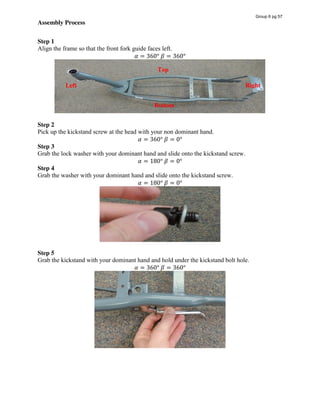
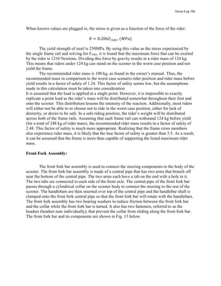
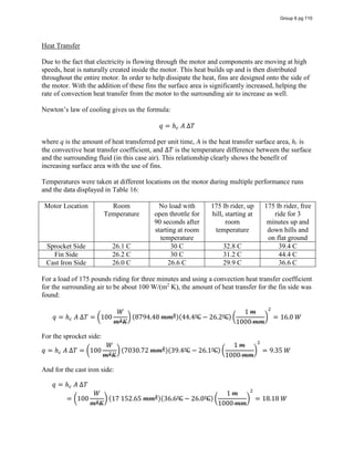
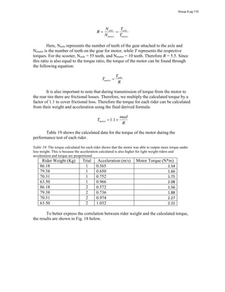
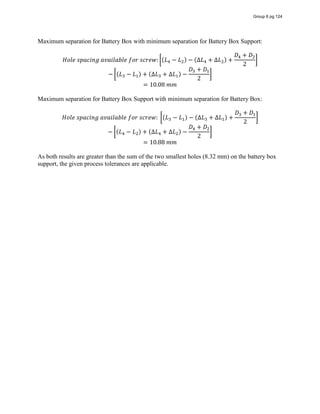
![[2] Tensioner Spring and Frame (clearance):
Part Dimension Nominal
Dimension
Process
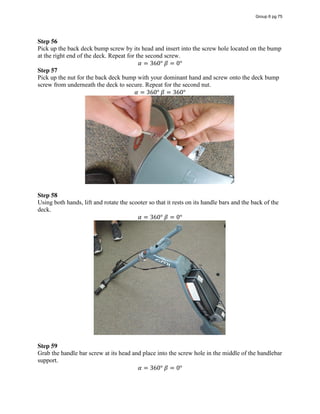
Tolerance
Actual Tolerance
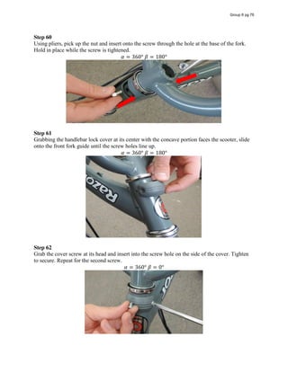
Tensioner Spring Ls 0.87 mm 0.008 mm/mm 0.01 mm
Rear Wheel
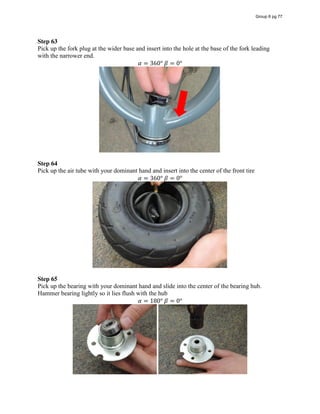
Right Frame
Lf 1.13 mm 0.005 mm/mm 0.01 mm
For clearance fit, maximum material condition is of most concern.
𝐿 + ∆𝐿 + 𝐶 − 𝐿 − ∆𝐿 = 0
𝐶 = 0.24𝑚𝑚
This means that a clearance is maintained for all possible material conditions.
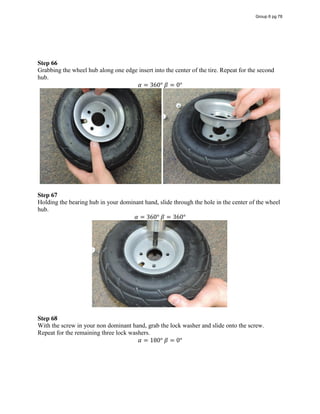
Group 6 pg 120](https://image.slidesharecdn.com/167b763e-3c79-4fba-81a0-caa1a612387b-160126224906/85/Group-6-Design-Report-2-copy-121-320.jpg)
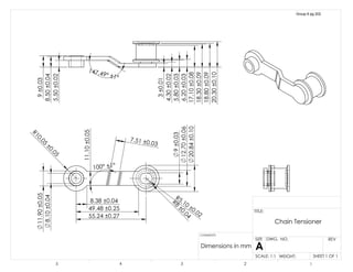
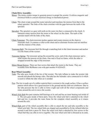
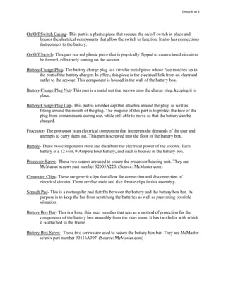
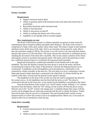
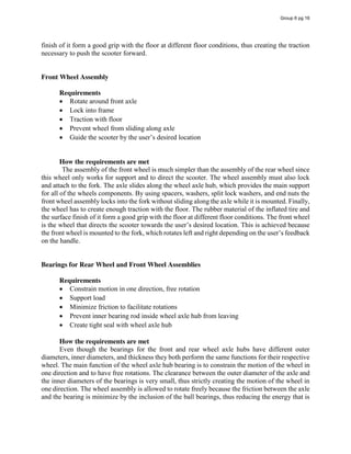
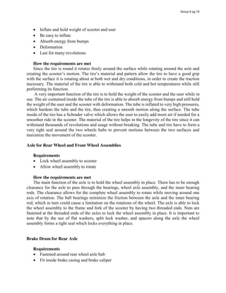
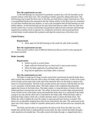
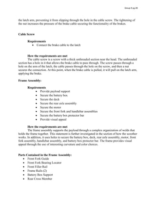
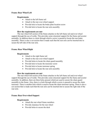
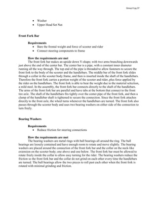
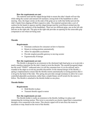
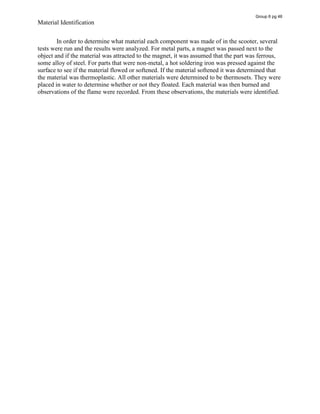
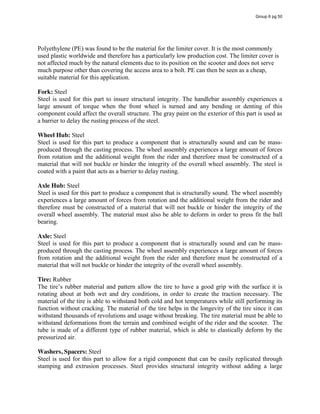
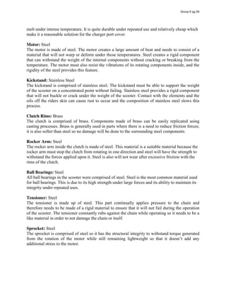
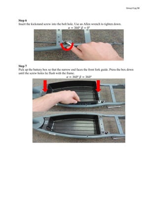
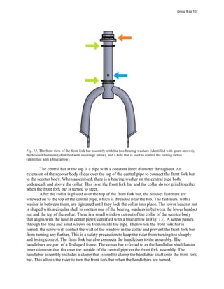
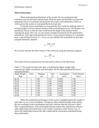
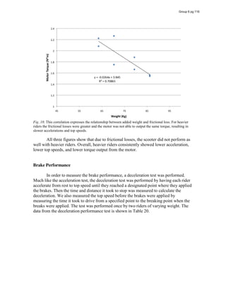
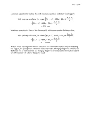
![[3] Chain and Tensioner (Clearance):
Part Dimension Nominal
Dimension
Process
Tolerance
Actual Tolerance
Chain Lc 3.38 mm 0.005 mm/mm 0.02 mm
Tensioner Lt 5.83 mm 0.005 mm/mm 0.03 mm
Note: The more chain-heavy side of the chain and tensioner interface is investigated in this
closure equation. There is more clearance to the other side of the tensioner, and hence the side
chosen corresponds with the worst case scenario.
For clearance fit, maximum material condition is of most concern.
𝐿 + ∆𝐿 + 𝐶 − (𝐿 − ∆𝐿 ) = 0
𝐶 = 2.4𝑚𝑚
This shows that there is a significantly large amount of clearance at all times for the chain and
tensioner when the chain is static or in a steady state. However this closure equation was
included to discuss the need for such a large clearance. As was discussed in the how it works
section, the unloaded motor rotates at 59.52 revolutions per second. This high rate of speed is
accompanied by a level of vibration. While these vibration calculations were not made, during
performance testing it was observed that the tensioner and chain interface move with respect to
each other as a result of this inherent vibration in the system. Vibration magnitudes were visually
observed to be larger during the transient state of the motor beginning to spin. What this closure
equation says is that on the more chain-heavy side of the chain and tensioner interface, there is
2.4 mm of clearance for these vibrations to occur. It is not known for sure exactly the magnitude
of the vibrations, however is can be assumed from the large clearance that the vibrations are not
enough to cause the chain to come into contact with the raised edge of the tensioner.
Group 6 pg 121](https://image.slidesharecdn.com/167b763e-3c79-4fba-81a0-caa1a612387b-160126224906/85/Group-6-Design-Report-2-copy-122-320.jpg)
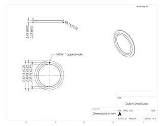
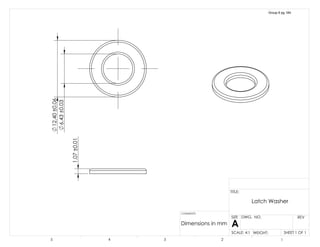
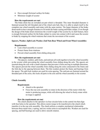
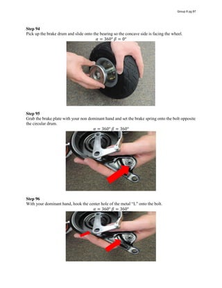
![[4] Chain and Sprocket (clearance):
Part Dimension Nominal
Dimension
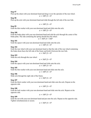
Process
Tolerance
Actual Tolerance
Chain Lc 1.60 mm 0.005 mm/mm 0.01 mm
Sprocket Ls 1.20 mm 0.005 mm/mm 0.01 mm
For clearance fit, maximum material condition is of most concern.
𝐿 + ∆𝐿 + 𝐶 − (𝐿 − ∆𝐿 ) = 0
𝐶 = 0.38𝑚𝑚
This means that for even the worst case maximum material condition, the required clearance is
attained.
Group 6 pg 122](https://image.slidesharecdn.com/167b763e-3c79-4fba-81a0-caa1a612387b-160126224906/85/Group-6-Design-Report-2-copy-123-320.jpg)
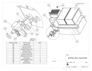
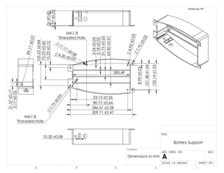
![[5] Battery Box and Frame Battery Box Support Holes Front Width (Line Up):
Part Dimension Nominal
Dimension
Process
Tolerance
Actual Tolerance
Battery Box L1 7.16 mm 0.008 mm/mm 0.05 mm
L3 97.15 mm 0.008 mm/mm 0.77 mm
D1 7.75 mm
D3 7.75 mm
Frame Battery
Support
L2 14.46 mm 0.005 mm/mm 0.07 mm
L4 104.05 mm 0.005 mm/mm 0.52 mm
D2 4.16 mm
D4 4.16 mm
For this application it is important that the holes line up for between components so that they can
be properly secured. In order to simplify calculations, it will be assumed that the error in hole
diameters is negligible in comparison to error in lengths. For this reason, all hole diameters will
be assumed to be constant as the diameters are much more accurate to machine than the hole
locations themselves. In the following calculations, the distance between the worst case hole
spacing will be investigated. The difference between the maximum material condition direction
and the minimum material condition must still result in a hole large enough to fit the required
screw through. In this case, if the total difference is not the sum of the diameters of the two
smaller holes, it is assumed that there is not enough clearance for the screw and the tolerances
will need to be changed.
Group 6 pg 123](https://image.slidesharecdn.com/167b763e-3c79-4fba-81a0-caa1a612387b-160126224906/85/Group-6-Design-Report-2-copy-124-320.jpg)
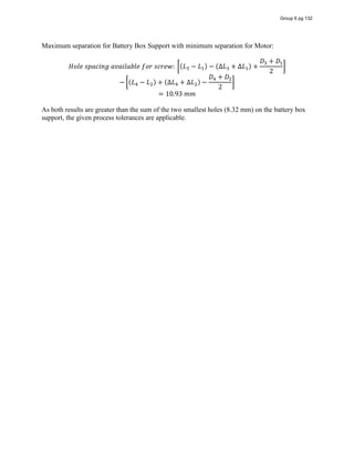
![[6] Battery Box and Frame Battery Box Support Holes Rear Width (Line Up):
Part Dimension Nominal
Dimension
Process
Tolerance
Actual Tolerance
Battery Box L1 11.86 mm 0.008 mm/mm 0.09 mm
L3 144.00 mm 0.008 mm/mm 1.15 mm
D1 7.75 mm
D3 7.75 mm
Frame Battery
Support
L2 19.56 mm 0.005 mm/mm 0.09 mm
L4 150.56 mm 0.005 mm/mm 0.75 mm
D2 4.95 mm
D4 4.58 mm
For this application it is important that the holes line up for between components so that they can
be properly secured. In order to simplify calculations, it will be assumed that the error in hole
diameters is negligible in comparison to error in lengths. For this reason, all hole diameters will
be assumed to be constant as the diameters are much more accurate to machine than the hole
locations themselves. In the following calculations, the distance between the worst case hole
spacing will be investigated. The difference between the maximum material condition direction
and the minimum material condition must still result in a hole large enough to fit the required
screw through. In this case, if the total difference is not the sum of the diameters of the two
smaller holes, it is assumed that there is not enough clearance for the screw and the tolerances
will need to be changed.
Group 6 pg 125](https://image.slidesharecdn.com/167b763e-3c79-4fba-81a0-caa1a612387b-160126224906/85/Group-6-Design-Report-2-copy-126-320.jpg)
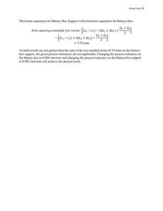
![[7] Battery Box and Frame Battery Box Support Holes Lengthwise (Line Up):
Part Dimension Nominal
Dimension
Process
Tolerance
Actual Tolerance
Battery Box L1 11.30 mm 0.008 mm/mm 0.09 mm
L3 321.01 mm 0.008 mm/mm 2.56 mm
D1 7.75 mm
D3 7.75 mm
Frame Battery
Support
L2 9.84 mm 0.005 mm/mm 0.05 mm
L4 319.62 mm 0.005 mm/mm 1.60 mm
D2 4.16 mm
D4 4.58 mm
For this application it is important that the holes line up for between components so that they can
be properly secured. In order to simplify calculations, it will be assumed that the error in hole
diameters is negligible in comparison to error in lengths. For this reason, all hole diameters will
be assumed to be constant as the diameters are much more accurate to machine than the hole
locations themselves. In the following calculations, the distance between the worst case hole
spacing will be investigated. The difference between the maximum material condition direction
and the minimum material condition must still result in a hole large enough to fit the required
screw through. In this case, if the total difference is not the sum of the diameters of the two
smaller holes, it is assumed that there is not enough clearance for the screw and the tolerances
will need to be changed.
Maximum separation for Battery Box with minimum separation for Battery Box Support:
𝐻𝑜𝑙𝑒 𝑠𝑝𝑎𝑐𝑖𝑛𝑔 𝑎𝑣𝑎𝑖𝑙𝑎𝑏𝑙𝑒 𝑓𝑜𝑟 𝑠𝑐𝑟𝑒𝑤: (𝐿 − 𝐿 ) − (∆𝐿 + ∆𝐿 ) +
𝐷 + 𝐷
2
− (𝐿 − 𝐿 ) + (∆𝐿 + ∆𝐿 ) −
𝐷 + 𝐷
2
= 7.89 𝑚𝑚
Group 6 pg 127](https://image.slidesharecdn.com/167b763e-3c79-4fba-81a0-caa1a612387b-160126224906/85/Group-6-Design-Report-2-copy-128-320.jpg)
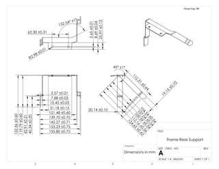
![[8] Motor Mount and Frame Holes Width (Line Up):
Part Dimension Nominal
Dimension
Process
Tolerance
Actual Tolerance
Motor L1 6.50 mm 0.005 mm/mm 0.03 mm
L3 48.50 mm 0.005 mm/mm 0.24 mm
D1 6.60 mm
D3 6.60 mm
Frame Battery
Support
L2 42.25 mm 0.005 mm/mm 0.21 mm
L4 84.79 mm 0.005 mm/mm 0.42 mm
D2 5.19 mm
D4 5.19 mm
For this application it is important that the holes line up for between components so that they can
be properly secured. In order to simplify calculations, it will be assumed that the error in hole
diameters is negligible in comparison to error in lengths. For this reason, all hole diameters will
be assumed to be constant as the diameters are much more accurate to machine than the hole
locations themselves. In the following calculations, the distance between the worst case hole
spacing will be investigated. The difference between the maximum material condition direction
and the minimum material condition must still result in a hole large enough to fit the required
screw through. In this case, if the total difference is not the sum of the diameters of the two
smaller holes, it is assumed that there is not enough clearance for the screw and the tolerances
will need to be changed.
Group 6 pg 129](https://image.slidesharecdn.com/167b763e-3c79-4fba-81a0-caa1a612387b-160126224906/85/Group-6-Design-Report-2-copy-130-320.jpg)
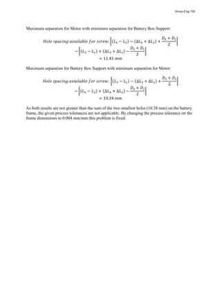
![[9] Motor Mount and Frame Holes Width (Line Up):
Part Dimension Nominal
Dimension
Process
Tolerance
Actual Tolerance
Motor L1 8.00 mm 0.008 mm/mm 0.04 mm
L3 102.77 mm 0.008 mm/mm 0.51 mm
D1 6.60 mm
D3 6.60 mm
Frame Battery
Support
L2 9.32 mm 0.005 mm/mm 0.05 mm
L4 103.83 mm 0.005 mm/mm 0.52 mm
D2 5.19 mm
D4 5.19 mm
For this application it is important that the holes line up for between components so that they can
be properly secured. In order to simplify calculations, it will be assumed that the error in hole
diameters is negligible in comparison to error in lengths. For this reason, all hole diameters will
be assumed to be constant as the diameters are much more accurate to machine than the hole
locations themselves. In the following calculations, the distance between the worst case hole
spacing will be investigated. The difference between the maximum material condition direction
and the minimum material condition must still result in a hole large enough to fit the required
screw through. In this case, if the total difference is not the sum of the diameters of the two
smaller holes, it is assumed that there is not enough clearance for the screw and the tolerances
will need to be changed.
Maximum separation for Motor with minimum separation for Battery Box Support:
𝐻𝑜𝑙𝑒 𝑠𝑝𝑎𝑐𝑖𝑛𝑔 𝑎𝑣𝑎𝑖𝑙𝑎𝑏𝑙𝑒 𝑓𝑜𝑟 𝑠𝑐𝑟𝑒𝑤: (𝐿 − 𝐿 ) − (∆𝐿 + ∆𝐿 ) +
𝐷 + 𝐷
2
− (𝐿 − 𝐿 ) + (∆𝐿 + ∆𝐿 ) −
𝐷 + 𝐷
2
= 10.41 𝑚𝑚
Group 6 pg 131](https://image.slidesharecdn.com/167b763e-3c79-4fba-81a0-caa1a612387b-160126224906/85/Group-6-Design-Report-2-copy-132-320.jpg)
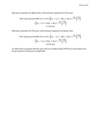
![[10] Battery Box and Processor Holes Width (Line Up):
Part Dimension Nominal
Dimension
Process
Tolerance
Actual Tolerance
Battery Box L1 15.08 mm 0.008 mm/mm 0.12 mm
L3 90.31 mm 0.008 mm/mm 0.72 mm
D1 4.20 mm
D3 4.20 mm
Processor L2 5.15 mm 0.005 mm/mm 0.03 mm
L4 80.15 mm 0.005 mm/mm 0.40 mm
D2 5.88 mm
D4 5.88 mm
For this application it is important that the holes line up for between components so that they can
be properly secured. In order to simplify calculations, it will be assumed that the error in hole
diameters is negligible in comparison to error in lengths. For this reason, all hole diameters will
be assumed to be constant as the diameters are much more accurate to machine than the hole
locations themselves. In the following calculations, the distance between the worst case hole
spacing will be investigated. The difference between the maximum material condition direction
and the minimum material condition must still result in a hole large enough to fit the required
screw through. In this case, if the total difference is not the sum of the diameters of the two
smaller holes, it is assumed that there is not enough clearance for the screw and the tolerances
will need to be changed.
Group 6 pg 133](https://image.slidesharecdn.com/167b763e-3c79-4fba-81a0-caa1a612387b-160126224906/85/Group-6-Design-Report-2-copy-134-320.jpg)

![[11] Battery Box and Processor Holes Length (Line Up):
Part Dimension Nominal
Dimension
Process
Tolerance
Actual Tolerance
Battery Box L1 20.64 mm 0.008 mm/mm 0.16 mm
L3 68.26 mm 0.008 mm/mm 0.54 mm
D1 4.20 mm
D3 4.20 mm
Processor L2 17.66 mm 0.005 mm/mm 0.08 mm
L4 65.48 mm 0.005 mm/mm 0.32 mm
D2 5.88 mm
D4 5.88 mm
For this application it is important that the holes line up for between components so that they can
be properly secured. In order to simplify calculations, it will be assumed that the error in hole
diameters is negligible in comparison to error in lengths. For this reason, all hole diameters will
be assumed to be constant as the diameters are much more accurate to machine than the hole
locations themselves. In the following calculations, the distance between the worst case hole
spacing will be investigated. The difference between the maximum material condition direction
and the minimum material condition must still result in a hole large enough to fit the required
screw through. In this case, if the total difference is not the sum of the diameters of the two
smaller holes, it is assumed that there is not enough clearance for the screw and the tolerances
will need to be changed.
Group 6 pg 135](https://image.slidesharecdn.com/167b763e-3c79-4fba-81a0-caa1a612387b-160126224906/85/Group-6-Design-Report-2-copy-136-320.jpg)
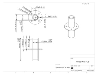
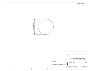
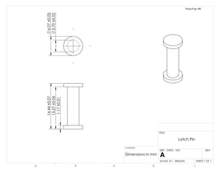
![[12] Wheel axle hub with inner rod and ball bearings
Part Dimension
Nominal
Dimension
Process
Tolerance
Actual
Tolerance
Rear Ball
Bearing
𝐿 , 7.97𝑚𝑚 0.005 𝑚𝑚 𝑚𝑚⁄ 0.040𝑚𝑚
Rear Wheel
Axle Hub
𝐿 , 132.60𝑚𝑚 0.005 𝑚𝑚 𝑚𝑚⁄ 0.663𝑚𝑚
Inner Bearing
Rod
𝐿 , 116.60𝑚𝑚 0.005 𝑚𝑚 𝑚𝑚⁄ 0.583𝑚𝑚
MMC L/LMC R
𝐿 , + ∆𝐿 , − 𝐿 , − ∆𝐿 , + 𝐿 , − ∆𝐿 , + 𝐿 , − ∆𝐿 , = 0
(132.60 + 0.663)𝑚𝑚 − (7.97 − 0.040) + (116.60 − 0.583) + (7.97 − 0.040) 𝑚𝑚 = 0
1.39𝑚𝑚 ≠ 0
LMC L/MMC R
𝐿 , − ∆𝐿 , − 𝐿 , + ∆𝐿 , + 𝐿 , + ∆𝐿 , + 𝐿 , + ∆𝐿 , = 0
(132.60 − 0.663)𝑚𝑚 − (7.97 + 0.040) + (116.60 + 0.583) + (7.97 + 0.040) 𝑚𝑚 = 0
−1.27𝑚𝑚 ≠ 0
𝐿 ,
𝐿 ,
𝐿 ,
𝐿 ,
Group 6 pg 137](https://image.slidesharecdn.com/167b763e-3c79-4fba-81a0-caa1a612387b-160126224906/85/Group-6-Design-Report-2-copy-138-320.jpg)
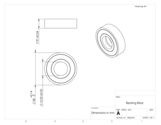
![[13] Axle: Interference fit wheel axle hub and ball bearing
Part Dimension
Nominal
Dimension
Process
Tolerance
Actual Tolerance
Rear Ball
Bearing
𝐷 , 28.00𝑚𝑚 0.005 𝑚𝑚 𝑚𝑚⁄ 0.14𝑚𝑚
Rear Wheel Axle
Hub
𝐷 , 27.92𝑚𝑚 0.005 𝑚𝑚 𝑚𝑚⁄ 0.14𝑚𝑚
Worst Case Scenario: MMC Inner wheel axle hub/LMC bearing outside diameter
𝐷 , + ∆𝐷 , + 𝐼 − 𝐷 , − ∆𝐷 , = 0
𝐼 = 𝐷 , − ∆𝐷 , − 𝐷 , − ∆𝐷 ,
𝐼 = (28.00 − 0.028 − 27.92 − 0.028)𝑚𝑚
𝐼 = −0.2𝑚 < 0, 𝑐ℎ𝑎𝑛𝑔𝑒 𝑡𝑜𝑙𝑒𝑟𝑎𝑛𝑐𝑒
Part Dimension
Nominal
Dimension
Process
Tolerance
Actual Tolerance
Rear Ball
Bearing
𝐷 , 28.00𝑚𝑚 0.000 𝑚𝑚 𝑚𝑚⁄ 0.0𝑚𝑚
Rear Wheel Axle
Hub
𝐷 , 27.92𝑚𝑚 0.005 𝑚𝑚 𝑚𝑚⁄ 0.07𝑚𝑚
𝐼 = (28.00 − 27.92 − 0.028)𝑚𝑚
𝐼 = −0.2𝑚 < 0, 𝑐ℎ𝑎𝑛𝑔𝑒 𝑡𝑜𝑙𝑒𝑟𝑎𝑛𝑐𝑒
𝐷 , = 28.00 ±
0.14
0.00
𝐷 , = 27.92 ±
0.07
0.14
𝐷 ,
𝐷 ,
Group 6 pg 138](https://image.slidesharecdn.com/167b763e-3c79-4fba-81a0-caa1a612387b-160126224906/85/Group-6-Design-Report-2-copy-139-320.jpg)
![[14] Rear Axle: Interference smallest wheel axle hub diameter/LMC Ball bearing outside
diameter
Part Dimension
Nominal
Dimension
Process
Tolerance
Actual
Tolerance
Rear Ball
Bearing
𝐷 , 28.00𝑚𝑚 0.005 𝑚𝑚 𝑚𝑚⁄ 0.140𝑚𝑚
Rear Wheel
Axle Hub
𝐷 , 26.88𝑚𝑚 0.005 𝑚𝑚 𝑚𝑚⁄ 0.135𝑚𝑚
Worst Case Scenario: MMC Smallest wheel axle hub diameter/LMC Bearing outside diameter
𝐷 , + ∆𝐷 , + 𝐼 − 𝐷 , − ∆𝐷 , = 0
𝐼 = 𝐷 , − ∆𝐷 , − 𝐷 , − ∆𝐷 ,
But we know from the previous closure equation for conditions to always work the tolerances
have to be:
𝐷 , = 28 ±
0.14
0.00
𝐷 , = 27.92 ±
0.07
0.14
𝐼 = (28.00 − 26.88 − 0.07)𝑚𝑚
𝐼 = 1.05𝑚𝑚 > 0, 𝑠𝑎𝑡𝑖𝑠𝑓𝑖𝑒𝑠 𝑐𝑜𝑛𝑑𝑖𝑡𝑖𝑜𝑛
𝐷 , = 26.88 ±
0.07
0.14
𝐷 ,
𝐷 ,
Group 6 pg 139](https://image.slidesharecdn.com/167b763e-3c79-4fba-81a0-caa1a612387b-160126224906/85/Group-6-Design-Report-2-copy-140-320.jpg)
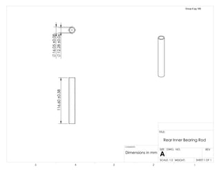
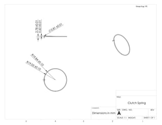
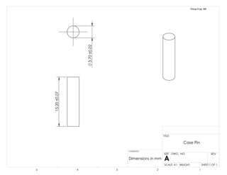
![[15] Rear Axle: Interference outer diameter of inside bearing rod with inner diameter of
ball bearing
Part Dimension
Nominal
Dimension
Process
Tolerance
Actual
Tolerance
Rear Ball
Bearing
𝐷 , 12.03𝑚𝑚 0.002 𝑚𝑚 𝑚𝑚⁄ 0.025𝑚𝑚
Inner Bearing
Rod
𝐷 , 16.05𝑚𝑚 0.005 𝑚𝑚 𝑚𝑚⁄ 0.081𝑚𝑚
Worst Case Scenario: MMC Bearing inner diameter/LMC Inner bearing rod outside diameter
𝐷 , + ∆𝐷 , + 𝐼 − 𝐷 , − ∆𝐷 , = 0
𝐼 = 𝐷 , − ∆𝐷 , − 𝐷 , − ∆𝐷 ,
𝐼 = (16.05 − 0.081 − 12.03 − 0.025)𝑚𝑚
𝐼 = 3.914𝑚𝑚 > 0, 𝑠𝑎𝑡𝑖𝑠𝑓𝑖𝑒𝑠 𝑐𝑜𝑛𝑑𝑖𝑡𝑖𝑜𝑛
𝐷 , = 12.03 ± 0.02
𝐷 , = 16.05 ± 0.08
𝐷 ,
𝐷 ,
Group 6 pg 140](https://image.slidesharecdn.com/167b763e-3c79-4fba-81a0-caa1a612387b-160126224906/85/Group-6-Design-Report-2-copy-141-320.jpg)
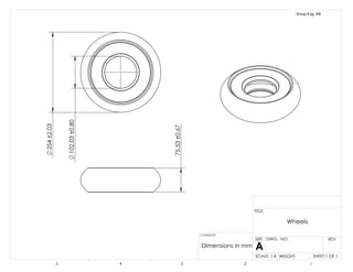
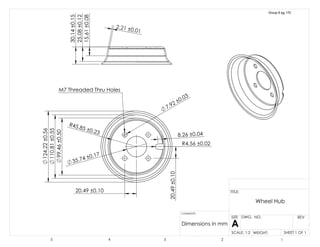
![[16] Rear Axle: Clearance wheel hub and wheel axle hub
Part Dimension
Nominal
Dimension
Process
Tolerance
Actual
Tolerance
Rear Wheel
Axle Hub
𝐷 , 35.24𝑚𝑚 0.005 𝑚𝑚 𝑚𝑚⁄ 0.177𝑚𝑚
Wheel Hub 𝐷 , 35.73𝑚𝑚 0.005 𝑚𝑚 𝑚𝑚⁄ 0.179𝑚𝑚
Worst Case Scenario: MMC Outer Diameter of wheel axle hub/LMC wheel hub Inside Diameter
𝐷 , + ∆𝐷 , + 𝐶 − 𝐷 , − ∆𝐷 , = 0
𝐶 = 𝐷 , − ∆𝐷 , − 𝐷 , − ∆𝐷 ,
𝐶 = (35.73 − 0.179 − 35.24 − 0.177)𝑚𝑚
𝐶 = 0.14𝑚𝑚 > 0, 𝑠𝑎𝑡𝑖𝑠𝑓𝑖𝑒𝑠 𝑐𝑜𝑛𝑑𝑖𝑡𝑖𝑜𝑛
𝐷 , = 35.24 ± 0.17
𝐷 , = 35.73 ± 0.17
𝐷 ,
𝐷 ,
Group 6 pg 141](https://image.slidesharecdn.com/167b763e-3c79-4fba-81a0-caa1a612387b-160126224906/85/Group-6-Design-Report-2-copy-142-320.jpg)
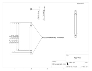
![[17] Rear Axle: Clearance between inner diameter of rod and axle outer diameter
Part Dimension Nominal
Dimension
Process
Tolerance
Actual
Tolerance
Rear Inner
Bearing Rod
𝐷 , 12.28𝑚𝑚 0.005 𝑚𝑚 𝑚𝑚⁄ 0.062𝑚𝑚
Rear Axle 𝐷 , 11.93𝑚𝑚 0.005 𝑚𝑚 𝑚𝑚⁄ 0.060𝑚𝑚
Worst Case Scenario: MMC axle outer diamter/LMC inner diameter of inner bearing rod
𝐷 , + ∆𝐷 , + 𝐶 − 𝐷 , − ∆𝐷 , = 0
𝐶 = 𝐷 , − ∆𝐷 , − 𝐷 , − ∆𝐷 ,
𝐶 = (12.28 − 0.062 − 11.93 − 0.060)𝑚𝑚
𝐶 = 0.228𝑚𝑚 > 0, 𝑠𝑎𝑡𝑖𝑠𝑓𝑖𝑒𝑠 𝑐𝑜𝑛𝑑𝑖𝑡𝑖𝑜𝑛
𝐷 , = 12.28 ± 0.06
𝐷 , = 11.93 ± 0.06
𝐷 ,
𝐷 ,
Group 6 pg 142](https://image.slidesharecdn.com/167b763e-3c79-4fba-81a0-caa1a612387b-160126224906/85/Group-6-Design-Report-2-copy-143-320.jpg)
![[18] Rear Axle: Clearance between inner diameter of bearing and axle outer diameter
Part Dimension Nominal
Dimension
Process
Tolerance
Actual
Tolerance
Rear Ball
Bearing
𝐷 , 12.03𝑚𝑚 0.002 𝑚𝑚 𝑚𝑚⁄ 0.025𝑚𝑚
Rear Axle 𝐷 , 11.93𝑚𝑚 0.005 𝑚𝑚 𝑚𝑚⁄ 0.060𝑚𝑚
Worst Case Scenario: MMC axle outer diameter/LMC bearing inner diameter
𝐷 , + ∆𝐷 , + 𝐶 − 𝐷 , − ∆𝐷 , = 0
𝐶 = 𝐷 , − ∆𝐷 , − 𝐷 , − ∆𝐷 ,
𝐶 = (12.03 − 0.025 − 11.93 − 0.060)𝑚𝑚
𝐶 = 0.015𝑚𝑚 > 0, 𝑠𝑎𝑡𝑖𝑠𝑓𝑖𝑒𝑠 𝑐𝑜𝑛𝑑𝑖𝑡𝑖𝑜𝑛
𝐷 , = 12.03 ± 0.02
𝐷 , = 11.93 ± 0.06
𝐷 , 𝐷 ,
Group 6 pg 143](https://image.slidesharecdn.com/167b763e-3c79-4fba-81a0-caa1a612387b-160126224906/85/Group-6-Design-Report-2-copy-144-320.jpg)
![[19] Spacing: Clearance Wheel hub and Wheel Axle holes
Part Dimension Nominal
Dimension
Process
Tolerance
Actual
Tolerance
Wheel Hub Screw Hole 𝐷 7.92𝑚𝑚 0.005 𝑚𝑚 𝑚𝑚⁄ 0.040𝑚𝑚
Wheel Axle Hub Screw
Hole
𝐷 6.80𝑚𝑚 0.005 𝑚𝑚 𝑚𝑚⁄ 0.034𝑚𝑚
Length Wheel Hub 𝐿 20.49𝑚𝑚 0.005 𝑚𝑚 𝑚𝑚⁄ 0.103𝑚𝑚
Length Wheel Axle
Hub
𝐿 20.49𝑚𝑚 0.005 𝑚𝑚 𝑚𝑚⁄ 0.103𝑚𝑚
MMC of the Wheel Axle Hub/LMC Wheel Hub
𝐿 − ∆𝐿 +
1
2
(𝐷 − ∆𝐷 ) − 𝐿 + ∆𝐿 +
1
2
(𝐷 + ∆𝐷 ) + 𝐶 = 0
𝐶 = 𝐿 − ∆𝐿 +
1
2
𝐷 −
1
2
∆𝐷 − 𝐿 − ∆𝐿 −
1
2
𝐷 −
1
2
∆𝐷
𝐶 = 20.49 − 0.103 +
1
2
(7.92) −
1
2
(0.040) − 20.49 − 0.103 −
1
2
(6.80) −
1
2
(0.034) 𝑚𝑚
𝐶 = .801𝑚𝑚 > 0, ℎ𝑜𝑙𝑒𝑠 𝑤𝑖𝑙𝑙 𝑎𝑙𝑤𝑎𝑦𝑠 𝑎𝑙𝑖𝑔𝑛
LMC of the Wheel Axle Hub/MMC Wheel Hub
𝐿 + ∆𝐿 +
1
2
(𝐷 + ∆𝐷 ) − 𝐿 − ∆𝐿 +
1
2
(𝐷 − ∆𝐷 ) + 𝐶 = 0
𝐶 = 𝐿 + ∆𝐿 +
1
2
𝐷 +
1
2
∆𝐷 − 𝐿 + ∆𝐿 −
1
2
𝐷 +
1
2
∆𝐷
𝐶 = 20.49 + 0.103 +
1
2
(7.92) +
1
2
(0.040) − 20.49 + 0.103 −
1
2
(6.80) +
1
2
(0.034) 𝑚𝑚
𝐷
𝐷
𝐿
𝐿
Group 6 pg 144](https://image.slidesharecdn.com/167b763e-3c79-4fba-81a0-caa1a612387b-160126224906/85/Group-6-Design-Report-2-copy-145-320.jpg)
![[20] Rear Axle: Clearance between frame and all axle components
𝐿
𝐿
𝐿
𝐿
𝐿
𝐿
𝐿
TOP
BOTTOM
Group 6 pg 146](https://image.slidesharecdn.com/167b763e-3c79-4fba-81a0-caa1a612387b-160126224906/85/Group-6-Design-Report-2-copy-147-320.jpg)
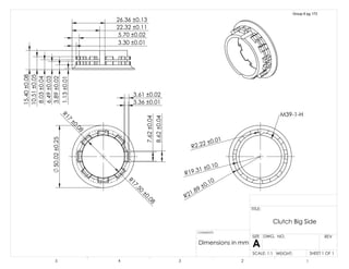
![[21] Rear Axle: Clearance between Sprocket and Clutch
Part Dimension Nominal
Dimension
Process
Tolerance
Actual
Tolerance
Sprocket 𝐷 , 54.00𝑚𝑚 0.002 𝑚𝑚 𝑚𝑚⁄ 0.108𝑚𝑚
Clutch 𝐷 , 53.88𝑚𝑚 0.002 𝑚𝑚 𝑚𝑚⁄ 0.108𝑚𝑚
Worst Case Scenario: MMC Clutch/LMC Sprocket
𝐷 , + ∆𝐷 , + 𝐶 − 𝐷 , − ∆𝐷 , = 0
𝐶 = 𝐷 , − ∆𝐷 , − 𝐷 , − ∆𝐷 ,
𝐶 = (54.00 − 0.108 − 53.88 − 0.108)𝑚𝑚
𝐶 = −0.096𝑚𝑚 < 0, 𝑐ℎ𝑎𝑛𝑔𝑒 𝑡𝑜𝑙𝑒𝑟𝑎𝑛𝑐𝑒 𝑜𝑓 𝑐𝑙𝑢𝑡𝑐ℎ
𝐷 , = 54.00 ± 0.10
𝐿 = 53.88 ±
0.00
0.10
𝐷 ,
𝐷 ,
Group 6 pg 148](https://image.slidesharecdn.com/167b763e-3c79-4fba-81a0-caa1a612387b-160126224906/85/Group-6-Design-Report-2-copy-149-320.jpg)
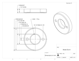
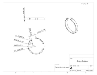
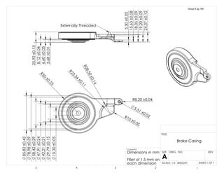
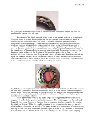
![[22] Rear Axle: Clearance between casing caliprer and brake drum
Part Dimension Nominal
Dimension
Process
Tolerance
Actual
Tolerance
Brake Drum 𝐷 , 80.34𝑚𝑚 0.005 𝑚𝑚 𝑚𝑚⁄ 0.402𝑚𝑚
Brake Caliper 𝐷 , 82.63𝑚𝑚 0.005 𝑚𝑚 𝑚𝑚⁄ 0.412𝑚𝑚
Worst Case Scenario: MMC Brake Drum outer diamter/LMC Brake Caliper inner diameter
𝐷 , + ∆𝐷 , + 𝐶 − 𝐷 , − ∆𝐷 , = 0
𝐶 = 𝐷 , − ∆𝐷 , − 𝐷 , − ∆𝐷 ,
𝐶 = (82.63 − 0.412 − 80.34 − 0.402)𝑚𝑚
𝐶 = 1.48𝑚𝑚 > 0, 𝑠𝑎𝑡𝑖𝑠𝑓𝑖𝑒𝑠 𝑐𝑜𝑛𝑑𝑖𝑡𝑖𝑜𝑛
𝐷 , = 80.34 ± 0.40
𝐷 , = 82.63 ± 0.41
𝐷 ,
𝐷 ,
Group 6 pg 149](https://image.slidesharecdn.com/167b763e-3c79-4fba-81a0-caa1a612387b-160126224906/85/Group-6-Design-Report-2-copy-150-320.jpg)
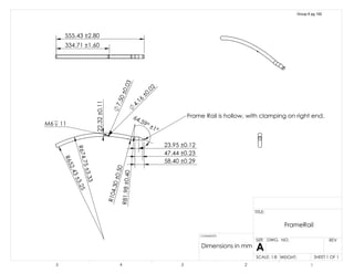
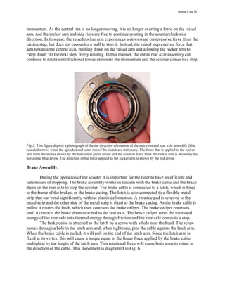
![[23] Rear Axle: Clearance between rear axle and frame
Part Dimension Nominal
Dimension
Process
Tolerance
Actual
Tolerance
Frame Space 𝐷 10.34𝑚𝑚 0.005 𝑚𝑚 𝑚𝑚⁄ 0.052𝑚𝑚
Rear Axle 𝐷 , 9.81𝑚𝑚 0.005 𝑚𝑚 𝑚𝑚⁄ 0.050𝑚𝑚
Worst Case Scenario: MMC Rear Axle outer diamter/LMC Frame Spacing
𝐷 , + ∆𝐷 , + 𝐶 − 𝐷 − ∆𝐷 = 0
𝐶 = 𝐷 − ∆𝐷 − 𝐷 , − ∆𝐷 ,
𝐶 = (10.34 − 0.052 − 9.81 − 0.050)𝑚𝑚
𝐶 = 0.43𝑚𝑚 > 0, 𝑠𝑎𝑡𝑖𝑠𝑓𝑖𝑒𝑠 𝑐𝑜𝑛𝑑𝑖𝑡𝑖𝑜𝑛
𝐷 = 10.34 ± 0.05
𝐷 , = 9.81 ± 0.05
𝐷
𝐷 ,
Group 6 pg 150](https://image.slidesharecdn.com/167b763e-3c79-4fba-81a0-caa1a612387b-160126224906/85/Group-6-Design-Report-2-copy-151-320.jpg)