Design of Fuzzy Logic Controller for Speed Regulation of BLDC motor using MATLAB

Brushless DC (BLDC) motors drives are one of the electrical drives that are rapidly gaining popularity, due to their high efficiency, good dynamic response and low maintenance. The design and development of a BLDC motor drive for commercial applications is presented. The aim of paper is to design a simulation model of inverter fed PMBLDC motor with Fuzzy logic controller. Fuzzy logic controller is developed using fuzzy logic tool box which is available in Matlab. FIS editor used to create .FIS file which contains the Fuzzy Logic Membership function and Rule base. And membership functions of desired output. After creating .FIS file it is implemented in the Matlab Simulink. And the BLDC motor is run satisfactorily using the Fuzzy logic controller.

Recommended
Recommended
More Related Content
What's hot
What's hot (19)
Viewers also liked
Viewers also liked (19)
Similar to Design of Fuzzy Logic Controller for Speed Regulation of BLDC motor using MATLAB
Similar to Design of Fuzzy Logic Controller for Speed Regulation of BLDC motor using MATLAB (20)
More from ijsrd.com
More from ijsrd.com (20)
Recently uploaded
Recently uploaded (20)
Design of Fuzzy Logic Controller for Speed Regulation of BLDC motor using MATLAB
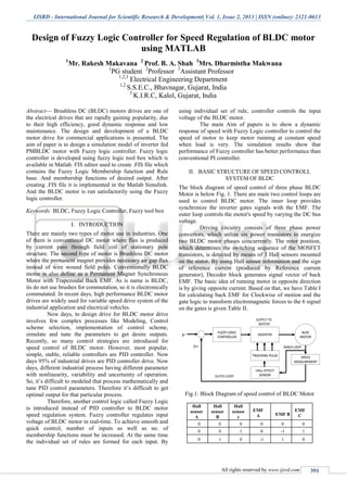
- 1. IJSRD - International Journal for Scientific Research & Development| Vol. 1, Issue 2, 2013 | ISSN (online): 2321-0613 All rights reserved by www.ijsrd.com 391 Design of Fuzzy Logic Controller for Speed Regulation of BLDC motor using MATLAB 1 Mr. Rakesh Makavana 2 Prof. B. A. Shah 3 Mrs. Dharmistha Makwana 1 PG student 2 Professor 3 Assistant Professor 1,2,3 Electrical Engineering Department 1,2 S.S.E.C., Bhavnagar, Gujarat, India 3 K.I.R.C, Kalol, Gujarat, India Abstract— Brushless DC (BLDC) motors drives are one of the electrical drives that are rapidly gaining popularity, due to their high efficiency, good dynamic response and low maintenance. The design and development of a BLDC motor drive for commercial applications is presented. The aim of paper is to design a simulation model of inverter fed PMBLDC motor with Fuzzy logic controller. Fuzzy logic controller is developed using fuzzy logic tool box which is available in Matlab. FIS editor used to create .FIS file which contains the Fuzzy Logic Membership function and Rule base. And membership functions of desired output. After creating .FIS file it is implemented in the Matlab Simulink. And the BLDC motor is run satisfactorily using the Fuzzy logic controller. Keywords: BLDC, Fuzzy Logic Controller, Fuzzy tool box I. INTRODUCTION There are mainly two types of motor use in industries. One of them is conventional DC motor where flux is produced by current pass through field coil of stationary pole structure. The second type of motor is Brushless DC motor where the permanent magnet provides necessary air gap flux instead of wire wound field poles. Conventionally BLDC motor is also define as a Permanent Magnet Synchronous Motor with Trapezoidal Back EMF. As is name is BLDC, its do not use brushes for commutation, so it is electronically commutated. In recent days, high performance BLDC motor drives are widely used for variable speed drive system of the industrial application and electrical vehicles. Now days, to design drive for BLDC motor drive involves few complex processes like Modeling, Control scheme selection, implementation of control scheme, simulate and tune the parameters to get desire outputs. Recently, so many control strategies are introduced for speed control of BLDC motor. However, most popular, simple, stable, reliable controllers are PID controller. Now days 95% of industrial drives are PID controller drive. Now days, different industrial process having different parameter with nonlinearity, variability and uncertainty of operation. So, it’s difficult to modeled that process mathematically and tune PID control parameters. Therefore it’s difficult to get optimal output for that particular process. Therefore, another control logic called Fuzzy Logic is introduced instead of PID controller to BLDC motor speed regulation system. Fuzzy controller regulates input voltage of BLDC motor in real-time. To achieve smooth and quick control, number of inputs as well as no. of membership functions must be increased. At the same time the individual set of rules are formed for each input. By using individual set of rule, controller controls the input voltage of the BLDC motor. The main Aim of papers is to show a dynamic response of speed with Fuzzy Logic controller to control the speed of motor to keep motor running at constant speed when load is very. The simulation results show that performance of Fuzzy controller has better performance than conventional PI controller. II. BASIC STRUCTURE OF SPEED CONTROLL SYSTEM OF BLDC The block diagram of speed control of three phase BLDC Motor is below Fig. 1. There are main two control loops are used to control BLDC motor. The inner loop provides synchronize the inverter gates signals with the EMF. The outer loop controls the motor's speed by varying the DC bus voltage. Driving circuitry consists of three phase power convertors, which utilize six power transistors to energize two BLDC motor phases concurrently. The rotor position, which determines the switching sequence of the MOSFET transistors, is detected by means of 3 Hall sensors mounted on the stator. By using Hall sensor information and the sign of reference current (produced by Reference current generator), Decoder block generates signal vector of back EMF. The basic idea of running motor in opposite direction is by giving opposite current. Based on that, we have Table I for calculating back EMF for Clockwise of motion and the gate logic to transform electromagnetic forces to the 6 signal on the gates is given Table II. INVERTER HALL EFFECT SENSOR FUZZY LOGIC CONTROLLER BLDC MOTOR SUPPLY TO MOTOR TRIGERING PULSE SPEED MEASUREMENT µr µm OUTER LOOP INNER LOOP Fig.1: Block Diagram of speed control of BLDC Motor Hall sensor A Hall sensor B Hall sensor c EMF A EMF B EMF C 0 0 0 0 0 0 0 0 1 0 -1 1 0 1 0 -1 1 0
- 2. Design of Fuzzy Logic Controller for Speed Regulation of BLDC motor using MATLAB (IJSRD/Vol. 1/Issue 2/2013/0081) All rights reserved by www.ijsrd.com 392 0 1 1 -1 0 1 1 0 0 1 0 -1 1 0 1 1 -1 0 1 1 0 0 1 -1 1 1 1 0 0 0 Table. 1: Clockwise Rotation EMF A EMF B EMF C Q1 Q2 Q3 Q4 Q5 Q6 0 0 0 0 0 0 0 0 0 0 -1 1 0 0 0 1 1 0 -1 1 0 0 1 1 0 0 0 -1 0 1 0 1 0 0 1 0 1 0 -1 1 0 0 0 0 1 1 -1 0 1 0 0 1 0 0 0 1 -1 0 0 1 0 0 1 0 0 0 0 0 0 0 0 0 Table. 2: Gate Logic III. DESIGN OF FUZZY LOGIC CONTROLLER FOR BLDC Fuzzy logic’s linguistic terms are most often expressed in the form of logical implications, such as If-Then rules. These rules define a range of values known as fuzzy membership functions. Fuzzy membership functions may be in the form of triangle, a trapezoid; a bell .In figure 2 fuzzy controller calculates an "error" value as the difference between reference speed and actual speed. Fig.2: Membership functions of fuzzy controller Seven membership function has used, functions defined as: Negative Big (NB), Negative Medium (NM), Negative Small (NS), Zero (Z), Positive Small (PS), Positive Medium (PM), and Positive Big (PB) given 49 rules in Table III. The min-max compositional rule of inference and the center-of-gravity method have been used in defuzzifier process. If input 1 is NB and input 2 is NB Then u is PB, If e1 is NB and e2 is NM Then u is PB, If e1 is NB and e2 is NS Then u is PM, If e1 is NB and e2 is Z Then u is PM, ………………………………………… And go on for all inputs. Input 1: Input 2 : Derivative of Error Error NB NM NS Z PS PM PB NB PB PB PM PM PS PS Z NM PB PM PM PS PS Z NS NS PM PM PS PS Z NS NS Z PM PS PS Z NS NS NM PS PS PS Z NS NS NM NM PM PS Z NS NS NM NM NB PB Z NS NS NM NM NB NB Table. 3: Fuzzy Rule Table MATLAB/Fuzzy Logic Toolbox is used to simulate FLC which can be integrated into simulations with Simulink. The FLC designed through the FIS editor is transferred to Matlab-Workspace by the command “Export to file”. Then, we have FIS file which is used in Simulink block name Fuzzy Logic Controller. We have to specify the file name in that block and put file into same path of model file. Fig.6.10 Shows the Matlab model of Implementing Fuzzy logic Controller for BLDC motor. Fig.3: FIS Editor for Creating FIS file Fig.4: Membership Function Plot for Input-1
- 3. Design of Fuzzy Logic Controller for Speed Regulation of BLDC motor using MATLAB (IJSRD/Vol. 1/Issue 2/2013/0081) All rights reserved by www.ijsrd.com 393 Fig.5: Membership Function Plot for Input-2 Fig.6: Membership Function Plot for Output In FIS editor, after defining all input and Output. We have to specify the rule base for that. In our case we have 49 rules to define. After that we export .fis file. Fig. shows result for input1 & input2 are zero. And same time calculated output if 488. Fig.7: Rule base view of all 49 rules. IV. SIMULATION The computer simulation runs such that the speed of the BLDC motor remains at 3000 rpm (reference speed) in the steady state, with load of 3 N.m. This constraint is provided by means of the fuzzy logic controller. Error is calculated by subtracting the reference speed and the speed at the moment. Taking the difference between the present error and the error of the previous sampling period, change of error is calculated. According to the error and the change of error, fuzzy logic controller calculates voltage change that should be applied to the BLDC motor. Fig.8: Matlab simulation model for BLDC with Fuzzy Controller Simulation Results
- 4. Design of Fuzzy Logic Controller for Speed Regulation of BLDC motor using MATLAB (IJSRD/Vol. 1/Issue 2/2013/0081) All rights reserved by www.ijsrd.com 394 V. CONCLUSION A fuzzy logic controller (FLC) has been employed for the speed control of PMBLDC. The simulation model which is implemented in MATLAB/Simulink environment allows that many dynamic characteristics such as phase currents, voltages, rotor speed, and mechanical torque can be effectively considered. Furthermore, the control algorithms, FLC and PI have been compared by using the developed model. It is seen that the desired real speed and torque values could be reached in a short time by FLC controller. Fuzzy logic speed controller improved the performance of PMBLDC Drive. REFERENCES [1] “Modeling and simulation of three level inverter FED PMBLDC drive using AI technique”, Narmadha T.V, vol.2, NO.1, 2010, PP.69-82. [2] “Efficient Modeling for a Brushless DC Motor Drive’’, P C K Luk' , C K Lee IEEE conference on industrial electronics (IECON), 1994. [3] “fuzzy logic in control systems: fuzzy logic control part 1 & part 2”, C.C.Lee,IEEE Trans. Syst., man,cybren,vol.20,no.2,pp.404-435, mar./apr.1990 [4] “Design of a Hybrid Fuzzy Logic Proportional Plus Conventional Integral-Derivative Controller” Wei Li, IEEE TRANSACTIONS ON FUZZY SYSTEMS, VOL. 6, NO. 4, NOVEMBER 1998 449-463
- 5. Design of Fuzzy Logic Controller for Speed Regulation of BLDC motor using MATLAB (IJSRD/Vol. 1/Issue 2/2013/0081) All rights reserved by www.ijsrd.com 395 [5] “Fuzzy Logic Based Position-Sensor less Speed Control of Multi Level Inverter Fed PMBLDC Drive”, Narmadha T.V, Thyagarajan T. JOURNAL OF ADVANCES IN INFORMATION TECHNOLOGY, VOL. 1, NO. 1, FEBRUARY 2010 52-58 [6] “Review of Multilevel Voltage Source Inverter Topologies And Control Schemes”, Ilhami Colak , Ersan Kabalci , Ramazan Bayindir [7] “Realization of Fuzzy Logic Controlled BLDC motor drive using Matlab/Simulink” Mehmet Çunkaş and Omer Aydoğdu, Mathematical and Computational Applications , Vol. 15, No. 2, pp. 218-229, 2010. [8] “Modeling and Simulation of Closed Loop Controlled Buck Converter Fed Pmbldc Drive System”, S. Prakash and R. Dhanasekaran, Research Journal of Applied Sciences, Engineering and Technology 3(4): 284-289, 2011. [9] MATLAB/SIMULINK Documentations. (Help file)