The document discusses a method for diagnosing gearbox faults using an independent angular re-sampling technique and wavelet packet decomposition. It proposes a system for synchronizing non-stationary gearbox vibration signals from a revolution perspective to improve diagnostic accuracy. The approach utilizes a multilayer perceptron neural network to analyze vibration data samples under varying gearbox health conditions.
![International Journal of Research and Scientific Innovation (IJRSI) | Volume IV, Issue IV, April 2017 | ISSN 2321–2705
www.rsisinternational.org Page 1
Gearbox Fault Diagnosis using Independent Angular
Re-Sampling Technique, Wavelet Packet
Decomposition and ANN
[1]
Amandeep Singh Ahuja, [2]
Sravan Kumar Khuntia, [3]
Anand Parey
[1][2]
Naval Institute of Aeronautical Technology, Naval Base, Kochi, India,
[3]
IIT Indore, India
Abstract: - The vibration signal of a gearbox carries abundant
information about its condition and is widely utilized to diagnose
the condition of the gearbox. Most of the research efforts in
diagnosing gearbox faults, however, assume the acquired
vibration signal to be stationary. This paper attempts to
highlight the non-stationary nature of gearbox vibration signals
owing to uncertainties of the drive and load mechanisms and to
synchronize such signals from the revolution point of view. This
synchronization is achieved by a simple process referred to as the
independent angular re-sampling (IAR) technique. The basis of
the IAR technique is the assumption of constant angular
acceleration over each independent revolution of the gearbox
drive shaft. Through the IAR process, non-stationary signals
sampled at constant time increments are converted into quasi-
stationary signals sampled at constant angular increments. The
angular domain signals obtained from the IAR technique are
merged to generate the synchronized angular domain vibration
signal for the complete rotational period. The angular domain
signal for each gear health condition is partitioned into a number
of data samples which are then analyzed using wavelet packet
decomposition. Standard deviation values of wavelet packet
coefficients are then computed and the resulting vectors utilized
as inputs to a multilayer perceptron neural network for
identifying the condition of the gearbox.
Keywords: Gearbox fault diagnosis, independent angular re-
sampling (IAR) technique, wavelet packet decomposition,
multilayer perceptron neural network
I. INTRODUCTION
he gearbox forms an integral part a vast majority of
machines and great attention has been directed towards
fault diagnosis of gearboxes to prevent unexpected breakdown
and possible loss of life. Gearbox failure in certain critical
applications such as single engine aircraft and propulsion
systems of warships is unacceptable.
A gearbox is likely to transit through a run-up period
during start-up of the machinery. Therefore, most of the
research works on gearbox fault diagnosis under non-
stationary conditions have involved an analysis of gearbox
vibration signals under the run-up condition of the drive
mechanism. In such works, it has been assumed that the
velocity of the gearbox drive shaft increases linearly from one
speed to another and hence the angular acceleration remains
constant over the considered rotational period. Li et al. [1]
employed the angular domain averaging technique to diagnose
gear crack faults during the run-up of a gear drive and
converted non-stationary signals in the time domain into
stationary signals in the angular domain. Meltzer and Ivanov
[2, 3] proposed the time-frequency and the time-quefrency
methods to recognize faults in a planetary gearbox during the
start-up and run-down processes. Bafroui and Ohadi [4]
converted non-stationary vibration signals collected under the
speed-up process of a gear drive into quasi-stationary signals
in the angular domain. Li et al. [5] combined computed order
tracking, cepstrum analysis and radial basis function neural
network for gear fault detection during the speed-up process.
In practical applications, a gearbox is likely to be
subjected to variable loads and speeds resulting in fluctuating
speed conditions. Research efforts in diagnosing gearbox
faults under fluctuating speed conditions, however, are
limited. Jafarizadeh et al. [6] proposed a new noise cancelling
technique based on time averaging method for asynchronous
input and then implemented the complex Morlet wavelet for
feature extraction and diagnosis of different kinds of local
gear damages. Ahamed et al. [7] devised the multiple pulse
independently re-sampled time synchronous averaging (MIR-
TSA) technique to diagnose the crack propagation levels in
the pinion tooth of a single stage spur gearbox under
fluctuating speed conditions. Sharma and Parey [8] proposed
the modified time synchronous averaging (MTSA) technique
to improve the signal to noise ratio and compared various
condition indicators to diagnose gearbox health conditions
such as no crack, initial crack and advanced crack under
fluctuating speed conditions. Singh and Parey [9] employed
the independent angular re-sampling (IAR) technique to
diagnose gearbox faults under fluctuating load conditions.
Recently, wavelet packet decomposition has been applied
successfully in fault diagnosis of rotating machinery [10-13].
In a number of studies based on fault diagnosis with wavelet
packet decomposition, the time domain vibration/ sound
emission signal is split into a number of data samples
consisting of sampling points. These data samples are then
decomposed with wavelet packet decomposition resulting in a
number of frequency bands depending on the level of
T](https://image.slidesharecdn.com/01-08-170415075408/75/Gearbox-Fault-Diagnosis-using-Independent-Angular-Re-Sampling-Technique-Wavelet-Packet-Decomposition-and-ANN-1-2048.jpg)
![International Journal of Research and Scientific Innovation (IJRSI) | Volume IV, Issue IV, April 2017 | ISSN 2321–2705
www.rsisinternational.org Page 2
decomposition. One or more statistical parameters such as
standard deviation, energy, entropy etc. of wavelet
coefficients is then calculated and employed in the form of
input feature vectors to an artificial neural network for the
purpose of fault identification.
In some cases, however, the vibration signal acquired
from the gearbox is first synchronized from the revolution
point of view before the data samples are analyzed with
wavelet packet decomposition. Rafiee et al. [14] devised a
method to experimentally recognize bearing and gear faults in
a four speed motorcycle gearbox using an artificial neural
network. The vibration signals acquired from the gearbox
were first synchronized from the revolution point of view
using piecewise cubic hermite interpolation. The synchronized
vibration signals were divided into several equal partitions
which were then decomposed using wavelet packet
decomposition. Kang et al. [15] presented an intelligent
method for gear fault diagnosis based on wavelet packet
analysis and support vector machine. Raw vibration signals
were segmented into the signals recorded during one complete
revolution of the input shaft using tachometer information and
then synchronized using cubic spline interpolation to construct
sample signals with the same length.
One of the objectives of the present study is to
determine if synchronization of the vibration signal from the
revolution point of view has any advantage prior to
decomposing the data samples with wavelet packet
decomposition. Two cases are, therefore, compared in the
present study:
(a) The time domain vibration signal is split into a
number of equi-sized data samples which are
decomposed using wavelet packet decomposition.
(b) The vibration signal is first synchronized from the
revolution point of view utilizing the IAR technique
and then the synchronized angular domain vibration
signal is split into equi-sized data samples which are
decomposed using wavelet packet decomposition.
In each of the above cases, the resulting data samples
consisting of 512 sampling points are decomposed using
wavelet packet decomposition to the third level utilizing db1
as the wavelet basis function. Standard deviation of wavelet
packet coefficients is then computed and the resulting 8-
dimensional input feature vectors employed as inputs to a
back propagation neural network with the objective of
identifying the gearbox health condition. A flowchart of the
proposed fault diagnosis procedure is shown in Fig 1.
The remainder of this paper is organized as follows:
Section 2 describes the independent angular re-sampling
technique which is employed in the present work to
synchronize the vibration signals acquired from the gearbox.
The experimental set-up is described in Section 3. The
procedure of feature extraction from the synchronized
vibration signals is the subject of Section 4. Section 5 briefly
describes the artificial neural network while the experimental
results are discussed in Section 6.
Fig. 1. Flowchart of the proposed fault diagnosis procedure](https://image.slidesharecdn.com/01-08-170415075408/75/Gearbox-Fault-Diagnosis-using-Independent-Angular-Re-Sampling-Technique-Wavelet-Packet-Decomposition-and-ANN-2-2048.jpg)
![International Journal of Research and Scientific Innovation (IJRSI) | Volume IV, Issue IV, April 2017 | ISSN 2321–2705
www.rsisinternational.org Page 3
II. INDEPENDENT ANGULAR RE-SAMPLING (IAR)
TECHNIQUE
A standard electrical tachometer generates a pulse once
per revolution by receiving light from a single reflective strip
mounted on the shaft. The output, generated in terms of pulse
versus time, indicates the speed of rotation in revolutions per
minute (rpm) of the shaft. The occurrence of a fault in a
geared system is usually identified by comparing the vibration
or sound emission signals collected under the fault and no-
fault conditions. The vibration or sound emission signal
acquired using the accelerometer or microphone is sampled at
a pre-defined sampling frequency. A constant speed of
rotation is characterized by an equal number of samples
between tachometer pulses. A variation in the number of the
samples between successive tachometer pulses indicates
fluctuations in speed.
Most of the research works in gearbox fault diagnosis
under the speed-up process assume constant angular
acceleration over the complete speed-up period, the angular
rotation being defined by Eq. (1) [1, 4-5].
2
0 1 2( )t b bt b t (1)
The first derivative of Eq. (1) gives the angular velocity
which varies linearly with time; hence, the concept of fault
diagnosis under the linear speed-up process in [1, 4-5]. Even
when the vibration signal has been acquired at a constant
speed of rotation, the actual velocity profile of the gearbox
drive shaft is likely to exhibit variations from the programmed
constant speed profile. However, if a very small segment of
the actual velocity profile representing only one revolution of
the gearbox drive shaft is taken into consideration, it may be
assumed linear. In other words, the shaft angular velocity may
increase or decrease linearly or remain constant with time
during a given revolution. In this work, it has been assumed
that the angular acceleration remains constant during each
independent revolution though the value of angular
acceleration may vary from one revolution to another.
In order to determine the constants 0b , 1b and 2b for a
revolution, the instants of time at three different shaft angular
positions are required. This is accomplished experimentally
by mounting an additional reflective strip at from the
reference strip. The resultant multiple pulse tachometer
arrangement, therefore, enables determination of time instants
at three different shaft angular positions during a revolution.
The next revolution is assumed to commence immediately
after the pulse marking the end of a revolution is generated.
The IAR technique is illustrated in Fig. 2.
The re-sample time instants corresponding to constant
angular increments of are then computed for each
revolution from Eq. 2 [1, 4-5].
2
2 0 1 1
2
1
[ 4 ( ) ]
2
t b k b b b
b
(2)
Fig. 2. Illustration of the IAR technique
The amplitude of the vibration signal at the re-sample time
instants can be obtained from interpolation theory. In the
present work, piecewise cubic hermite interpolation [16] is
applied to determine the amplitude of vibration signals at the
re-sample time instants. Thus, non-stationary signals in the
time domain are converted into quasi-stationary signals in the
angular domain. The angular domain signals, each
representing 360 degrees of rotation of the gearbox drive
shaft, are merged to generate the combined angular domain
signal for the complete rotational period.
The synchronized angular domain signal for each gear
health condition is partitioned into a number of data samples
consisting of 512 sampling points. Each data sample is then
decomposed using wavelet packet decomposition as discussed
in Section 4.
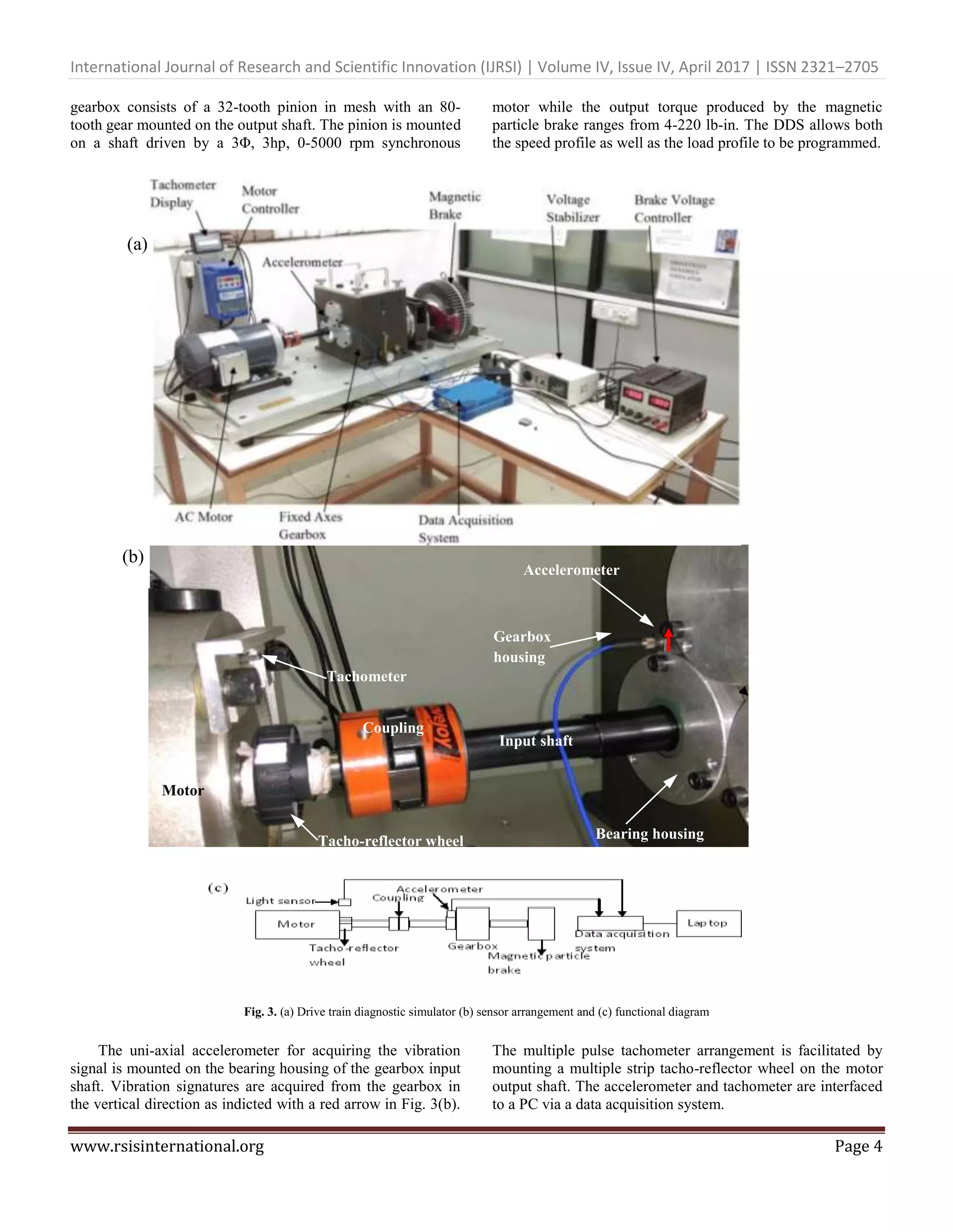
III. EXPERIMENTAL SET-UP AND DATA ACQUISITION
The experimental set-up consists of a single stage spur
gearbox that forms an integral part of the drive train
diagnostic simulator (DDS) shown in Fig. 3 (a). The DDS
Tacho-reflector
wheel
Reflective
strips
Light sensor
Motor output
shaft
36
47 7
Revolution 1
Revolution 2](https://image.slidesharecdn.com/01-08-170415075408/75/Gearbox-Fault-Diagnosis-using-Independent-Angular-Re-Sampling-Technique-Wavelet-Packet-Decomposition-and-ANN-3-2048.jpg)
![International Journal of Research and Scientific Innovation (IJRSI) | Volume IV, Issue IV, April 2017 | ISSN 2321–2705
www.rsisinternational.org Page 6
For effective fault diagnosis, useful features representing
the gearbox health condition must be extracted from the
acquired vibration signals.
IV. FEATURE EXTRACTION
Wavelet transform possesses good local property in both
time and frequency spaces [17]. However, the high frequency
bands where the modulation information of the machine fault
usually exists are not split in wavelet transform. Wavelet
packet transform, however, decomposes the approximations
(low frequency components) as well as the details (high
frequency components) resulting in frequency bands where
l is the level of decomposition. In the present work, the
gearbox vibration signals synchronized using the IAR
technique are split into a number of data samples consisting of
512 sampling points each. Each data sample is decomposed
with wavelet packet decomposition up to the third level
employing db1 as the wavelet basis function. Fig. 6 shows a
data sample extracted from the synchronized vibration signal
for the healthy pinion along with the 8 frequency bands and
the corresponding standard deviation values of wavelet packet
coefficients.
Fig. 6. A data sample from the synchronized vibration signal for the healthy pinion, the 8 frequency bands and standard deviation values of wavelet packet
coefficients
Since each data sample consists of 512 sampling points in the
angular domain, a maximum of 14 data samples are generated
from the synchronized angular domain vibration signal
pertaining to each gear health condition. Thus, 14 in number
eight-dimensional input feature vectors from each of the 4
classes, consisting of standard deviation values of wavelet
packet coefficients, are available to train and test the artificial
neural network.
V. ARTIFICIAL NEURAL NETWORK
One of the most commonly employed forms of artificial
neural networks (ANN) for fault diagnosis is the multilayer
perceptron (MLP) neural network trained with the back-
propagation algorithm. Such a neural network is shown in Fig.
7 and is also referred to as the back-propagation neural
network. In its simplest form, a back-propagation neural
network consists of an input layer, one or more hidden layers
and an output layer. The neurons in the different layers are
connected to each other with connecting links called synapses
and each such link is associated with a synaptic weight.
Fig. 7. Concept of multi-layer perceptron model
0 100 200 300 400 500
-6
-4
-2
0
2
4
6
8
sample number
acceleration(m/s
2
)
0 20 40 60
-10
0
10
0 20 40 60
-10
0
10
0 20 40 60
-5
0
5
0 20 40 60
-5
0
5
0 20 40 60
-5
0
5
0 20 40 60
-5
0
5
0 20 40 60
-2
0
2
0 20 40 60
-5
0
5
2.6770
1.6618
0.9764
1.1017
0.9584
1.2544
0.6597
0.8744
WPD STD](https://image.slidesharecdn.com/01-08-170415075408/75/Gearbox-Fault-Diagnosis-using-Independent-Angular-Re-Sampling-Technique-Wavelet-Packet-Decomposition-and-ANN-6-2048.jpg)
![International Journal of Research and Scientific Innovation (IJRSI) | Volume IV, Issue IV, April 2017 | ISSN 2321–2705
www.rsisinternational.org Page 7
The number of neurons in the input layer depends upon
the dimensionality of the input feature vectors and the number
of output neurons depends on the number of classes into
which the dataset is to be classified. The back-propagation
algorithm involves two passes – a forward pass and a
backward pass. In the forward pass, input features are
presented to the network in the form of vectors. This
information propagates in the forward direction and each
neuron in the output layer computes a value which may be
different from the desired output value. A mean squared error
(MSE) is then computed based on the difference between the
desired output and the target output. This information is
propagated in the backward direction. As the network is
trained, the synaptic weights are adjusted until the error
reaches a pre-defined value or another termination criterion is
met. Detailed information on the algorithm and other training
algorithms can be found in [18, 19].
The test accuracy of a back propagation neural network
consisting of 9 hidden neurons and employing the sigmoidal
activation function for the hidden and output neurons is
compared for two cases. In Case A, data samples consisting of
512 sampling points are extracted from the original time
domain vibration signal while in Case B, data samples
consisting of 512 sampling points are extracted from the
synchronized angular domain vibration signal. The present
work deals with a four-class gear fault identification problem
and hence there are only four output neurons. 50% of the
feature set in each case is used to train the neural network
while the remaining 50% is utilized to test its classification
accuracy.
VI. EXPERIMENTAL RESULTS AND DISCUSSIONS
In Case A, 14 data samples, each consisting of 512
sampling points, are extracted from the raw time domain
vibration signal pertaining to each gearbox health condition
resulting in a total of 56 data samples. In Case B, the data
samples are extracted from the angular domain vibration
signal synchronized using the IAR technique. Each data
sample in this case consists of 512 sampling points
representing 512 degrees of rotation of the gearbox drive
shaft. Each of the 56 data samples is decomposed with
wavelet packet decomposition up to the third level. Standard
deviation of the wavelet packet coefficients is then computed
and fed in the form of input feature vectors to an artificial
neural network. The percentage of correctly classified
instances from each class is shown in Table 1. 100% training
and test accuracy is obtained when data samples from the
synchronized vibration signals are employed for fault
diagnosis.
Table 1 Percentage of correctly classified instances for a fixed
ANN architecture
Percentage of correctly classified test instances
ANN
Architecture
8:9:4
Pinion Case A Case B
HEALTHY 85.7% 100%
CRACKED
TOOTH
60% 100%
CHIPPED
TOOTH
90% 100%
MISSING
TOOTH
83.3% 100%
VII. CONCLUSION
Uncertainties associated with the drive and load
mechanisms inevitably result in non-stationary conditions
even when the drive mechanism has been programmed to be
driven at a constant speed. The non-stationary vibration
signals collected from a single stage spur gearbox are
synchronized from the revolution point of view utilizing the
independent angular re-sampling (IAR) technique. The IAR
technique serves as a method to convert non-stationary signals
in the time domain into quasi-stationary signals in the angular
domain and demands only minor changes in hardware such as
the introduction of an additional tachometer reflective strip.
The classification accuracy of a back propagation neural
network is compared for features sets extracted from wavelet
packet decomposition of data samples in the time domain and
the angular domain. Superior gear fault diagnostic accuracy is
achieved when data samples extracted from the synchronized
vibration signal are employed for fault diagnosis. It is
concluded from this experiment that the IAR technique is a
simple yet powerful method of synchronizing the vibration
signal prior decomposition with wavelet packet transform.
The proposed method can be employed to diagnose faults in
rotating machineries under non stationary conditions with
reasonably good accuracy.
REFERENCES
[1]. H. Li, Y. Zhang, H. Zheng, Angle domain average and CWT for
fault detection of gear crack, in: Proceedings of the IEEE
Transaction, Fifth International Conference on Fuzzy Systems and
Knowledge Discovery 3, Jinan, Shandong, China, 2008, pp. 137-
141.
[2]. G. Meltzer, Y. Ivanov, Fault detection in gear drives with non-
stationary rotational speed - part I: the time-frequency approach,
Mech. Syst. Signal Process. 17 (2003) 1033-1047.
[3]. G. Meltzer, Y. Ivanov, Fault detection in gear drives with non-
stationary rotational speed - part II: the time-quefrency approach,
Mech. Syst. Signal Process. 17 (2003) 273-283.
[4]. H. H. Bafroui, A Ohadi, Application of wavelet energy and
Shannon entropy for feature extraction in gearbox fault detection
under varying speed conditions, Neurocomputing 133(2014) 437-
445.
[5]. H. Li, Y. Zhang, Gear fault detection and diagnosis under speed-
up condition based on order cepstrum and radial basis function
neural network, J. Mech. Sci. Technol. 23 (2009) 2780-2789.
[6]. M.A. Jafarizadeh, R. Hasannejad, M.M. Ettefagh, S. Chitsaz,
Asynchronous input gear damage diagnosis using time averaging
and wavelet filtering, Mech. Syst. Signal Process, 22 (2008) 172–
201.
[7]. N. Ahamed, Yogesh Pandya, A Parey, Spur gear tooth root crack
detection using time synchronous averaging under fluctuating
speed, Measurement 52 (2014) 1-11.
[8]. V. Sharma & A. Parey, Gear crack detection using modified TSA
and proposed fault indicators for fluctuating speed conditions,
Measurement, 90 (2016), 560–575.](https://image.slidesharecdn.com/01-08-170415075408/75/Gearbox-Fault-Diagnosis-using-Independent-Angular-Re-Sampling-Technique-Wavelet-Packet-Decomposition-and-ANN-7-2048.jpg)
![International Journal of Research and Scientific Innovation (IJRSI) | Volume IV, Issue IV, April 2017 | ISSN 2321–2705
www.rsisinternational.org Page 8
[9]. A. Singh & A. Parey, Gearbox fault diagnosis under fluctuating
load conditions with independent angular re-sampling technique,
continuous wavelet transform and multilayer perceptron neural
network, I. E. T. Science, Measurement and Technology, 2016.
[10]. Jian-Da Wu, Chiu-Hong Liu, An expert system for fault diagnosis
in internal combustion engines using wavelet packet transform and
neural network, Expert Systems with Applications 36 (2009)
4278-4286.
[11]. Yaguo Lei, Zhengjia He, Yanyang Zi, Application of an intelligent
classification method to mechanical fault diagnosis, Expert
Systems with Applications 36 (2009) 9941-9948.
[12]. Yaguo Lei, Ming J. Zuo, Zhengjia He, Yanyang Zi, A
multidimensional hybrid intelligent method for gear fault
diagnosis, Expert Systems with Applications 37 (2010) 1419-
1430.
[13]. Jian-Da Wu, Jian-Ji Chan, Faulted gear identification of a rotating
machinery based on wavelet transform and artificial neural
network, Expert Systems with Applications 36 (2009) 8862-8875.
[14]. J. Rafiee, F. Arvani, A. Harifi, M.H. Sadeghi, Intelligent condition
monitoring of a gearbox using artificial neural network, Mech.
Syst. Signal Process 21 (2007) 1746-1754.
[15]. J. Kang, X. Zhang, J. Zhao, H. Teng, D. Cao, Gearbox fault
diagnosis method based on wavelet packet analysis and support
vector machine, IEEE Conference on Prognostics and System
Health Management (PHM), 2012.
[16]. F.N. Fritsch, R.E. Carlson, Monotone piecewise cubic
interpolation, SIAM Journal of Numerical Analysis 14 (1980)
238-246.
[17]. Z. K. Peng, F. L. Chu, Application of wavelet transform in
machine condition monitoring and fault diagnostics: A review
with bibliography, Mech. Syst. Signal Process 18 (2003) 199-221.
[18]. B. Samanta, Gear fault detection using artificial neural networks
and support vector machines with genetic algorithms, Mech. Syst.
Signal Process 18 (2004) 625-644.
[19]. S. Haykin, “Neural Networks: A Comprehensive Foundation”,
second edition, Pearson Education, 1998.](https://image.slidesharecdn.com/01-08-170415075408/75/Gearbox-Fault-Diagnosis-using-Independent-Angular-Re-Sampling-Technique-Wavelet-Packet-Decomposition-and-ANN-8-2048.jpg)


![[IJET V2I5P7] Authors: Mr. Vaibhav A. Kalhapure, Dr.R.R.Navthar](https://cdn.slidesharecdn.com/ss_thumbnails/ijet-v2i5p7-161107140453-thumbnail.jpg?width=640&height=640&fit=bounds)


