This document summarizes a methodology for predicting stress corrosion crack growth rates when linear elastic fracture mechanics conditions are not met. The methodology relates crack tip opening angle to growth rate based on theoretical results under small-scale yielding, coupled with experimental data relating stress intensity factor to growth rate under LEFM conditions. It then predicts growth rates by determining crack tip opening angle under non-LEFM conditions. The paper analyzes a model of a solid with two deep cracks under tension to examine how plastic deformation extent and loading pattern (displacement or load control) affect predicted and LEFM-based growth rates throughout the plasticity range. It finds LEFM approaches can over or under-predict growth rates depending on conditions.

![214 E~ Smith
use the K approach as if they were operative. Alternatively one might use the K versus
dc/dt relation, convert it to a J versus dc/dt relation, and then determine J for the
situation under consideration. However, these approches do not satisfactorily address the
growth problem, and against this background the author [1] has developed a methodology
for predicting the growth rate of a stress corrosion crack when LEFM conditions are not
operative. The basis of the methodology is that a steady-state environmental condition is
assumed to exist in the vicinity of the crack tip and that the growth rate dc/dt depends on
the crack tip opening angle (CTOA); this latter assumption is essentially equivalent to a
correlation between growth rate and crack tip strain rate which has resulted from recenl
mechanistic studies [2,3] of the stress corrosion cracking process. A functional relation
between the CTOA and dc/dt is obtained by coupling theoretical results relating K with
the CTOA for crack growth in an inert environment under small-scale yielding conditions,
with the experimentally determined power law relation between the crack tip stress
intensity K and dc/dt for environmentally assisted crack growth under LEFM conditions.
Then, by assuming that the CTOA-dc/dt relation also applies to non-LEFM conditions
and by determining the CTOA for the non-LEFM situation under consideration, it is in
principle possible to predict the stress corrosion crack growth rate for that situation.
Earlier work [1], has focused on the model of an edge crack in a solid subjected to a
sufficiently high sustained stress that plastic deformation is extensive, though contained:
with this particular model, J increases during crack propagation. The growth rate
predicted by the aforementioned procedure was shown to be greater than that obtained by
application of the K versus dc/dt relation, its conversion to a J versus dc/dt correlation
and then the determination of J for the particular case under consideration; the predict-ions
are even more nonconservative if K values are determined at high stresses, assuming
that a K approach is directly applicable. There are a limited number of experimental data
suggesting that an LEFM approach underpredicts the growth rate at sustained high stress
levels, and thereby support the general conclusions of this early work's analysis. For
example, experiments [4] on iodine-induced stress corrosion cracks in internally pres-surized
Zircaloy tubes show that the measured KEscc value (the limiting threshold value of
K for growth) at close to yield stress levels is only one-third of the value as measured for
long cracks at low stress levels in DCB tests (LEFM conditions). By implication, it is
therefore expected that an LEFM approach underpredicts the growth rate at high stress
levels, in agreement with the early work's theoretical predictions.
In the earlier paper [1] it was suggested that the conclusion might have to be modified
for situations where J does not increase during crack growth, and this particular point has
been followed up in more recent work. Thus by inspecting the general relation between J
and crack growth rate that is obtained by the procedure, the author has focused [5] on the
extent to which experimental K-dc/dt data (supposedly obtained under LEFM condi-tions)
are unique with regard to loading mode: increasing K, constant K or decreasing K.
Uniqueness should be observed when the operative stress levels are low in relation to the
yield stress, and this is often the case with high yield stress materials [6]. On the other
hand, with low yield strength materials, it was shown that there ought to be differences in
the K-dc/dt data for different loading modes because strict LEFM conditions are not
really operative; the K-dc/dt curves should be higher for the increasing K loading mode
than for the decreasing K loading mode. It was suggested that this might be the case at
elevated temperatures when the' "effective" yield stress of a material is lowered by
time-dependent deformation. In this context, experimental evidence [7] for 304 stainless
steel tested in a corrosive environment at -300°C shows that the measured crack tip
stress intensity, for a given crack growth rate, is appreciably higher when experiments are
conducted in a decreasing K rather than an increasing K loading mode. Other recent
theoretical work [8] addressing the non-increasing J situation has considered the specific](https://image.slidesharecdn.com/precdictingcorrosioncrackratesgrowth-141104211418-conversion-gate02/85/Precdicting-corrosion-crack-rates-growth-2-320.jpg)
![Predicting stress corrosion crack growth rates 215
model: the plane strain deformation of a solid with two symmetrically situated deep
cracks, and with tension of the small remaining ligament, for the case where there is
general yield of the ligament. The loading points are situated on the central axis which
bisects the ligament and the relative displacement of the loading points is maintained at a
constant value during crack growth. With a plastic rigid model for the solid, J retains a
constant value during crack growth, and using the predictive procedure described in this
Introduction, it was shown that the LEFM procedure (i.e., direct usage of K values) in fact
overpredicts the crack growth rate in this particular situation.
From the theoretical work just described, which is supported to a limited extent by the
referenced experimental data, it is quite clear that as regards the growth rate of stress
corrosion cracks at high stress levels, the extent of plastic deformation and loading
pattern, i.e., displacement or load control, have a very significant effect on the degree of
conservatism of LEFM procedures, and this should be appreciated when using lifetime
prediction procedures. It is against this background that the present paper describes the
results of a general study of the model of a solid with two symmetrically situated deep
cracks, and with tension of the small remaining ligament. Using analytical results for the
magnitude of the J integral and the load point displacement, it is possible to examine the
effects of loading pattern and the extent of plastic deformation on the stress corrosion
crack growth rate, all the way through from small-scale yielding, extensive though
contained yield, to beyond general yield; the interplay between the degree of plastic
deformation and loading pattern can therefore be examined. Again the predictions are
compared with those obtained via the J - K - dc/dt correlation approach, and also with
those obtained on the basis that a K approach is directly applicable. The extent to which
these latter approches give conservative or nonconservative growth rate predictions are
discussed in relation to the extent of plastic deformation and loading pattern.
2. Preliminary theoretical background
Following earlier work by Rice and Sorensen [9], Rice, Drugan and Sham [10] (hereafter
referred to as RDS) have investigated the inert environment growth of a crack in a
non-work-hardening plastic elastic material, under mode I plane strain small-scale yielding
conditions. The results of an asymptotic analysis show that the crack tip stress state
approximates to the classic Prandtl field, and they obtain an expression for the opening
displacement at a distance r behind the growing crack tip. Coupling this expression with
the criterion that a critical opening 8 c be maintained at a small characteristic distance r m
behind the tip (S Jr m -O is essentially the crack tip opening angle CTOA defined with
respect to the measurement position rm), RDS derive a crack growth equation
d J %0 flOo2 [ rm ]
= + ln, / (1)
de a aE ~ -~
where c = crack length, a 0 = yield stress, E = Young's modulus, J denotes the far-field
value of the J integral, and fl is a constant having the value 5.08 when Poisson's ratio
~, = 0.3. The asymptotic analysis does not give the value of the parameter a, though
comparisons with finite element results suggest that a- 0.65 is approximately the same
for static and growing cracks. Furthermore, R was shown to scale approximately with the
plastic zone size, being about 15 to 30% larger, i.e., R = ~EJ/oo 2 with •- 0.23. RDS
argued that the growth condition (1), as well as being valid for the small-scale yielding
case, should also be valid for those highly constrained geometrical configurations where
the Prandtl field is likely to be maintained, e.g., for larger-scale contained yielding, and
also for some general yield states such as plane strain bending with a deep crack and for
tension of a solid with two symmetrically situated deep edge cracks (this particular model](https://image.slidesharecdn.com/precdictingcorrosioncrackratesgrowth-141104211418-conversion-gate02/85/Precdicting-corrosion-crack-rates-growth-3-320.jpg)
![216 E. Smith
will be considered in detail later in this paper), though the values of R and ~ may be
different for these various cases.
While the RDS growth criterion is based on a constant crack tip opening angle, RDS
have noted that the criterion is also equivalent to the requirement that all points closer
than a small characteristic distance r,,, above and below the crack tip should accumulate a
plastic strain equal to or greater than a critical value as the crack approaches. Further-more,
and most importantly from the present paper's perspective, a growth equation
similar to (1) is obtained if growth criteria analogous to those used in conjunction with the
RDS model are coupled with a Dugdale-Bilby-Cottrell-Swinden (DBCS)-type modeL.
[! l, 12] Thus, consider the general DBCS model, not necessarily restricted to the small-scale
yielding case, where the tensile stress within the line plastic zone ahead of a crack has the
value Y representative of the material's tensile yield stress. Irrespective of the plastic zone
size and any geometrical parameters inherent in the model, if as a criterion for continuing
crack growth it is required that a constant CTOA O, measured with regard to a distance t;,,
behind the tip, be maintained during growth, or it is required that a point within the line
plastic zone at a small characteristic distance r m accumulates a displacement 8, as the crack
approaches (this is Wnuk's final stretch criterion [13]), the ensuing differential equation
for crack growth is [13,141
dJ 4(1 - ~2) ln{ r,,_z, t
dc OY + ~-~ s [ {9),
with 0---3,/r,,,, while s is a distance parameter which depends on both the extent of
yielding and any geometrical parameters in the model, and enters into the expression for
the crack opening 6 at a distance r behind the tip of a stationary crack length of c:
4(1- ~2)Yrln( ~ )
~ = II)'['lP((') + ;E f~' (3)
where ~-Hp(C) is the crack tip displacement in the DBCS model. The similarities between
Eqns. (1) and (2) are obvious, with s in the DBCS model being analogous to R in the RDS
model; for the small-scale yielding situation s is linearly related to J and the plastic zone
size, as also is R in the RDS model. The final stretch criterion applied to the DBCS model
is analogous to the accumulated strain criterion for the RDS model, and has important
physical significance, since if r,, is envisaged to be the size of the fracture process zone
within which decohesion processes are operative, the criterion is equivalent to imposing
the condition that a critical number of dislocations be emitted into the material during the
fracture of a material element; such a criterion has obvious physical appeal. Though the
DBCS model is highly idealized, because the resulting growth equations are similar to
those obtained via the more realistic RDS model if analogous growth criteria are used. and
also because the concept of growth being associated with the emission of a critical number
of dislocations is physically reasonable, the idea of plastic growth being associated with a
constant CTOA, which is equivalent to the accumulation of a critical strain or the
emission of a critical number of dislocations per element of crack advance, has credibility.
Furthermore, use of the DBCS type model for investigating plastic crack growth would
appear to be justifiable, particularly for those geometrical configurations where high
constraint is maintained.
In extending the preceding model to stress corrosion crack growth, the author [1] has
proceeded from the basis that the magnitude of the crack tip opening angle (CTOA) 0,
which is governed by the detailed fracture processes operative within the immediate
vicinity of the crack tip~ is related to the growth rate v = dc/dt, with 0 decreasing as t::
decreases. RDS have also suggested that 0 decreases in the presence of an aggressive
environment, while a correlation between growth rate and CTOA is also essentiall'](https://image.slidesharecdn.com/precdictingcorrosioncrackratesgrowth-141104211418-conversion-gate02/85/Precdicting-corrosion-crack-rates-growth-4-320.jpg)
![Predicting stress corrosion crack growth rates 217
equivalent to the correlation between growth rate and crack tip strain rate that has
resulted from recent mechanistic studies [2,3] of the stress corrosion cracking process.
This follows as a result of the RDS conclusion that a CTOA criterion is equivalent to an
accumulated strain criterion. For then a CTOA-growth rate correlation implies an
accumulated strain-growth rate correlation, and if "~ is the accumulated strain, the strain
rate of the material near the crack tip is - yrm/v, whereupon it follows that there is a
correlation between the growth rate and the crack tip strain rate. In physical terms the
assumption of a correlation between 8 and v implies that crack advance is accompanied by
the emission of dislocations from the crack tip region into the surrounding material; the
more severe the environmental attack, and the more time that is allowed for this attack to
proceed (e.g., the lower the crack speed), the smaller will be the number of dislocations
emitted for each element of crack advance. Implicit in the use of a unique 8 - v relation is
the assumption that a steady-state environmental condition is maintained in the vicinity of
the crack tip during growth. If such a condition does not exist, the approach might have to
be modified appreciably, and this could involve the use of bounding procedures based on
specific environmental limits.
The governing relation between the CTOA and crack growth rate will now be obtained
by coupling the theoretical results relating the crack tip stress intensity K with the CTOA
for crack growth in an inert environment under small-scale yielding conditions, with the
experimentally determined power law relation between K and dc/dt for environmentally
assisted crack growth under LEFM conditions. In obtaining this relation the theoretical
results from the DBCS model will be used, since this type of model will be used later for
investigating the behavior of a solid with two symmetrically situated deep cracks. For
small-scale yielding, the parameter s in relation (2) is equal to [13,14] ~reEJ/2(1 - i, 2)y2 _
~reK2/2y 2 whereupon relation (2) becomes, after introduction of a/9 - v relation,
K2 2Y2rmexp{ ~rEO(v) -~r____K
~re ,4~-~ Y exp 2Y 2 -~c (4)
Relation (4) shows that K varies with crack speed; however, the K- v relation is unique
only if the expression within the second exponential bracket is small. This will be the case
at low applied stress levels as the following example clearly shows. [15] With a sustained
stress test where a constant stress o is applied to a semi-infinite solid containing an edge
crack of depth c, K - ova- and the term within the second exponential bracket is equal to
-'/r2o2//4Y 2, which is small if o << Y. In such cases, i.e., strict LEFM conditions, the
relation between the crack tip stress intensity K and the crack growth rate v = dc/dt
reduces to
K 2 - 2Ye2XrmP Tr e 4 0 _-- ;i-~ y
and the relation between K and dc/dt is then unique in the sense that it is independent of
the applied loadings and the crack size except, of course, through their coupled elects via
the K parameter. This result emphasizes the importance and usefulness of laboratory K
versus dc/dt data provided they are obtained under strict LEFM conditions. Such
experimental data generally display a constant growth rate stage II regime which is often
interpreted in terms of a controlling process involving the rate at which aggressive
chemical species affect the material in the crack tip region. This is preceded by the stage I
regime where, in contrast, there is a wide variation in crack growth rate for only a small
change in K. Within this stage I regime, the K- v relation assumes the form
v =AKm (6)
where A and m are constants. Stress corrosion crack growth is governed by this relation](https://image.slidesharecdn.com/precdictingcorrosioncrackratesgrowth-141104211418-conversion-gate02/85/Precdicting-corrosion-crack-rates-growth-5-320.jpg)
![Predicting stress corrosion crack growth rates 219
P' AT
< 2h ~-
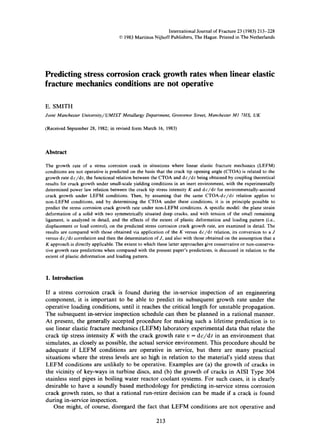
Figure 1. The plane strain model of a solid containing two symmetrically situated deep cracks. A load P is
applied to the solid at a great distance from the ligament, A being the load point displacement. The solid is
loaded in series with a linear spring of compliance C M such that the total load point displacement is
Ar=CMP + A.
load point displacement• The solid is loaded in series with a linear spring of compliance
CM, which can be identified with the testing machine compliance; the total load point
displacement is therefore A r = CMP + A. As indicated in the preceding section, this is a
highly constrained geometrical configuration where the Prandtl field is maintained, and
for which the RDS model, and thereby the simulation DBCS model, are especially
appropriate. The objective of this section's analysis is to use analytical expressions for
d J/dc and s, substitute them into (8), and consequently predict the stress corrosion crack
growth rate.
In analyzing the model, the results [16] for a periodic system of coplanar cracks in an
infinite solid will be used, the solid being cut along vertical surfaces so as to give the
model of a solid of total width 2h containing two symmetrically situated cracks of depth c,
the solid deforming under plane strain conditions due to the application of an applied
tensile stress o (this cutting procedure will be exact for the analogous mode III model)•
Using the DBCS representation of yield, the results [16] for the contained yield situation
show that s and J are given respectively by the expressions
[sin2(~-~ ) -sln'z{~re')(]J~ tan(~-~ )
s = 2ec (10)
• 2 { ~ra ~rc
and
j=8 ( l ~ ~ 2 ~ hYs i n ~ f / 2 cosx __ln sin(x -+- xI,) } dx (10
rr2E "* ~/1 - sin2a sin2x sin(x ~t')
where (a - c) = Rp is the size of the plastic zone at each crack tip and a = ~ra/2h is given
by the expression
sin(° )
sin a - cos = sin q' (12)](https://image.slidesharecdn.com/precdictingcorrosioncrackratesgrowth-141104211418-conversion-gate02/85/Precdicting-corrosion-crack-rates-growth-7-320.jpg)
![220 E. Smith
For the special case where the cracks are deep in comparison with the solid width,
relations (10) and (11) simplify to
2eL
s (13) (l+'y 2 )
and
J =8(1-v2)Y2L In + In ~ (14)
~rE ¢]+ y2 + 72 , Y
where 2 L is the ligament width and
(1-t) (15)
V'l - (1 - t) -~
with t being the ratio of the plastic zone size (R,) at each tip to half the ligament width
(L); thus, for small-scale yielding, t ~ 0 while "~ -~ ~, and t -~ 1 and "~ ~ 0 as the general
yield state is approached. Applying these results to the case where a load P is applied at a
point a great distance away from the ligament, and along the line of symmetry which
bisects the ligament (thickness B), relations (12)-(15) give
with
while
and
(17)
s = 2eL)t 2 (18)
J = 4(1 - v2)Y 2 u(X) : 4(1 - v2)y2L
erE wE [(1 + )k) In(1 + X) + (1 - X) ln(l -)k)] (19)
It should be noted that )t is small for small-scale yielding conditions while X = 1 at general
yield. Though relation (t9) gives J, it does not, however, give dJ/dc, since this depends
on the loading pattern; dJ/d¢ will now be determined.
The load point displacement A can be separated into elastic components AEL and Ap/
with AEL being that displacement which is produced by the load P when there is no plastic
deformation; AeL is equal to A- AeL. Similarly, the J integral can be separated into
elastic and plastic components JEL and Jm: Using the same dimensional arguments as
Paris, Ernst and Turner [17], ApL can be expressed in the equivalent functional forms
a~,~: LgIX ) t
X= f( ApL/L ) t (20)
where ~ = P/2BLY. It is possible to represent ApL in this simple functional form since L
and B are the only length parameters associated with the solid's geometry, if the load is
applied at a great distance from the ligament, and the ligament size is small. Now Jm can
be expressed in the form [17]
JPL- - fa'I 3P dApc 1 fa,,, OP A ....](https://image.slidesharecdn.com/precdictingcorrosioncrackratesgrowth-141104211418-conversion-gate02/85/Precdicting-corrosion-crack-rates-growth-8-320.jpg)
![Predicting stress corrosion crack growth rates 221
where A c is the crack area and 8A,. = - 2BSL, and consequently the second of relations
(20) gives
2 ] (22)
whereupon the first of relations (20) then gives
Jet. ag(a) [Xg(e)d e (23)
2LY 2 Jo
Thus, if
foXg(e)de = I(X)'
or (24)
d/(X)
g(X)= dX
Eqn. (23) reduces to
dl 21 JpL (X)
dX X LYX (25)
which integrates to give
X 2 fXJpL(e)de
I = ~ -1o ~5 (26)
Now expression (19) gives the value of the J integral, and because the elastic component
JeL is
4(1 -- v 2) y2LX2 (27)
JEL = rrE
it follows that the plastic component JVL is given by the expression
4(1 - vZ)y2L [(1 + 2~) ln(1 + )~) + (1 - )~) ln(1 - ),) -X 2 ] (28) JP L = "IrE
whereupon substitution in relation (26) gives
I 2(1 ~_;2)Y[3x2_( 1 +X)21n(1 +)l)_(l_X)21n(l_X)] (29)
and relations (20) and (24) give
dI 4(1-v2)yL[2~-(I+X)In(I+X)]
aPL=Lg(~)=Ldx = ~r2 + (1 +)~)In(1-2l) (30)
The elastic component AeL of the load point displacement of the solid is given by the
expression [ 18]
<_- ('-"'"
-7 %- (31)
whereupon the total load point displacement is given by relations (30) and (31) as
A r= CMP + AeL + AEL
= CMP+ 4(1 - wvE2 )yL [ 2X- (1 + X) ln(1 + X) + (1 - X) ln(l - X)]
+ [ ~ h - -4- I n (TrL) I ( 1E- ~ ) P (32)](https://image.slidesharecdn.com/precdictingcorrosioncrackratesgrowth-141104211418-conversion-gate02/85/Precdicting-corrosion-crack-rates-growth-9-320.jpg)
![222 E. Smith
Now if stress corrosion crack growth proceeds under constant total load point displace-ment
conditions, i.e., displacement control, then dAz/dL = O, or
dP PdC L. dAez
d ==0 t33)
with C c being given by relation (31), while
d~L~ = g(X) + L . +~,, (34)
using relation (30) and noting that X = P/2BLY. Elimination of dAez/dL between (33)
and (34) gives
[ ~Ldg(X)ldP
Qvt + (-l:: q P d X -d-£ +
and since relation (19) gives
- +d57 [1 =0 (35)
~rE dJ - u( )t ) + L + ~ ~-£
4(1 - v2)Y 2 dL
(36)
elimination of dP/dL between relations (35) and (36) gives
~rE dJ
4(1 - v2)Y 2 dc
~rE dJ
4(1 - v2)Y 2 dL
, dg( ~ ) PdC v ]
LX du(X) .(2t) +X du(x)
P dX [ XL dg(X)] dX
137)
whereupon substitution for the functions u ( )t ) and g ( )t ) via relations (19) and (30) gives
~rE dJ
4(1 - v2)Y 2 dc
-ln(1 - X2)
. { 1 +X ]• i l +X ~rE PdC, I
~'ln[l--i-L~)[2X-ln[l---Z~)~ 4(l_v2)y ~Tf]
+ (381
-Xln(l-Xa)-} 4(1-~Ez)Y-~( M+C~)j
With this expression for dJ/dc and with expression (18) for the parameter s, it is in
principle possible to determine the stress corrosion crack growth rate by making the
appropriate substitutions in the general growth equation (8).
Rather than determining the actual growth rate, however, it is more instructive to
compare the rate v with that velocity VKj (see Eqn. (9)) predicted on the basis of the power
law relation (6) and the K - J conversion formula, i.e.,
~reEJ exp 4(1 5ffZ)y2 dc
(39)
this result being obtained from relations (8) and (9). It then follows by substitution using](https://image.slidesharecdn.com/precdictingcorrosioncrackratesgrowth-141104211418-conversion-gate02/85/Precdicting-corrosion-crack-rates-growth-10-320.jpg)
![Predicting stress corrosion crack growth rates 223
(18). (19), (31), and (38) that
vKJJ (1 - X2)[(1 + X) ln(1 + ~,) + (1 - ~,) ln(1 -)~)]
-(In(1l-+~xJiJ2 (40)
× exp - l n ( 1 -X 2)-~ 2 ( 1 - p 2 ) ( c . + ca)
with C E being given by (31). This relation allows a comparison to be made between v and
v/<s for different loading patterns and for differing amounts of plastic deformation within
the contained yield regime. For small-scale yielding when ~ is small, it is immediately seen
that V/VKj tends to unity, irrespective of the specimen and machine compliances C a and
C M. This is entirely in accord with the viewpoint expressed in the preceding section, where
it was shown that the stress corrosion crack growth rate can be characterized by J(K) if
small-scale yielding conditions are operative.
As plastic deformation becomes more extensive though still contained, i.e., as X
increases, the effects of the various parameters on the predicted growth rate can be
assessed by expanding the right-hand side of (40) in powers of )~ whereupon it follows that
- - 1 = I + X 2 - )
t vKj j EB(CM + Ca)
+ (higher powers of X) (41)
Since vKj does not depend on d J/dc, inspection of relation (41) immediately shows that
the crack growth rate v for load control conditions (C g = o0), is greater than for
displacement control conditions (C g :x 0), even at the same J value (i.e., the same value of
), and in both cases is greater than the growth rate v~s predicted by the J approch. This
result accords with the comments in the Introduction, where it was indicated that the
author's earlier work [5] had shown that the J(K)- dc/dt curve should be higher for a
situation where J(K) increases with crack length than when J(K) decreases with crack
length. The effects become more marked as plastic deformation becomes progressively
more extensive. Thus, focusing on the constant load condition (C g = ~), relation (40)
reduces to
(42)
V~gj (1 - X2)[(1 + 2,) ln(1 + X) + (1 - X) ln(1 - X)]
and Table 1 shows the ratio v/v~g for various values of X - P/2LBY and the plastic zone
size Rp at each crack tip. Since m can be large, for example a value m = 8 has been
suggested [19] for intergranular stress corrosion cracking in type 304 stainless steel used in
boiling water reactor coolant pipes, the predicted crack growth rate v can be far in excess
of the growth rate VKS predicted by the K-J correlation procedure and will be even
greater if the K approach is used directly. Of course, for these load control conditions, in
the limiting case where X = 1 there is general yield across the intervening ligament, and
unstable non-environmentally-assisted failure will occur since the critical CTOA for
non-environmentally-assisted crack growth is attainable. These results for load control
conditions are in general accord with those obtained from the author's earlier analysis [1]
of the model of an edge crack in a semi-infinite solid subject to a sufficiently high
sustained stress that plastic deformation is extensive.
Relation (40) allows the effect of departing from load control conditions to be assessed
for different amounts of plastic deformation. Thus giving rrEBCe/2(1 -p2) the typical](https://image.slidesharecdn.com/precdictingcorrosioncrackratesgrowth-141104211418-conversion-gate02/85/Precdicting-corrosion-crack-rates-growth-11-320.jpg)
![224 E. Smith
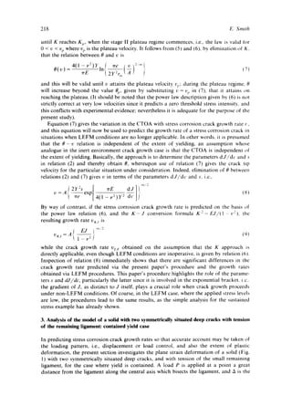
TABLE 1
The predicted crack growth rate for different amounts of plastic deformation under load control conditions
(C M = ~), and also for the displacement control conditions: C M = 0 and qrEBC E/2(1 -- v 2 ) = 5
p Rp
2LBY L
LOAD CONTROL DISP. CONTROl.
(_v)2 ..... (f )2 ,,,
~)KJ t']ffj
0.2 0.02 1.02 0.99
0.4 0.08 1.15 1.00
0.6 0.20 1.46 1.03
0.8 0.40 2.41 1.08
0.9 0.57 4.31 1.18
0.95 0.70 7.98 1.28
value of 5, this corresponding to D < h and h - IOL, and assuming a rigid test machine
(CM = 0), when crack growth proceeds as a result of a constant displacement applied to
the solid, relation (40) gives the predicted growth rate, which is shown in the last column
of Table 1. For this situation, although the predicted growth rate is still greater than the
growth rate VKj predicted by the K-J correlation procedure, with the effect becoming
greater as plastic deformation becomes more extensive, the effects are significantly less
than for the load control case.
4. Analysis of the model of a solid with two symmetrically situated deep cracks with tension
of the remaining ligament: post-general yield case
As indicted in the preceding section, with the non-work-hardening material examined in
the present study, stress corrosion crack growth under load control conditions gives way to
unstable non-environmentally-assisted failure when plastic deformation traverses the
ligament. Under displacement control conditions, however, it is possible for stress
corrosion crack growth to occur after general yield; this facet of the problem will now be
considered by extending the preceding section's analysis. As before, the solid is assumed
to be loaded in series with a linear spring, and the total load point displacement A r is
fixed during growth. For the general yield state, this displacement is given by the
expression
A T = CMP + ApL q- AEL q- AGy
8(1 =2LBYC~+ -~)~L 1[ -ln2]+ --In
IrE rr , ~ E
+Act (43)
where AeL is given by relation (30) with X = 1, i.e., it is the value of ApL just at general
yield, A EL is given by relation (31) with P having the general yield value 2 LB Y and A~; ~ is
the additional plastic contribution to the solid's load point displacement, due to the
post-general yield plastic deformation. The J integral now has the value
J = 8(1 - v2)y2L In 2
• rE + Y&(;r (44)
where the first term on the right-hand side is the value of J just at general yield and is
given by relation (19) with X = 1, while the second term is due to the additional plastic
displacement associated with the post-general yield deformation. Since dAT/dL = O, Eqn.](https://image.slidesharecdn.com/precdictingcorrosioncrackratesgrowth-141104211418-conversion-gate02/85/Precdicting-corrosion-crack-rates-growth-12-320.jpg)
![Predicting stress corrosion crack growth rates 225
(43) becomes, upon differentiation,
2BYCM+ 8(1- v2)Y [1-1n 2] + I D-~ln4 (-2-~rhL )I - EVZ)2Y
8(1 - vZ)Y+ dAor
erE dL = 0 (45)
while differentiation of (44) gives
dJ 8(1 - v2)Y 2 In 2 YdAor
~- - - (46)
dL = erE dL
Proceeding along similar lines to those of the preceding section, elimination of the
dAoy/dL term between relations (45) and (46) gives
~rE dJ ¢rEB(CM + CE)
=-41n2+ (47)
4(1 -/,2)y2 dc 2(1 - v 2)
where C E is again given by expression (31). With expression (47) for dJ/dc and with
s = 2eL for the general yield situation (see (18) with k = 1), the ratio of the growth rate v
to the velocity Vxg, predicted on the basis of the power law relation (6) and the K-J
conversion formula, is given by relations (39), (44) and (47) as
(D._.._]~2/_r n 1 exp (~EB2-(-~C--M--~ ;+ CE}) (48)
VKj] 32 1-~ 8(1-v2)LYln2
In this case, it is also instructive to make the comparison with the growth rate VLF,
predicted on the basis that the K approach is directly applicable, regardless of the fact that
LEFM conditions are not operative; noting that K = 2YI/-L/~r, relations (6), (8), (47) and
the knowledge that s = 2eL, gives
( v ]2/m =~-~2 ex p 7rEB(CM+CE) (49) ~LF] 2(1 -- V 2)
Where the general yield state is just attained (A6r = 0), relation (48) shows that for the
case where the test machine is rigid (CM=0) and for ~rEBCE/2(1- v2)=5, then
(V/VKj) 2/m = 6.70, which accords with the increasing values of this ratio as general yield
is approached (see the last column in Table 1). If the post-general yield deformation
becomes extensive (i.e., AGy increases), the ratio decreases and can become less than unity,
particularly if CE has a smaller value. In this case, the K-J correlation procedure is
conservative, in relation to the present paper's procedure, as regards its growth rate
predictions. Direct application of the K approach can also give conservative growth rate
predictions if C E becomes smaller (see relation 49). This conclusion is in accord with the
results from an earlier analysis [8] of the general yield state under displacement control
conditions where it was shown that (V/VLF) could be less than unity if a plastic rigid
solution was used for J.
5. Discussion
The present paper has used a crack tip opening angle procedure for predicting the growth
rate of a stress corrosion crack in situations where LEFM conditions are unlikely to be
operative. The procedure follows in a logical manner from established research on inert
environment crack growth, and is based on the assumption that the CTOA associated with
growth is uniquely related to the growth rate dc/dt, an assumption that is essentially](https://image.slidesharecdn.com/precdictingcorrosioncrackratesgrowth-141104211418-conversion-gate02/85/Precdicting-corrosion-crack-rates-growth-13-320.jpg)
![226 E. Smith
equivalent to the correlation between growth rate and crack tip strain rate that has arisen
[2,3] as a result of mechanistic studies of the stress corrosion cracking process. The
functional relation between the CTOA and dc/dt has been obtained in this paper by
coupling the theoretical results for plane strain crack growth under small-scale yielding
LEFM conditions (for an inert environment), with an experimentally determined power
law relation between the crack tip stress intensity K and the growth rate dc/dt in an
aggressive environment; however, the theoretical results could equally well be coupled
with any experimental correlation between K and dc/dt. Then, presuming that the
CTOA-dc/dt relation is independent of the extent of yielding, an assumption whose
analogue in the inert environment growth case is that the CTOA is independent of the
extent of yielding, it is in principle possible to predict the growth rate in situations where
LEFM conditions are no longer applicable.
A specific model: the plane strain deformation of a solid with two symmetrically
situated deep cracks, and with tension of the small remaining ligament, has been
investigated in detail, this being possible because simple analytical results are available for
the J integral and the plastic displacement, irrespective of the extent of yielding at the
crack tip. The effects of the extent of spread of plastic deformation and the loading
pattern (i.e., displacement or load controlled deformation), together with their interactive
effects, have therefore been explored in detail, the predicted growth rate being compared
with that obtained via application of the K-dc/dt experimental relation, its conversion to
a J-dc/dt relation, and then the determination of J; they have also been compared with
the growth rate determined on the assumption that a K approach is directly applicable.
The extent to which these latter approaches lead to nonconservative growth rate predict-ions
in relation to the extent of spread of plastic deformation and the loading pattern have
been discussed; the theoretical predictions have also been related to earlier theoretical
work, and correlated in a general manner with experimental results on the crack growth
rate at high stress levels (e.g., iodine stress corrosion cracking in Zircaloy tubes) [4] and
with results on the effect of the loading pattern on the crack growth rate (e.g., 304 stainless
steel in a corrosive environment). [7] There is, therefore, a direct, albeit very general, link
between this paper's theory and experimental results; on this basis, the theoretical work
could form the springboard for experimental programs designed to actually measure
growth rates and correlate them with the extent of spread of plastic deformation and
loading mode. when there would then be a quantitative, and more specific, check on the
theory.
In view of the importance of the conclusions that have been drawn from this
investigation, it is worth highlighting some qualifying comments. Firstly, and most
importantly, the methodology is based on the premise that a steady-state environmental
condition exists in the vicinity of the crack tip. As indicated in Section 2. if such a
condition does not exist, and whether or not this is the case could emerge from the
detailed experimental programs proposed in the preceding paragraph, the methodology
might have to be modified appreciably, and this could involve the use of bounding
procedures based on specific environmental limits. Secondly, the model investigated in
this paper has been analyzed via the highly idealized DBCS-type representation of plastic
deformation. Though there are good grounds, as discussed in Section 2, for believing that
its predictions have value, nevertheless this representation of plastic deformation does
have limitations, which have been emphasized by Rice. [20] It is therefore desirable that
more realistic theoretical approaches be used to support the simple approach developed in
this paper. Thirdly, the effects of work-hardening should be incorporated within the
methodology. The material behavior in the present study is non-work-hardening and.
though this leads to a simple analysis, there are obvious limitations. For example, it is not
immediately possible to draw conclusions regarding the growth of a stress corrosion crack](https://image.slidesharecdn.com/precdictingcorrosioncrackratesgrowth-141104211418-conversion-gate02/85/Precdicting-corrosion-crack-rates-growth-14-320.jpg)
![Predicting stress corrosion crack growth rates 227
under load control conditions after general yield, though this difficulty can be overcome in
an approximate manner by replacing the yield stress Y by an effective yield stress YEFF
which allows for work-hardening. In this way, the author has studied [21] load control
growth after general yield; not surprisingly, it has been shown that the growth rate can be
high in this situation. Fourthly, the effects of time-dependent deformation should also be
accounted for in a realistic manner. In the earlier work [5], this has been done in a very
simple way by assuming that the yield stress is reduced by time-dependent deformation
and an "effective" yield stress parameter employed. Not surprisingly, such deformation
can cause problems when searching for parameters to characterize creep crack growth, a
problem that is in some respects analogous to stress corrosion crack growth, and which
has received a preliminary study [22] along similar lines to those used in this paper.
Acknowledgments
This work has been conducted as part of the Electric Power Research Institute program on
environmentally-assisted fracture in nuclear materials, and the author thanks several
colleagues, especially Dr. R.L. Jones and Mr. J.D. Gilman, for valuable discussions in this
general problem area, and also for their encouragement.
References
[ 1 ] E. Smith, Materials Science and Engineering 55 (1982) 97.
[2] F.P. Ford, in Aspects of Fracture Mechanics in Pressure Vessels and Piping, Eds. S.S. Palusamy and S.G.
Sampath, ASME Pressure Vessels and Piping Conference, Orlando, Florida, U.S.A. (1982) 229.
[3] P.M. Scott and A.E. Truswell, in Aspects of Fracture Mechanics in Pressure Vessels and Piping, Eds. S.S.
Palusamy and S.G. Sampath, ASME Pressure Vessels and Piping Conference, Orlando, Florida, U.S.A.
(1982) 271.
[4] R.L. Jones, F.L. Yagee, R.A. Stoehr and D. Cubicciotti, Journal of Nuclear Materials 82 (1979) 26.
[5] E. Smith, paper accepted for publication in RES MECHANICA.
[6] H.R. Smith, D.E. Piper and F.K. Downey, Journal of Engineering Fracture Mechanics 1 (1968) 123.
[7] D.M. Norris, T.U. Marston, R.L. Jones and S.W. Tagart, EPRI Pressure Boundary Technology Programme,
Special Report NP-1540-SR (1980) 2.
[8] E. Smith, Materials Science and Engineering, 60 (1983) 185.
[9] J.R. Rice and E.P. Sorensen, Journal of Mechanics and Physics of Solids 26 (1978) 163.
[10] J.R. Rice, W.J. Drugan and T.L. Sham, in Proceedings of Twelfth National Symposium on Fracture
Mechanics, ASTM STP 700 (1980) 189.
[l 1] D.S. Dugdale, Journal of Mechanics and Physics 8 (1960) 100.
[12] B.A. Bilby, A.H. Cottrell and K.H. Swinden, Proceedings of the Royal Society A 262 (1963) 304.
[ 13] M.P. Wnuk, International Journal of Fracture 15 (1979) 553- 58 I.
[14] E. Smith, Journal of Engineering Materials and Technology 103 (1981) 148.
[15] E. Smith, in Advances in Fracture Research, Proc. 5th Int. Conf. on Fracture, Cannes, March 1981, D.
Francois (ed.), Pergamon, Oxford (1980) 1019.
[16] B.A. Bilby, A.H. Cottrell, E. Smith and K.H. Swinden, Proceedings of the Royal Society A279 (1964) 1.
[17] P.C. Paris, H. Ernst and C.E. Turner, in Fracture Mechanics: Twelfth Conference, ASTM STP 700, American
Society for Testing and Materials (1980) 338.
[18] J.R. Rice, in Mechanics and Mechanisms of Crack Growth, Proceedings of Conference at Cambridge, U.K.,
M.J. May, Ed., British Steel Corporation Physical Metalurgy Centre Publication (1974) 14.
[19] G.R. Egan and R.C. Cipolla, ASME Paper 78-MAT-23, American Society for Mechanical Engineers (1978).
[20] J.R. Rice, Discussion to Reference [3].
[21] E. Smith, unpublished work.
[22] R. Pilkington and E. Smith, Journal of Engineering Materials and Technology 102 (1980) 347.
R6sum6
On peut prb.dire la vitesse de croissance dc/dt d'une fissure de corrosion sous tension dans les cas o6 la th6orie
lin6aire et 61astique (LEFM) n'est pas applicable en se basant sur la relation que pr6sente dc/dt avec rangle](https://image.slidesharecdn.com/precdictingcorrosioncrackratesgrowth-141104211418-conversion-gate02/85/Precdicting-corrosion-crack-rates-growth-15-320.jpg)