Downloaded 21 times

![Sold & Serviced By:
Harmonic Drive LLC
800-921-3332
5
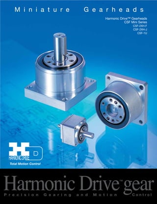
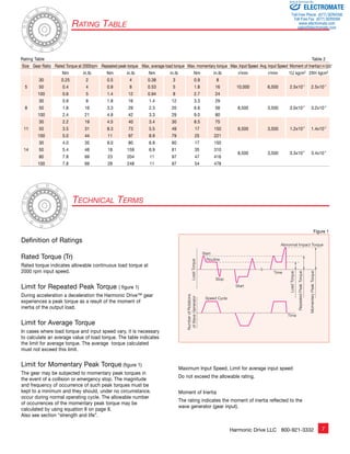
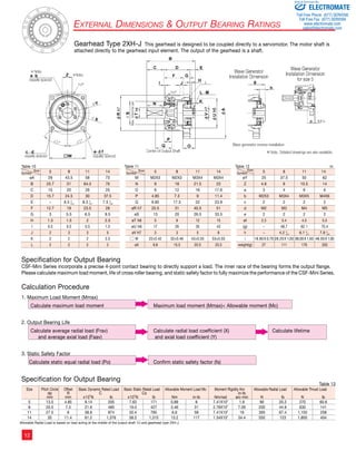
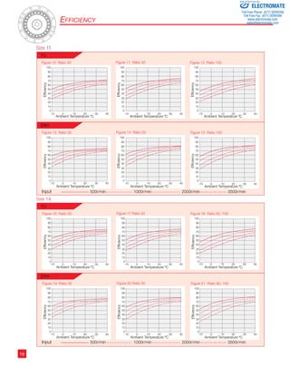
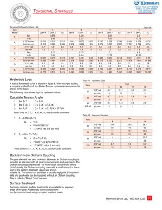
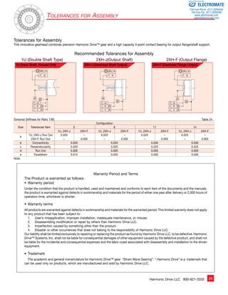
Driving Configurations
A variety of different driving
configurations are possible, as shown
below. The reduction ratio given in
the tables on page 10 and 11 correspond
to arrangement 1, in which the Wave
Generator acts as the input element,
the Circular Spline is fixed and the
Flexspline acts as the output element.
Ratio =
input speed
output speed
3. Reduction Gearing
WG Fixed
FS Input
CS Output
R + 1
Ratio = R [Equation 3]
Input and output in same direction.
6. Speed Increaser Gearing
FS Fixed
CS Input
WG Output
1
Ratio = R + 1 [Equation 6]
Input and output in same direction.
WG
CS
FS
1. Reduction Gearing
CS Fixed
WG Input
FS Output
Ratio = — R 1
[Equation 1]
Input and output in opposite direction.
4. Speed Increaser Gearing
WG Fixed
CS Input
FS Output
R
Ratio = R + 1 [Equation 4]
Input and output in same direction.
7. Differential Gearing
WG Control Input
CS Main Drive-Input
FS Main Drive-Output
Numerous differential functions can
be obtained by combinations of the
speed and rotational direction of
the three basic elements.
2. Reduction Gearing
FS Fixed
WG Input
CS Output
R + 1
Ratio = 1 [Equation 2]
Input and output in same direction.
5. Speed Increaser Gearing
CS Fixed
FS Input
WG Output
Ratio = — 1 R
[Equation 5]
Input and output in opposite direction.
Driving Configurations
[Equation 7]
ELECTROMATE
Toll Free Phone (877) SERVO98
Toll Free Fax (877) SERV099
www.electromate.com
sales@electromate.com](https://image.slidesharecdn.com/harmoniccsfminicatalog-141008202240-conversion-gate02/85/Harmonic-csf-mini_catalog-5-320.jpg)
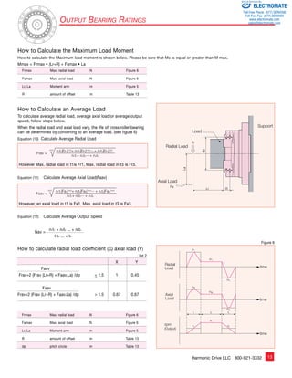
![Table 3 Ratcheting Torque Nm Buckling Torque Nm
8
17
16
10
9
8
7
6
5
4
3
2
1
Sold & Serviced By:
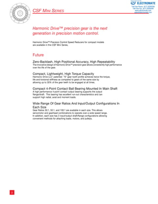
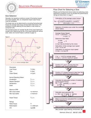
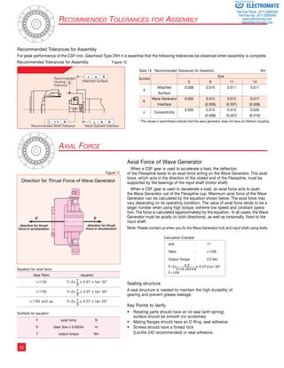
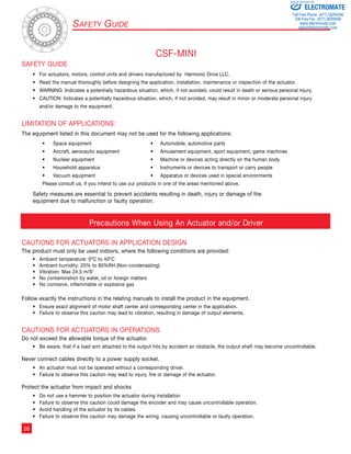
Figure 2
Buckling Torque
Racheting Torque
Circular Spline
Flexspline
Momentary Peak Torque
105 106 107 108 109 0
Load Torque ( Rated Torque = 1 )
Total Number of Input Rotations
1010
Life of the Wave Generator
Fatigue Strength of Flexspline
Repeated Peak Torque
Rated Torque
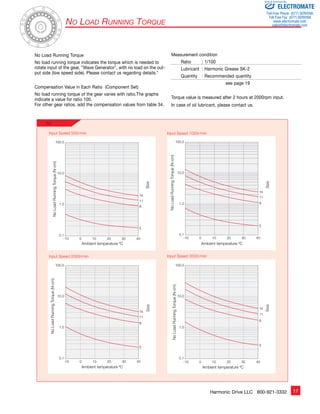
Strength and Life
The non-rigid Flexspline is subjected to repeated deflections, and its
strength determines the torque capacity of the Harmonic Drive™ gear.
The values given for Rated Torque at Rated Speed and for the allow-able
Repeated Peak Torque are based on an infinite fatigue life for the
Flexspline.
The torque that occurs during a collision must be below the momentary
peak torque (impact torque). The maximum number of occurrences is
given by the equation below.
Ratcheting phenomenon
When excessive torque is applied while the gear is in motion, the teeth
between the Circular Spline and Flexspline may not engage properly.
This phenomenon is called ratcheting and the torque at which this
occurs is called ratcheting torque. Ratcheting may cause the Flexspline
to become non-concentric with the Circular Spline.
(See figure 2 and 3 on page 8) Operating in this condition may result
in shortened life and a Flexspline fatigue failure.
Note!
When ratcheting occurs, the teeth mesh abnormally as shown above.
Vibration and Flexspline damage may occur. Once ratcheting occurs,
the teeth wear excessively and the ratcheting torque may be lowered.
The Life of a Wave Generator
The normal life of a gear is determined by the life of the wave genera-tor
bearing. The life may be calculated by using the input speed and the
output load torque.
Rated Lifetime Ln : (n = 10 or 50)
L10 CSF : 7,000 CSG: 10,000
L50 CSF : 35,000 CSG : 50,000
Equation for the expected life of the wave generator under
normal operating conditions is given by the equation below.
[Equation 9]
Lh = Ln • ( Tr )3• ( Nr )
Tav Nav
Lh : Expected Life, hours
Ln : Rated Lifetime at L10 or L50
Tr : Rated Torque (Table 2)
Nr : Rated input speed (2000 rpm)
Tav : Average load torque on output side (page 9)
Nav : Average input speed (page 9)
[Equation 8]
1.0 X 10⁴ n: Input speed before collision
N =
2 X n X t t: Time interval during collision 60
Please note:
If this number is exceeded, the Flexspline
may experience a fatigue failure.
This condition is called “dedoidal”.
Relative Torque Rating
The chart below shows the various torque specifications
relative to rated torque. Rated Torque has been
normalized to 1 for comparison.
Size Gear Ratio
Size All Ratio
30 50 80 100
5 2.7 3.2 – 3.5 5 9.8
8 11 12 – 14 8 35
11 29 34 – 43 11 90
14 59 88 110 84 14 190
Figure 3
Strength and Life
ELECTROMATE
Toll Free Phone (877) SERVO98
Toll Free Fax (877) SERV099
www.electromate.com
sales@electromate.com](https://image.slidesharecdn.com/harmoniccsfminicatalog-141008202240-conversion-gate02/85/Harmonic-csf-mini_catalog-8-320.jpg)
![Sold Serviced By:
ELECTROMATE
Toll Free Phone (877) SERVO98
Toll Free Fax (877) SERV099
www.electromate.com
sales@electromate.com
Harmonic Drive LLC 800-921-3332 19
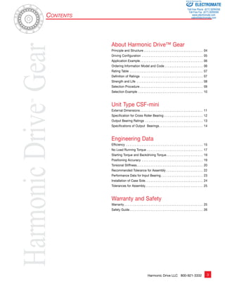
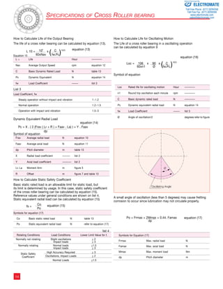
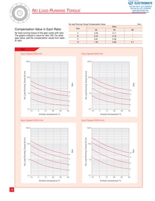
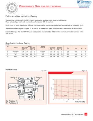
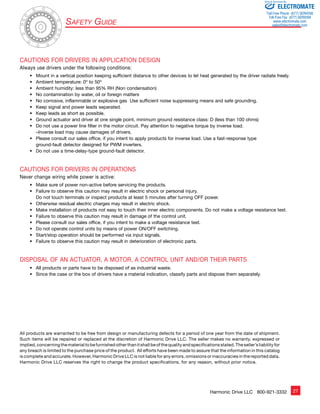
Starting Torque
Starting torque is the torque required to commence rotation of the
input element (high speed side), with no load being applied to the
output. The table below indicates the maximum values. The lower
values are approximately 1/2 to 1/3 of the maximum values.
Temperature is at 20 degree C.
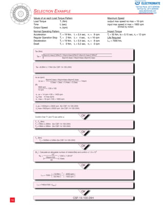
Positioning Accuracy
The positioning accuracy of the gear represents a linearity error
between the input and output angle. The position error is the
difference between theoretical and actual output rotation angle.
The positioning accuracy is measured for one complete output
revolution using a high resolution measurement system. The
measurements are carried out without reversing direction.
The positioning accuracy is defined as the difference between
the maximum positive and maximum negative deviation from
the theoretical position.
Typical Positional Accuracy Curve
Component Type Backdriving Torque
Backdriving torque is the torque required to commence
rotation of input element (high speed side) when torque
is applied on the output side (low speed side). The table
below indicates the maximum values. The typical values
are approximately 1/2 to 1/3 of the maximum values. The
backdriving torque should not be relied upon to provide
a holding torque to prevent the output from backdriving.
A failsafe brake should be used for this purpose.
Measurement condition: Ambient temperature 20ºC
Values shown below vary depending on condition.
Please use values as a reference.
θer........................................ Positioning Accuracy
θ1......................................... Input Angle
θ2......................................... Actual Output Angle
R.......................................... Gear Ratio ( i=l;R )
θer = θ2 – θ1 equation [18]
R
øer
Starting Torque and Backdriving Torque
Starting Torque Ncm
Size
Ratio
30 50 80 100
5 0.53 0.40 – 0.30
8 1.3 0.80 – 0.59
11 3.4 2.0 – 1.5
14 6.4 4.1 2.8 2.5
Positioning Accuracy arc-min
Ratio
Size
5 8 11 14
30 4 2 2 2
50+ 3 2 1.5 1.5
Back Driving Torque Nm
Size
Ratio
30 50 80 100
5 0.29 0.21 – 0.27
8 0.70 0.55 – 0.75
11 1.7 1.2 – 1.5
14 2.4 1.6 1.6 1.8](https://image.slidesharecdn.com/harmoniccsfminicatalog-141008202240-conversion-gate02/85/Harmonic-csf-mini_catalog-19-320.jpg)

This document provides information about Harmonic Drive gearheads, including the CSF Mini Series. It describes the principle and structure of Harmonic Drive gears, including the wave generator, flexspline, and circular spline components. It also includes specifications, dimensions, performance data, and engineering information about the CSF Mini Series gearheads.


![5G Explained! A High Level Overview [Introduction]](https://cdn.slidesharecdn.com/ss_thumbnails/5gexplainedahighleveloverview-260119165306-cc137a3e-thumbnail.jpg?width=640&height=640&fit=bounds)


