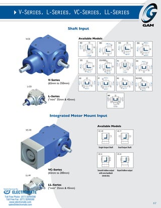
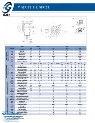
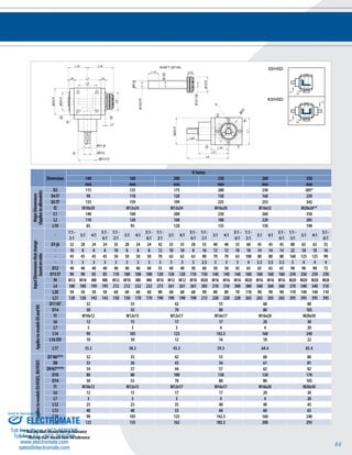
Download to read offline


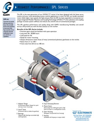
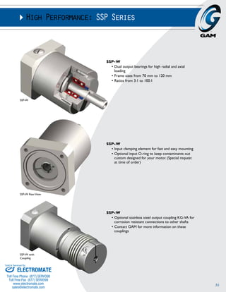
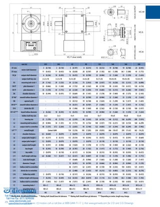
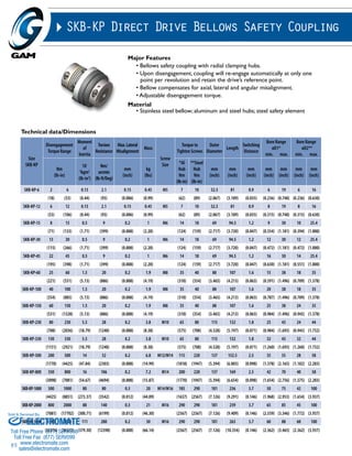
![10
SPH-W
TYPE CODES FOR SPL SERIES (SPH-W)
Example: SPH - W - 075 - 005 G - [115 - A01] - S111
Gearbox Series
SPL Series
Special Options
Assigned by GAM
Motor Mount Kit
Assigned by GAM
Gearbox Style
W = Output Shaft
Gearbox Size
050, 060, 075, 100, 140, 180
Ratio
3, 4, 5, 7, 10, 12, 15, 16, 20, 25, 28,
30, 35, 40, 50, 70, 100
Options Available for This Product
G = Key on output shaft per DIN6885
C = Reduced backlash and key on
output shaft
H = Smooth output shaft
A = Reduced backlash and smooth
shaft
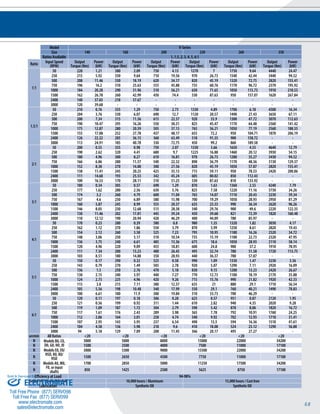
SPH-W
50 60 75 100 140 180
mm (in) mm (in) mm (in) mm (in) mm (in) mm (in)
D1max Standard
Motor Shaft Diameter
11 (0.433) 14 (0.551) 19 (0.748) 24 (0.945) 32 (1.260) 38 (1.496)
D1max Available1 11 (0.433) 19 (0.748) 24 (0.945) 32 (1.260) 38 (1.496) 48 (1.890)
D1max 2-stage 11 (0.433) 14 (0.551) 19 (0.748) 24 (0.945) 32 (1.260) 38 (1.496)
D2 k6 Output Shaft Diameter 14 (0.551) 16 (0.630) 22 (0.866) 32 (1.260) 40 (1.575) 55 (2.165)
D3 g6 Pilot Diameter 45 (1.772) 60 (2.362) 70 (2.756) 90 (3.543) 130 (5.118) 160 (6.299)
D4 Output Bolt Circle 63 (2.480) 68 (2.677) 85 (3.346) 120 (4.724) 165 (6.496) 215 (8.465)
f1 Mounting Holes 5.5 (0.217) 6 (0.236) 6.6 (0.260) 9 (0.354) 11 (0.433) 13 (0.512)
f2 Shaft End Thread M5 M5 M8 M8 M16 M20
L12 Overall Gearbox
Length
125 (4.921) 150 (5.906) 165 (6.496) 220 (8.661) 280 (11.024) 330 (12.992)
L1 2-stage
2 165 (6.496) 190 (7.480) 210 (8.268) 270 (10.630) 345 (13.583) 420 (16.535)
L2 Shaft Length 38 (1.496) 48 (1.890) 56 (2.205) 88 (3.465) 112 (4.409) 112 (4.409)
L3 Pilot Height 12 (0.472) 18 (0.709) 18 (0.709) 28 (1.102) 27 (1.063) 27 (1.063)
L4 Usable Shaft Length 24 (0.945) 28 (1.102) 36 (1.417) 58 (2.283) 82 (3.228) 82 (3.228)
L5 Flange Thickness 6 (0.236) 6 (0.236) 7 (0.276) 10 (0.394) 12 (0.472) 18 (0.709)
L6 Output Square 55 (2.165) 61 (2.402) 75 (2.953) 100 (3.937) 140 (5.512) 180 (7.087)
L72 Input Square 65 (2.559) 75 (2.953) 90 (3.543) 120 (4.724) 150 (5.906) 210 (8.268)
L8 Key Length 20 (0.787) 25 (0.984) 32 (1.260) 50 (1.969) 70 (2.756) 70 (2.756)
L9 Key Height 16 (0.630) 18 (0.709) 24.5 (0.965) 35 (1.378) 43 (1.693) 59 (2.323)
L10 Key Width 5 (0.197) 5 (0.197) 6 (0.236) 10 (0.394) 12 (0.472) 16 (0.630)
L11 Key End 2 (0.079) 1.5 (0.059) 2 (0.079) 4 (0.157) 5 (0.197) 6 (0.236)
Tolerance (mm)
Size k6 g6
Over 6 +0.010 -0.005
Thru 10 +0.001 -0.014
Over 10 +0.012 -0.006
Thru 18 +0.001 -0.017
Over 18 +0.015 -0.007
Thru 30 +0.002 -0.020
Over 30 +0.018 -0.009
Thru 50 +0.002 -0.025
Over 50 +0.021 -0.010
Thru 80 +0.002 -0.029
Over 80 +0.025 -0.012
Thru 120 +0.003 -0.034
Over 120 +0.028 -0.014
Thru 180 +0.003 -0.037
1) For larger motor shaft diameters, please contact GAM.
2) Depending on the motor, value can vary.
Sold & Serviced By:
ELECTROMATE
Toll Free Phone (877) SERVO98
Toll Free Fax (877) SERV099
www.electromate.com
sales@electromate.com](https://image.slidesharecdn.com/gamcatalog-141001201524-phpapp01/85/Gam-catalog-10-320.jpg)
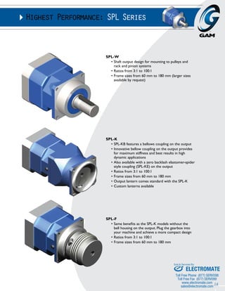
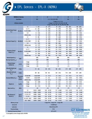
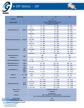
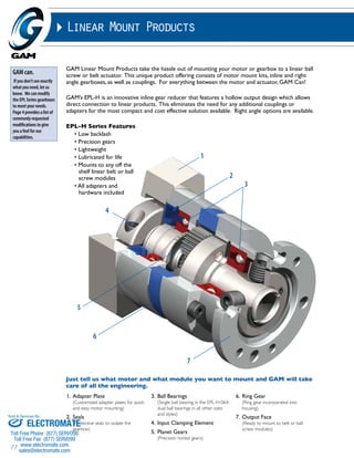
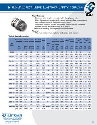
![12
SPH-K
TYPE CODES FOR SPH-K SERIES
Example: SPH - KE - 060 - 005 G - [115 - 201] - S111
Gearbox Series
SPH Series
Special Options
Assigned by GAM
Motor Mount Kit
Assigned by GAM
Gearbox Style
KB = Bellows coupling output
KE = Elastomer coupling output
Gearbox Size
050, 060, 075, 100, 140, 180
Ratio
3, 4, 5, 7, 10, 12, 15, 16, 20, 25, 28, 30,
35, 40, 50, 70, 100
Options Available for This Product
G = Standard backlash and keyway
in output coupling
C = Reduced backlash and keyway
in output coupling
H = Standard backlash and no keyway
in output coupling
A = Reduced backlash and no keyway
in output coupling
Tolerance (mm)
Size k6 g6
Over 6 +0.010 -0.005
Thru 10 +0.001 -0.014
Over 10 +0.012 -0.006
Thru 18 +0.001 -0.017
Over 18 +0.015 -0.007
Thru 30 +0.002 -0.020
Over 30 +0.018 -0.009
Thru 50 +0.002 -0.025
Over 50 +0.021 -0.010
Thru 80 +0.002 -0.029
Over 80 +0.025 -0.012
Thru 120 +0.003 -0.034
Over 120 +0.028 -0.014
Thru 180 +0.003 -0.037
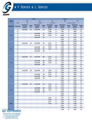
SPH-K
50 60 75 100 140 180
mm (in) mm (in) mm (in) mm (in) mm (in) mm (in)
D1max Standard
Motor Shaft Diameter
11 (0.433) 14 (0.551) 19 (0.748) 24 (0.945) 32 (1.260) 38 (1.496)
D1max Available1 11 (0.433) 19 (0.748) 24 (0.945) 32 (1.260) 38 (1.496) 48 (1.890)
D1max 2-stage 11 (0.433) 14 (0.551) 19 (0.748) 24 (0.945) 32 (1.260) 38 (1.496)
D2FB min Minimum Output
Bore
10 (0.394) 12 (0.472) 22 (0.866) 22 (0.866) 42 (1.654) 50 (1.969)
D2FE min 12 (0.472) 18 (0.709) 22 (0.866) 35 (1.378) 38 (1.496) 48 (1.890)
D2FB max Maximum Output
Bore
20 (0.787) 28 (1.102) 38 (1.496) 50 (1.969) 64 (2.520) 90 (3.543)
D2FE max 19 (0.748) 26 (1.024) 33 (1.299) 42 (1.654) 56 (2.205) 70 (2.756)
D3 g6 Pilot Diameter 55 (2.165) 70 (2.756) 85 (3.346) 115 (4.528) 135 (5.315) 180 (7.087)
D4 Output Bolt Circle 70 (2.756) 85 (3.346) 105 (4.134) 140 (5.512) 165 (6.496) 215 (8.465)
f1 Mounting Holes 5.5 (0.217) 6.6 (0.260) 9 (0.354) 11 (0.433) 13 (0.512) 17 (0.669)
L12 Overall Gearbox
Length
155 (6.102) 189 (7.441) 214 (8.425) 262 (10.315) 308 (12.126) 386 (15.197)
L1 2-stage
2 195 (7.677) 229 (9.016) 259 (10.197) 312 (12.283) 373 (14.685) 476 (18.740)
L2 Pilot Height 6 (0.236) 6 (0.236) 8 (0.315) 10 (0.394) 12 (0.472) 15 (0.591)
L3 Flange Thickness 6 (0.236) 7 (0.276) 9 (0.354) 11 (0.433) 13 (0.512) 15 (0.591)
L4 Output Square 60 (2.362) 70 (2.756) 95 (3.740) 120 (4.724) 145 (5.709) 190 (7.480)
L52 Input Square 65 (2.559) 75 (2.953) 90 (3.543) 120 (4.724) 150 (5.906) 210 (8.268)
t1FB min Minimum Shaft
Engagement
24 (0.945) 27 (1.063) 39.5 (1.555) 44 (1.732) 49 (1.929) 65.5 (2.579)
t1FE min 21 (0.827) 29 (1.142) 38.5 (1.516) 45 (1.772) 49 (1.929) 70 (2.756)
t1FB max Maximum Shaft
Engagement
41 (1.614) 51 (2.008) 62 (2.441) 74 (2.913) 86 (3.386) 105 (4.134)
t1FE max 27.5 (1.083) 36.5 (1.437) 46 (1.811) 55 (2.165) 60 (2.362) 83 (3.268)
1) For larger motor shaft diameters, please contact GAM.
2) Depending on the motor, value can vary.
Sold & Serviced By:
ELECTROMATE
Toll Free Phone (877) SERVO98
Toll Free Fax (877) SERV099
www.electromate.com
sales@electromate.com](https://image.slidesharecdn.com/gamcatalog-141001201524-phpapp01/85/Gam-catalog-12-320.jpg)

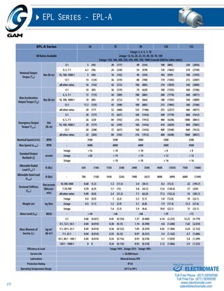
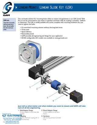
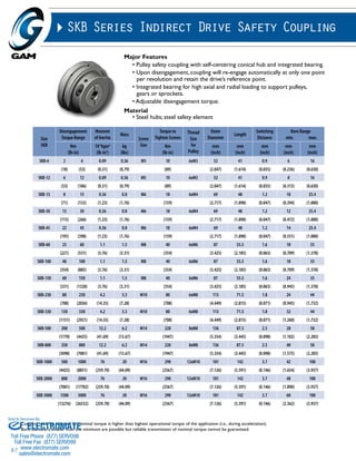
![14
Tolerance (mm)
Size k6 g6
Over 6 +0.010 -0.005
Thru 10 +0.001 -0.014
Over 10 +0.012 -0.006
Thru 18 +0.001 -0.017
Over 18 +0.015 -0.007
Thru 30 +0.002 -0.020
Over 30 +0.018 -0.009
Thru 50 +0.002 -0.025
Over 50 +0.021 -0.010
Thru 80 +0.002 -0.029
Over 80 +0.025 -0.012
Thru 120 +0.003 -0.034
Over 120 +0.028 -0.014
Thru 180 +0.003 -0.037
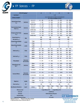
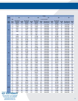
SPH-F
SPH-F
50 60 75 100 140 180
mm (in) mm (in) mm (in) mm (in) mm (in) mm (in)
D1max Standard
Motor Shaft Diameter
11 (0.433) 14 (0.551) 19 (0.748) 24 (0.945) 32 (1.260) 38 (1.496)
D1max Available1 11 (0.433) 19 (0.748) 24 (0.945) 32 (1.260) 38 (1.496) 48 (1.890)
D1max 2-stage 11 (0.433) 14 (0.551) 19 (0.748) 24 (0.945) 32 (1.260) 38 (1.496)
D2FB min Minimum Output Bore
10 (0.394) 12 (0.472) 22 (0.866) 22 (0.866) 42 (1.654) 50 (1.969)
D2FE min 12 (0.472) 18 (0.709) 22 (0.866) 35 (1.378) 38 (1.496) 48 (1.890)
D2FB max Maximum Output Bore
20 (0.787) 28 (1.102) 38 (1.496) 50 (1.969) 64 (2.520) 90 (3.543)
D2FE max 19 (0.748) 26 (1.024) 33 (1.299) 42 (1.654) 56 (2.205) 70 (2.756)
D3 g6 Pilot Diameter 45 (1.772) 60 (2.362) 70 (2.756) 90 (3.543) 130 (5.118) 160 (6.299)
D4 Output Bolt Circle 63 (2.480) 68 (2.677) 85 (3.346) 120 (4.724) 165 (6.496) 215 (8.465)
f1 Mounting Holes 5.5 (0.217) 6 (0.236) 6.6 (0.260) 9 (0.354) 11 (0.433) 13 (0.512)
L1FB2
Overall Gearbox
Length
144 (5.669) 177 (6.969) 197 (7.756) 244 (9.606) 283 (11.142) 356 (14.016)
L1FE2 151 (5.945) 180 (7.087) 202 (7.953) 248 (9.764) 292 (11.496) 354 (13.937)
L1FB 2-stage
2 184 (7.244) 217 (8.543) 242 (9.528) 294 (11.575) 348 (13.701) 446 (17.559)
L1FE 2-stage
2 191 (7.520) 220 (8.661) 247 (9.724) 298 (11.732) 357 (14.055) 444 (17.480)
L2FB
Coupling Length
57 (2.244) 75 (2.953) 88 (3.465) 112 (4.409) 115 (4.528) 138 (5.433)
L2FE 64 (2.520) 78 (3.071) 93 (3.661) 116 (4.567) 124 (4.882) 136 (5.354)
L3 Pilot Height 12 (0.472) 18 (0.709) 18 (0.709) 28 (1.102) 27 (1.063) 27 (1.063)
L4 Flange Thickness 6 (0.236) 6 (0.236) 7 (0.276) 10 (0.394) 12 (0.472) 18 (0.709)
L5 Output Square 55 (2.165) 61 (2.402) 75 (2.953) 100 (3.937) 140 (5.512) 180 (7.087)
L62 Input Square 65 (2.559) 75 (2.953) 90 (3.543) 120 (4.724) 150 (5.906) 210 (8.268)
t1FB min Minimum Shaft
Engagement
13 (0.512) 16 (0.630) 22 (0.866) 26 (1.024) 24 (0.945) 35.5 (1.398)
t1FE min 17 (0.669) 20 (0.787) 26.5 (1.043) 31 (1.220) 33 (1.299) 38 (1.496)
t1FB max Maximum Shaft
Engagement
30 (1.181) 39 (1.535) 45 (1.772) 56 (2.205) 61 (2.402) 75.5 (2.972)
t1FE max 23.5 (0.925) 27.5 (1.083) 34.5 (1.358) 41 (1.614) 44 (1.732) 51 (2.008)
TYPE CODES FOR SPH-F SERIES
Example: SPH - FE - 060 - 005 G - [115 - 201] - S111
Gearbox Series
SPH Series
Special Options
Assigned by GAM
Motor Mount Kit
Assigned by GAM
Gearbox Style
FB = Bellows coupling output
FE = Elastomer coupling output
Gearbox Size
050, 060, 075, 100, 140, 180
Ratio
3, 4, 5, 7, 10, 12, 15, 16, 20, 25, 28, 30,
35, 40, 50, 70, 100
Options Available for This Product
G = Standard backlash and keyway
in output coupling
C = Reduced backlash and keyway
in output coupling
H = Standard backlash and no keyway
in output coupling
A = Reduced backlash and no keyway
in output coupling
1) For larger motor shaft diameters, please contact GAM.
2) Depending on the motor, value can vary.
Sold & Serviced By:
ELECTROMATE
Toll Free Phone (877) SERVO98
Toll Free Fax (877) SERV099
www.electromate.com
sales@electromate.com](https://image.slidesharecdn.com/gamcatalog-141001201524-phpapp01/85/Gam-catalog-14-320.jpg)

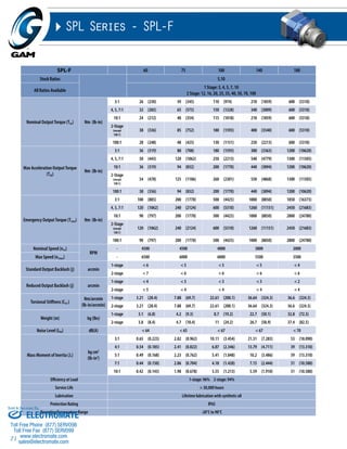
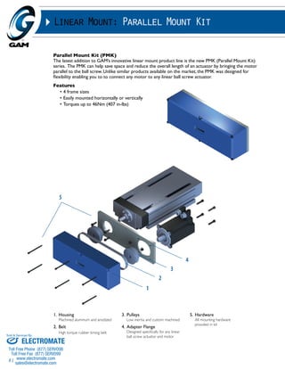
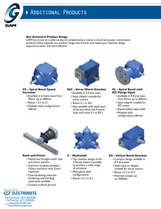
![18
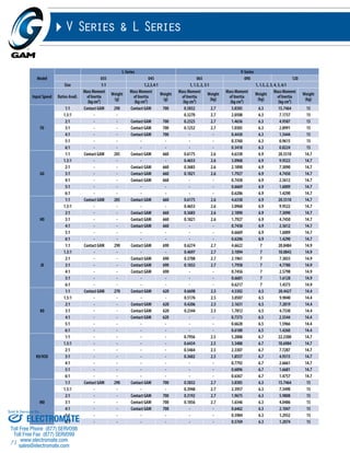
SPL-W
60 75 100 140 180
mm (in) mm (in) mm (in) mm (in) mm (in)
D1 max standard motor shaft diameter 14 (0.551) 19 (0.748) 24 (0.945) 32 (1.260) 54 (2.126)
D1 max available* motor shaft diameter 19 (0.748) 24 (0.945) 32 (1.26) 38 (1.496) 54 (2.126)
D1 max 2-stage motor shaft diameter 14 (0.551) 19 (0.748) 24 (0.945) 34 (1.339) 38 (1.496)
D2 k6 output shaft diameter 16 (0.63) 22 (0.866) 32 (1.26) 40 (1.575) 55 (2.165)
D3 g6 pilot diameter 60 (2.362) 70 (2.756) 90 (3.543) 130 (5.118) 160 (6.299)
D4 bolt circle 68 (2.677) 85 (3.346) 120 (4.724) 165 (6.496) 215 (8.465)
f1 shaft thread M5 x 12 M8 x 19 M12 x 26 M16 x 36 M20 x 42
D5 mounting holes ø ø5.5 ø6.6 ø9 ø11 ø13
L1 1-STAGE**
gearbox total length
151 (5.945) 174.5 (6.87) 226.5 (8.917) 292 (11.496) 312 (12.283)
L1 2-STAGE** 178 (7.008) 201 (7.913) 251 (9.882) 342 (13.465) 334 (13.15)
L2 shaft length 48 (1.89) 56 (2.205) 88 (3.465) 112 (4.409) 100 (3.937)
L3 key length 25 (0.984) 32 (1.26) 50 (1.969) 70 (2.756) 63 (2.756)
L4 usable shaft length 28 (1.102) 36 (1.417) 58 (2.283) 82 (3.228) 82 (3.228)
L5 pilot height 20 (0.787) 20 (0.787) 30 (1.181) 30 (1.181) 14 (0.551)
L6 key width 5 (0.197) 6 (0.236) 10 (0.394) 12 (0.472) 16 (0.630)
L7 key height 18 (0.709) 24.5 (0.965) 35 (1.378) 43 (1.693) 60 (2.362)
L8 output square 65 (2.559) 76 (2.992) 101 (3.976) 141 (5.551) 180 (7.087)
L9 flange thickness 6 (0.236) 7 (0.276) 10 (0.394) 12 (0.472) 14 (0.551)
* for larger motor shaft diameters, please contact GAM ** depending on the motor, value can vary
Tolerances (mm)
Size k6 g6
Over 6 +0.010 -0.005
Thru 10 +0.001 -0.014
Over 10 +0.012 -0.006
Thru 18 +0.001 -0.017
Over 18 +0.015 -0.007
Thru 30 +0.002 -0.020
Over 30 +0.018 -0.009
Thru 50 +0.002 -0.025
Over 50 +0.021 -0.010
Thru 80 +0.002 -0.029
Over 80 +0.025 -0.012
Thru 120 +0.003 -0.034
Over 120 +0.028 -0.014
Thru 180 +0.003 -0.037
TYPE CODES FOR SPL SERIES (SPL-W)
Example: SPL - W - 075 - 005 G - [115 - A01] - S111
Gearbox Series
SPL Series
Special Options
Assigned by GAM
Motor Mount Kit
Assigned by GAM
Gearbox Style
W = Output Shaft
Gearbox Size
060, 075, 100, 140, 180
Ratio
3, 4, 5, 7, 10, 12, 16, 20, 25, 35, 40, 50, 70, 100
Options Available for This Product
G = Key on output shaft per DIN6885
C = Reduced backlash and key on
output shaft
H = Smooth output shaft
A = Reduced backlash and smooth
shaft
SPL-W
Sold & Serviced By:
ELECTROMATE
Toll Free Phone (877) SERVO98
Toll Free Fax (877) SERV099
www.electromate.com
sales@electromate.com](https://image.slidesharecdn.com/gamcatalog-141001201524-phpapp01/85/Gam-catalog-18-320.jpg)

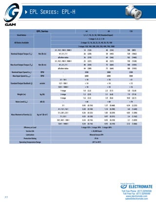
![20
SPL-K
60 75 100 140 180
mm (in) mm (in) mm (in) mm (in) mm (in)
D1 max standard motor shaft diameter 14 (0.551) 19 (0.748) 24 (0.945) 32 (1.260) 54 (2.126)
D1 max available* motor shaft diameter 19 (0.748) 24 (0.945) 32 (1.26) 38 (1.496) 54 (2.126)
D1 max 2-stage motor shaft diameter 14 (0.551) 19 (0.748) 24 (0.945) 34 (1.339) 38 (1.496)
D2max - KB max output bore 28 (1.102) 38 (1.496) 50 (1.969) 64 (2.520) 85 (3.346)
D2max - KE max output bore 26 (1.024) 38 (1.496) 46 (1.811) 56 (2.205) - -
D3g6- KB/E pilot diameter 70 (2.756) 85 (3.346) 115 (4.528) 135 (5.315) 180 (7.087)
D4 KB/E bolt circle 85 (3.346) 105 (4.134) 140 (5.512) 165 (6.496) 215 (8.465)
D5 KB/E bolt hole 6.6 (0.26) 9 (0.354) 11 (0.433) 13 (0.512) 17 (0.669)
L1 1-stage KB/E** gearbox total length 180 (7.087) 207 (8.150) 241.5 (9.508) 300 (11.811) 326 (12.835)
L1 2-stage KB/E** gearbox total length 207 (8.150) 233.5 (9.193) 266 (10.472) 350 (13.780) 340 (13.386)
L3 KB/E pilot height 6 (0.236) 8 (0.315) 10 (0.394) 12 (0.472) 15 (0.591)
L4 KB/E output flange size 70 (2.756) 95 (3.74) 120 (4.724) 145 (5.709) 190 (7.48)
L5** gearbox thickness 70 (2.756) 81 (3.189) 106 (4.173) 146 (5.748) 200 (7.874)
L6 KB/E flange thickness 7 (0.276) 9 (0.354) 11 (0.433) 13 (0.512) 15 (0.591)
t1min - KB min shaft engagement 21 (0.827) 26 (1.024) 32 (1.260) 33 (1.300) 59 (2.323)
t1max - KB max shaft engagement 43 (1.693) 58.5 (2.3031) 60 (2.362) 68 (2.677) 88 (3.465)
t1min - KE min shaft engagement 22 (0.866) 28 (1.102) 34 (1.339) 36 (1.417) - -
t1max - KE max shaft engagement 31.5 (1.240) 38.5 (1.516) 45 (1.772) 48.5 (1.909) - -
* for larger motor shaft diameters, please contact GAM ** depending on the motor, value can vary
TYPE CODES FOR SPL-K SERIES
Example: SPL - KE - 060 - 005 G - [115-201] - S111
Gearbox Series
SPL Series Special Options
Assigned by GAM
Motor Mount Kit
Assigned by GAM
Gearbox Style
KB = Bellows coupling output
KE = Elastomer coupling output
Gearbox Size
060, 075, 100, 140, 180
Ratio
3, 4, 5, 7, 10, 12, 16, 20, 25, 35, 40, 50, 70, 100
Options Available for This Product
G = Standard backlash and keyway in
output coupling
C = Reduced backlash and keyway in
output coupling
H = Standard backlash and no keyway
in output coupling
A = Reduced backlash and no keyway
in output coupling
Tolerances (mm)
Size k6 g6
Over 6 +0.010 -0.005
Thru 10 +0.001 -0.014
Over 10 +0.012 -0.006
Thru 18 +0.001 -0.017
Over 18 +0.015 -0.007
Thru 30 +0.002 -0.020
Over 30 +0.018 -0.009
Thru 50 +0.002 -0.025
Over 50 +0.021 -0.010
Thru 80 +0.002 -0.029
Over 80 +0.025 -0.012
Thru 120 +0.003 -0.034
Over 120 +0.028 -0.014
Thru 180 +0.003 -0.037
Sold & Serviced By:
ELECTROMATE
Toll Free Phone (877) SERVO98
Toll Free Fax (877) SERV099
www.electromate.com
sales@electromate.com](https://image.slidesharecdn.com/gamcatalog-141001201524-phpapp01/85/Gam-catalog-20-320.jpg)
![22
I.M.P.A.C.T.® Series - JPG-W
SPL-F
60 75 100 140 180
mm (in) mm (in) mm (in) mm (in) mm (in)
D1 max standard motor shaft diameter 14 (0.551) 19 (0.748) 24 (0.945) 32 (1.260) 54 (2.126)
D1 max available* motor shaft diameter 19 (0.748) 24 (0.945) 32 (1.26) 38 (1.496) 54 (2.126)
D1 max 2-stage motor shaft diameter 14 (0.551) 19 (0.748) 24 (0.945) 34 (1.339) 38 (1.496)
D2max - FB max output bore 28 (1.102) 38 (1.496) 50 (1.969) 64 (2.520) 85 (3.346)
D2max - FE max output bore 26 (1.024) 38 (1.496) 46 (1.811) 56 (2.205) - -
D3g6- FB/E pilot diameter 60 (2.362) 70 (2.756) 90 (3.543) 130 (5.118) 160 (6.299)
D4 FB/E bolt circle 68 (2.677) 85 (3.346) 120 (4.724) 165 (6.496) 215 (8.465)
D5 FB/E bolt hole ø5.5 ø6.6 ø9 ø11 ø13
L1 1-stage FB** gearbox total length 169 (6.653) 196.5 (7.736) 223 (8.779) 280 (11.024) 304 (11.968)
L1 2-stage FB** gearbox total length 196 (7.716) 223 (8.779) 247.5 (9.744) 330 (12.992) 327 (12.874)
L1 1-stage FE** gearbox total length 171 (6.732) 196.5 (7.736) 226.5 (8.917) 290 (11.417) - -
L1 2-stage FE** gearbox total length 198 (7.795) 223 (8.779) 251 (9.882) 340 (13.386) - -
L2 FB coupling length 76 (2.992) 83 (2.047) 105 (4.134) 117 (4.606) 112 (4.409)
L2 FE coupling length 79 (3.110) 94 (3.700) 104 (4.094) 125 (4.921) - -
L3 FB/E pilot height 20 (0.787) 20 (0.787) 30 (1.181) 30 (1.181) 14 (0.551)
L4 FB/E output flange size 65 (2.559) 76 (2.992) 101 (3.976) 141 (5.551) 180 (7.087)
L5** gearbox thickness 70 (2.756) 81 (3.189) 106 (4.173) 146 (5.748) 200 (7.874)
L6 FB/E flange thickness 6 (0.236) 7 (0.276) 10 (0.394) 12 (0.472) 20 (0.787)
t1min - FB min shaft engagement 21 (0.827) 26 (1.024) 32 (1.260) 33 (1.300) 59 (2.323)
t1max - FB max shaft engagement 39 (1.535) 43 (1.693) 58 (2.165) 52 (2.047) 88 (3.465)
t1min - FE min shaft engagement 22 (0.866) 28 (1.102) 34 (1.339) 36 (1.417) - -
t1max - FE max shaft engagement 31.5 (1.240) 38.5 (1.516) 45 (1.772) 48.5 (1.909) - -
* for larger motor shaft diameters, please contact GAM ** depending on the motor, value can very
TYPE CODES FOR SPL-F SERIES
Example: SPL - FE - 060 - 005 G - [115-201] - S111
Gearbox Series
SPL Series.
Special Options
Assigned by GAM
Motor Mount Kit
Assigned by GAM
Gearbox Style
FB = Bellows coupling output
FE = Elastomer coupling output
Gearbox Size
060, 075, 100, 140, 180
Ratio
3, 4, 5, 7, 10, 12, 16, 20, 25, 35, 40, 50, 70, 100
Options Available for This Product
G = Standard backlash and keyway in
output coupling
C = Reduced backlash and keyway in
output coupling
H = Standard backlash and no keyway
in output coupling
A = Reduced backlash and no keyway
in output coupling
Tolerances (mm)
Size k6 g6
Over 6 +0.010 -0.005
Thru 10 +0.001 -0.014
Over 10 +0.012 -0.006
Thru 18 +0.001 -0.017
Over 18 +0.015 -0.007
Thru 30 +0.002 -0.020
Over 30 +0.018 -0.009
Thru 50 +0.002 -0.025
Over 50 +0.021 -0.010
Thru 80 +0.002 -0.029
Over 80 +0.025 -0.012
Thru 120 +0.003 -0.034
Over 120 +0.028 -0.014
Thru 180 +0.003 -0.037
Sold & Serviced By:
ELECTROMATE
Toll Free Phone (877) SERVO98
Toll Free Fax (877) SERV099
www.electromate.com
sales@electromate.com](https://image.slidesharecdn.com/gamcatalog-141001201524-phpapp01/85/Gam-catalog-22-320.jpg)


![26
L1
D1
L2 L6
D4
L7
L8
D3h7
D5
L5
L3
L4
D2k6
f1
f2
EPL-W
EPL-W Series
50 64 84 118 150
mm (in) mm (in) mm (in) mm (in) mm (in)
D1 max standard* motor shaft diameter 11 (0.433) 14 (0.551) 19 (0.748) 24 (0.945) 28 (1.102)
D1 max available* motor shaft diameter 14 (0.551) 16 (0.63) 24 (0.945) 32 (1.26) 38 (1.496)
D2 k6 output shaft diameter 12 (0.472) 14 (0.551) 20 (0.787) 25 (0.984) 40 (1.575)
D3 h7 pilot diameter 35 (1.378) 40 (1.575) 55 (2.165) 80 (3.15) 110 (4.331)
D4 bolt circle 44 (1.732) 52 (2.047) 70 (2.756) 100 (3.937) 130 (5.118)
D5 housing diameter 50 (1.969) 64 (2.52) 84 (3.307) 118 (4.646) 150 (5.906)
f1 shaft thread M4x8 M5x12 M6x16 M10x22 M10 x 22
f2 mounting holes M4x6 M5x12 M6x14 M8x18 M10x20
L1 1-STAGE**
gearbox total length
93 (3.661) 117 (4.606) 162 (6.378) 199 (7.835) 265 (10.433)
L1 2-STAGE** 109 (4.291) 139 (5.472) 195 (7.677) 239 (9.409) 305 (12.008)
L1 3-STAGE** - 161 (6.339) 228 (8.976) 280 (11.024) 346 (13.622)
L2 shaft length 24.5 (0.965) 39 (1.535) 54 (2.126) 61 (2.402) 81 (3.189)
L3 key length 16 (0.63) 25 (0.984) 36 (1.417) 45 (1.772) 60 (2.362)
L4 usable shaft length 18 (0.709) 30 (1.181) 45 (1.772) 50 (1.969) 70 (2.756)
L5 pilot height 4 (0.157) 8 (0.315) 8 (0.315) 10 (0.394) 10 (0.394)
L6 key width 4 (0.157) 5 (0.197) 6 (0.236) 8 (0.315) 12 (0.472)
L7 key height 13.5 (0.531) 16 (0.63) 22.5 (0.886) 28 (1.102) 43 (1.693)
L8** adapter size 50 (1.969) 70 (2.756) 90 (3.543) 120 (4.724) 150 (5.906)
* for larger motor shaft diameters, please contact GAM ** depending on the motor, value can vary
Recommended Output Coupling (if necessary)
metal bellows KLC-25 KLC-50 KLC-125 KM-270 KM-400
elastomer EKM-45 EKM-60 EKM-150 EKM-300 EKM-400
Tolerances (mm)
Size k6 h7
Over 10 +0.012 0
Thru 18 +0.001 -0.018
Over 18 +0.015 0
Thru 30 +0.002 -0.021
Over 30 +0.018 0
Thru 50 +0.002 -0.025
Over 50 +0.021 0
Thru 80 +0.002 -0.030
Over 80 +0.025 0
Thru 120 +0.003 -0.035
TYPE CODES FOR EPL SERIES (EPL-W)
Example: EPL - W - 084 - 005 G - [115 - A01] - S111
Gearbox Series
EPL w/ Metric Output
Special Options
Assigned by GAM
Motor Mount Kit
Assigned by GAM
Gearbox Style
W = Output Shaft
Gearbox Size
050, 064, 084, 118, 150
Ratio
3, 4, 5, 7, 10, 12, 16, 20, 25, 35, 40, 50, 70, 100,
120, 160, 200, 250, 350, 490, 700, 000=1000
Options Available for This Product
G = Key on output shaft per DIN6885
Sold & Serviced By:
ELECTROMATE
Toll Free Phone (877) SERVO98
Toll Free Fax (877) SERV099
www.electromate.com
sales@electromate.com](https://image.slidesharecdn.com/gamcatalog-141001201524-phpapp01/85/Gam-catalog-26-320.jpg)
![28
L1
D1
L8
L6
ØD4
EPL-X
D2 k6
D3 h7
L3
L4
L5 L2
L7
D5
NEMA-X Series
17 23 34 42 56
mm (in) mm (in) mm (in) mm (in) mm (in)
D1 max standard* motor shaft diameter 11 (0.433) 14 (0.551) 19 (0.748) 24 (0.945) 24 (0.945)
D1 max available* motor shaft diameter - (-) 16 (0.63) 24 (0.945) 32 (1.26) 32 (1.26)
D2 k6 output shaft diameter 9.525 (0.375) 12.7 (0.5) 19.050 (0.75) 25 (0.984) 25 (0.984)
D3 h7 pilot diameter 21.97 (0.865) 38.1 (1.5) 73 (2.874) 55.55 (2.187) 114.300 (4.50)
D4 bolt circle 43.8 (1.724) 66.7 (2.626) 98.400 (3.874) 125.7 (4.949) 177.800 (7.000)
D5 mounting holes 3.25 (0.128) 5 (0.197) 5.5 (0.217) 7.1 (0.28) 10.200 (0.402)
L1 1-STAGE**
gearbox total length
108 (4.252) 111 (4.37) 147 (5.787) 199 (7.835) 199 (7.835)
L1 2-STAGE** 124 (4.882) 133 (5.236) 180 (7.087) 239 (9.409) 239 (9.409)
L1 3-STAGE** 139.5 (5.492) 155 (6.102) 213 (8.386) 280 (11.024) 280 (11.024)
L2 shaft length 25.4 (1.000) 25.4 (1.000) 31.8 (1.252) 42 (1.654) 41 (1.614)
L3 key length - (-) 19.05 (0.75) 25.4 (1) 38 (1.496) 32 (1.26)
L4 pilot height 1.6 (0.063) 1.6 (0.063) 1.7 (0.067) 2.4 (0.094) 4 (0.157)
L5 flange thickness 4.9 (0.193) 5 (0.197) 10 (0.394) 19 (0.748) 20 (0.7874)
L6 key width - (-) 3.175 (0.125) 4.78 (0.188) 8 (0.315) 8 (0.315)
L7 key height / flat height 9.14 (0.36) 14.22 (0.56) 21.290 (0.838) 28 (1.102) 28 (1.102)
L8 flange size 40 (1.575) 65 (2.559) 90 (3.543) 120 (4.724) 145 (5.709)
* for larger motor shaft diameters, please contact GAM **depending on the motor, value can vary *** long motor shafts can be accommodated, but overall gearbox length will grow
Recommended Output Coupling (if necessary)
metal bellows KLC-25 KLC-50 KLC-125 KM-270 KM-400
elastomer EKM-20 EKM-60 EKM-150 EKM-300 EKM-400
TYPE CODES FOR EPL SERIES (EPL-X (NEMA))
Example: EPL - X23 - 005 G - [115 - A01] - S111
Gearbox Series
EPL w/ NEMA output
Special Options
Assigned by GAM
Motor Mount Kit
Assigned by GAM
Gearbox Style
X17 = NEMA17
X23 = NEMA23
X34 = NEMA34
X42 = NEMA42
X56 = NEMA56
Ratio
3, 4, 5, 7, 10, 12, 16, 20, 25, 35, 40, 50, 70, 100,
120, 160, 200, 250, 350, 490, 700, 000=1000
Options Available for This Product
G = Key on output shaft per DIN6885
Tolerances (mm)
Size k6 h7
Over 10 +0.012 0
Thru 18 +0.001 -0.018
Over 18 +0.015 0
Thru 30 +0.002 -0.021
Over 30 +0.018 0
Thru 50 +0.002 -0.025
Over 50 +0.021 0
Thru 80 +0.002 -0.030
Over 80 +0.025 0
Thru 120 +0.003 -0.035
Sold & Serviced By:
ELECTROMATE
Toll Free Phone (877) SERVO98
Toll Free Fax (877) SERV099
www.electromate.com
sales@electromate.com](https://image.slidesharecdn.com/gamcatalog-141001201524-phpapp01/85/Gam-catalog-28-320.jpg)
![30
L1
D1
EPL-A
D3h6
D4
L3 L6
L2
D5
L8
L7
L4
D2k6
L5 f1
f2
Recommended Output Coupling (if necessary)
metal bellows KLC-25 KLC-50 KLC-125 KM-270 KM-400
elastomer EKM-20 EKM-60 EKM-150 EKM-300 EKM-400
TYPE CODES FOR EPL SERIES (EPL-A)
Example: EPL - A - 090 - 005 G - [115 - A01] - S111
Gearbox Series
EPL w/ Popular Metric
Output Dimensions
Special Options
Assigned by GAM
Motor Mount Kit
Gearbox Style Assigned by GAM
A= Output Shaft
Ratio
3, 4, 5, 7, 10, 12, 16, 20, 25, 35, 40, 50, 70, 100,
120, 160, 200, 250, 350, 490, 700, 000=1000
Options Available for This Product
G = Key on output shaft per DIN6885
Tolerances (mm)
Size k6 h6
Over 10 +0.012 0
Thru 18 +0.001 -0.011
Over 18 +0.015 0
Thru 30 +0.002 -0.013
Over 30 +0.018 0
Thru 50 +0.002 -0.016
Over 50 +0.021 0
Thru 80 +0.002 -0.019
Over 80 +0.025 0
Thru 120 +0.003 -0.022
EPL-A Series
50 70 90 120 155
mm (in) mm (in) mm (in) mm (in) mm (in)
D1 max standard* motor shaft diameter 11 (0.433) 14 (0.551) 19 (0.748) 24 (0.945) 28 (1.102)
D1 max available* motor shaft diameter 14 (0.551) 16 (0.630) 24 (0.945) 32 (1.260) 38 (1.496)
D2 k6 output shaft diameter 12 (0.472) 16 (0.630) 22 (0.866) 32 (1.260) 40 (1.575)
D3h6 pilot diameter 35 (1.378) 52 (2.047) 68 (2.677) 90 (3.543) 120 (4.724)
D4 Bolt Circle 44 (1.732) 62 (2.441) 80 (3.150) 108 (4.252) 140 (5.512)
D5 Housing Diameter 50 (1.968) 70 (2.756) 90 (3.543) 118 (4.646) 155 (6.102)
f1 Shaft Thread M4x8 M5x17 M8x25 M12x37 M16x45
f2 Mounting Holes (8x) M4x6 (8x) M5x12 (8x) M6x14 (8x) M8x18 (8x) M10x24
L1 1-STAGE**
gearbox total length
93 (3.661) 130 (5.118) 164 (6.457) 222 (8.740) 300 (11.811)
L1 2-STAGE** 109 (4.291) 152 (5.984) 196 (7.717) 263 (10.354) 341 (13.425)
L1 3-STAGE** - - 174 (6.850) 229 (9.016) 304 (11.968) 382 (15.039)
L2 Shaft length 24.5 (0.965) 36 (1.417) 46 (1.811) 70 (2.756) 94 (3.701)
L3 Key Length 16 (0.630) 25 (0.984) 30 (1.181) 50 (1.968) 70 (2.756)
L4 Useable Shaft Length 18 (0.709) 28 (1.102) 35 (1.378) 58 (2.283) 82 (3.228)
L5 Pilot Height 4 (0.157) 5.5 (0.217) 9 (0.354) 7 (0.276) 5.5 (0.217)
L6 Key Width 4 (0.157) 5 (0.197) 6 (0.236) 10 (0.394) 12 (0.472)
L7 Key Height 13.5 (0.531) 18 (0.709) 24.5 (0.965) 35 (1.378) 43 (1.693)
L8** Adapter Size 50 (1.968) 70 (2.756) 90 (3.543) 120 (4.724) 150 (5.905)
* for larger motor shaft diameters, please contact GAM **depending on the motor, value can vary *** longer motor shafts can be accommodated, but overall gearbox length will grow
Gearbox Size
050, 070, 090, 120, 155
Sold & Serviced By:
ELECTROMATE
Toll Free Phone (877) SERVO98
Toll Free Fax (877) SERV099
www.electromate.com
sales@electromate.com](https://image.slidesharecdn.com/gamcatalog-141001201524-phpapp01/85/Gam-catalog-30-320.jpg)

![32
f1
L5
L1
D1
D11 H7
D9 (8x)
D8
D7
D4 h7
D2 h7
D5
L4
L3
EPL-F
L6
D10 H7
L2
TYPE CODES FOR EPL SERIES (EPL-F)
EPL-F Series
Example: EPL - F - 090 - 005 H - [115 - A01] - S111
Gearbox Series
EPL w/ Flange Output
Special Options
Assigned by GAM
Motor Mount Kit
Assigned by GAM
Gearbox Style
F = Flange Output Shaft
Ratio
3, 4, 5, 7, 10, 12, 16, 20, 25, 35, 40, 50, 70, 100,
120, 160, 200, 250, 350, 490, 700, 000=1000
Options Available for This Product
H= No Keyways
Tolerances (mm)
Size h7 H7
Over 10 0 0.018
Thru 18 -0.018 0
Over 18 0 0.021
Thru 30 -0.021 0
Over 30 0 +0.025
Thru 50 -0.025 0
Over 50 0 +0.030
Thru 80 -0.030 0
Over 80 0 +0.035
Thru 120 -0.035 0
Gearbox Size
064, 090, 110
64 90 110
mm (in) mm (in) mm (in)
D1 max standard* motor shaft diameter 14 (0.551) 19 (0.748) 24 (0.945)
D1 max available* motor shaft diameter 16 (0.630) 24 (0.945) 32 (1.260)
D2 h7 output flange diameter 40 (1.575) 63 (2.480) 80 (3.150)
D4 h7 pilot diameter 64 (2.520) 90 (3.543) 110 (4.331)
D5 flange diameter 86 (3.386) 118 (4.646) 145 (5.709)
D7 inner bolt circle 31.5 (1.240) 50 (1.968) 63 (2.480)
D8 outer bolt circle 79 (3.110) 109 (4.291) 135 (5.315)
D9 mounting hole diameter (8x) 4.5 (0.177) 5.5 (0.217) 5.5 (0.217)
D10 H7 flange pilot 20 (0.787) 31.5 (1.240) 40 (1.575)
D11 H7 dowel diameter 5 (0.197) 6 (0.236) 6 (0.236)
f1 flange tap (7) M5x7 (7) M6x10 (7) M6x12
L1 1-STAGE**
gearbox total length
93 (3.661) 126 (4.961) 150 (5.905)
L1 2-STAGE** 113 (4.490) 158 (6.220) 190 (7.480)
L1 3-STAGE** 129 (5.08) 191 (7.520) 231 (9.094)
L2 flange pilot depth 4 (0.157) 6 (0.236) 6 (0.236)
L3 pilot height 7 (0.276) 10 (0.394) 10 (0.394)
L4 output length 19.5 (0.768) 30 (1.181) 29 (1.142)
L5 flange thickness 4 (0.157) 7 (0.276) 8 (0.315)
L6 output flange length 3 (0.118) 6 (0.236) 6 (0.236)
* for larger motor shaft diameters, please contact GAM ** depending on the motor, value can vary
Sold & Serviced By:
ELECTROMATE
Toll Free Phone (877) SERVO98
Toll Free Fax (877) SERV099
www.electromate.com
sales@electromate.com](https://image.slidesharecdn.com/gamcatalog-141001201524-phpapp01/85/Gam-catalog-32-320.jpg)
![34
EPL Series
64 84 118
mm (in) mm (in) mm (in)
D1 max standard* motor shaft diameter 14 (0.551) 19 (0.748) 24 (0.945)
D1 max available* motor shaft diameter 16 (0.63) 24 (0.945) 32 (1.26)
D2 max output shaft diameter 16 (0.63) 20 (0.787) 30 (1.181)
D3 H7 pilot diameter 44 (1.732) 60 (2.362) 80 (3.15)
D4 bolt circle 55.5 (2.185) 73 (2.874) 105 (4.134)
D5 flange diameter 70 (2.756) 84 (3.307) 118 (4.646)
D6 mounting holes 5.5 (0.217) 5.5 (0.217) 6.6 (0.26)
L1 1-STAGE**
gearbox total length
98.5 (3.878) 122 (4.803) 155.5 (6.122)
L1 2-STAGE** 120.5 (4.744) 155 (6.102) 196 (7.717)
L1 3-STAGE** 142.5 (5.61) 188 (7.402) 236.5 (9.311)
L2 pilot depth 3.5 (0.138) 3.5 (0.138) 3.5 (0.138)
L3 flange size 70 (2.756) 90 (3.543) 120 (4.724)
L4 allowable shaft depth 28 (1.102) 30 (1.181) 27 (1.063)
L5 flange thickness 6 (0.236) 6 (0.236) 10 (0.394)
W1 bolt hole spacing 125° 4x 90° 4x 90°
W2 hole angle 1 27.5° 67.5° 67.5°
W3 hole angle 2 27.5° 22.5° 22.5°
* for larger motor shaft diameters, please contact GAM ** depending on the motor, value can vary
Tolerances (mm)
Size H7
Over 6 +0.015
Thru 10 0
Over 10 +0.018
Thru 18 0
Over 18 +0.021
Thru 30 0
Over 30 +0.025
Thru 50 0
Over 50 +0.030
Thru 80 0
TYPE CODES FOR EPL SERIES (EPL-H)
Example: EPL - H - 084 - 005 H - [115 - A01] - S111
Gearbox Series
EPL w/ Linear Mount
Output
Special Options
Assigned by GAM
Motor Mount Kit
Gearbox Style Assigned by GAM
H = Hollow Output Shaft
Gearbox Size
064, 084, 118
Ratio
3, 4, 5, 7, 10, 12, 16, 20, 25, 35, 40, 50, 70, 100,
120, 160, 200, 250, 350, 490, 700, 000 = 1000
Options Available for This Product
H = No Keyways
Sold & Serviced By:
ELECTROMATE
Toll Free Phone (877) SERVO98
Toll Free Fax (877) SERV099
www.electromate.com
sales@electromate.com](https://image.slidesharecdn.com/gamcatalog-141001201524-phpapp01/85/Gam-catalog-34-320.jpg)

![38
D4
L6
L2
L3
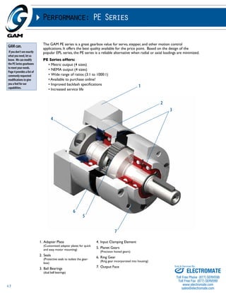
SSP-W
D5
D3h7
L7
L8
f1
L4
L5
D2k6
f2
L1
D1
SSP Series
70 90 120
mm (in) mm (in) mm (in)
D1 max standard motor shaft diameter 14 (0.551) 19 (0.748) 24 (0.945)
D1 max available* motor shaft diameter 16 (0.63) 24 (0.945) 32 (1.26)
D2 k6 output shaft diameter 16 (0.63) 22 (0.866) 32 (1.26)
D3 h7 pilot diameter 52 (2.047) 68 (2.677) 90 (3.543)
D4 bolt circle 62 (2.441) 80 (3.15) 108 (4.252)
D5 housing diameter 70 (2.756) 92 (3.622) 122 (4.803)
f1 shaft thread M5x12 M6x16 M10x22
f2 mounting holes M6x12 M6x14 M8x18
L1 1-STAGE***
gearbox total length
131 (5.157) 174 (6.85) 232 (9.134)
L1 2-STAGE*** 153 (6.024) 207 (8.15) 271 (10.669)
L2 shaft length 36 (1.417) 46 (1.811) 70 (2.756)
L3 key length 25 (0.984) 30 (1.181) 50 (1.969)
L4 usable shaft length 28 (1.102) 36 (1.417) 58 (2.283)
L5 pilot height 7 (0.276) 9 (0.354) 11 (0.433)
L6 key width 5 (0.197) 6 (0.236) 8 (0.315)
L7 key height 18 (0.709) 24.600 (0.969) 34.8 (1.37)
* for these larger motor shaft diameters, please contact GAM
** depending on the motor, value can vary
Recommended Output Coupling (if necessary)
all stainless bellows KG-VA-80 KG-VA-220 KG-VA-350
TYPE CODES FOR SSP SERIES (SSP-W)
Example: SSP - W - 090 - 005 G - [115 - A01] - S111
Gearbox Series
Stainless Steel
Planetary Series
Special Options
Assigned by GAM
Motor Mount Kit
Gearbox Style Assigned by GAM
W = Output Shaft
Gearbox Size
070, 090, 120
Ratio
3, 4, 5, 7, 10, 12, 16, 20, 25, 35, 40, 50, 70, 100
Options Available for This Product
G = Key on output DIN688
Tolerances (mm)
Size k6 h7
Over 10 +0.012 0
Thru 18 +0.001 -0.018
Over 18 +0.015 0
Thru 30 +0.002 -0.021
Over 30 +0.018 0
Thru 50 +0.002 -0.025
Over 50 +0.021 0
Thru 80 +0.002 -0.030
Over 80 +0.025 0
Thru 120 +0.003 -0.035
Sold & Serviced By:
ELECTROMATE
Toll Free Phone (877) SERVO98
Toll Free Fax (877) SERV099
www.electromate.com
sales@electromate.com](https://image.slidesharecdn.com/gamcatalog-141001201524-phpapp01/85/Gam-catalog-38-320.jpg)


![42
FP Series
50 70 90 120
mm (in) mm (in) mm (in) mm (in)
D1max motor shaft diameter 14 (0.551) 14 (0.551) 22 (0.866) 28 (1.102)
D1max (2-Stage) motor shaft diameter 14 (0.551) 14 (0.551) 19 (0.748) 22 (0.866)
D2 output flange diameter 42 (1.654) 55 (2.165) 75 (2.953) 105 (4.134)
D4 h7 pilot diameter 57 (2.244) 72 (2.835) 100 (3.937) 130 (5.118)
D5 flange diameter 69 (2.717) 84 (3.307) 118 (4.646) 150 (5.906)
D6 input housing diameter 56 (2.205) 72 (2.835) 100 (3.937) 130 (5.118)
D7 inner bolt circle 28 (1.102) 36 (1.417) 60 (2.362) 80 (3.150)
D8 outer bolt circle 63 (2.480) 78 (3.071) 109 (4.291) 140 (5.512)
D9 mounting holes 3.5 (0.138) 3.5 (0.138) 4.5 (0.177) 5.5 (0.217)
D10 H7 flange pilot 12 (0.472) 19 (0.748) 28 (1.102) 40 (1.575)
D11 dowel diameter x depth 4 x 4 5x5 6x6 8x8
f1 flange through holes 6 x M4 6 x M5 6 x M6 6 x M8
f2 threaded mounting holes M3 M3 M4 M5
L1** (1-Stage) gearbox total length 69 (2.717) 83 (3.268) 107 (4.213) 134 (5.276)
L1** (2-Stage) gearbox total length 100 (3.937) 95 (3.740) 120 (4.724) 147 (5.787)
L2 flange pilot depth 5 (0.197) 5 (0.197) 8 (0.315) 7 (0.276)
L3 pilot height 12 (0.472) 12 (0.472) 17 (0.669) 21 (0.827)
L4 output length 29 (1.142) 33 (1.299) 40.5 (1.594) 52.5 (2.067)
L5 flange length 15.5 (0.610) 20 (0.787) 28 (1.102) 37 (1.457)
L6 output flange height 3 (0.118) 3 (0.118) 3.5 (0.138) 3.5 (0.138)
L7 radial load distance 24.75 (0.974) 29.5 (1.161) 37 (1.457) 45.25 (1.781)
* for larger motor shaft diameters, please contact GAM ** depending on the motor, value can vary
TYPE CODES FOR FP SERIES (FP)
Example: FP - F - 070 - 005H - [115 - A01] - S111
Gearbox Series
FP = Flange Planetary
Special Options
Assigned by GAM
Motor Mount Kit
Assigned by GAM
Gearbox Style
F = Output Flange Rotates
P = Gearbox Housing Rotates
FB = Bellows Coupling Output
Gearbox Size
050, 070, 090, 120
Ratio
4, 5, 7, 10, 16, 20, 21, 25, 28, 31, 35, 43, 49, 61, 91
(91:1 not available for size 50)
Ratio for FP-P is (n-1)
Options Available for This Product
H = standard backlash
A = reduced backlash
Tolerances (mm)
Size h7 H7
Over 10 0 +0.018
Thru 18 -0.018 0
Over 18 0 +0.021
Thru 30 -0.021 0
Over 30 0 +0.025
Thru 50 -0.025 0
Over 50 0 +0.030
Thru 80 -0.030 0
Over 80 0 +0.035
Thru 120 -0.035 0
Over 120 0 +0.040
Thru 180 -0.040 0
FP
Sold & Serviced By:
ELECTROMATE
Toll Free Phone (877) SERVO98
Toll Free Fax (877) SERV099
www.electromate.com
sales@electromate.com](https://image.slidesharecdn.com/gamcatalog-141001201524-phpapp01/85/Gam-catalog-42-320.jpg)


![46
t1
L7
L8
D4
L5
L4
PE-W
D5
D3h7
f1
L2
L3
D2k6
f2 L6
L1
D1
mm (in) 50 64 84 118
D1 max standard* motor shaft diameter 11 (0.433) 14 (0.551) 19 (0.748) 24 (0.945)
D1 max available* motor shaft diameter 14 (0.551) 16 (0.630) 24 (0.945) 32 (1.260)
D2 k6 output shaft diameter 12 (0.472) 14 (0.551) 20 (0.787) 25 (0.984)
D3 h7 pilot diameter 35 (1.378) 40 (1.575) 55 (2.165) 80 (3.15)
D4 bolt circle 44 (1.732) 52 (2.047) 70 (2.756) 100 (3.937)
D5 housing diameter 50 (1.969) 64 (2.52) 84 (3.307) 118 (4.646)
f1 shaft thread M4x8 M5x12 M6x16 M10x22
f2 mounting holes M4x6 M5x12 M6x14 M8x18
L1 1-STAGE**
gearbox total length
93 (3.661) 117 (4.606) 162 (6.378) 199 (7.835)
L1 2-STAGE** 108 (4.252) 139 (5.472) 195 (7.677) 239 (9.409)
L1 3-STAGE** - (-) 161 (6.339) 228 (8.976) 280 (11.024)
L2 shaft length 24.5 (0.965) 39 (1.535) 54 (2.126) 61 (2.402)
L3 key length 16 (0.63) 25 (0.984) 36 (1.417) 45 (1.772)
L4 usable shaft length 18 (0.709) 30 (1.181) 45 (1.772) 50 (1.969)
L5 pilot height 4 (0.157) 8 (0.315) 8 (0.315) 10 (0.394)
L6 key width 4 (0.157) 5 (0.197) 6 (0.236) 8 (0.315)
L7 key height 13.5 (0.531) 16 (0.63) 22.5 (0.886) 28 (1.102)
L8** adapter size 50 (1.969) 70 (2.756) 90 (3.543) 120 (4.724)
t1*** allowable shaft length 23 (0.87) 23 (0.906) 30 (1.181) 40 (1.575)
* for larger motor shaft diameters, please contact GAM ** depending on the motor, value can vary *** long motor shafts can be accommodated, but overall gearbox length will grow
****The PE-W-050 may have a blue ring gear
Recommended Output Coupling (if necessary)
metal bellows KLC-25 KLC-50 KLC-125 KM-270
elastomer EKC-25 EKC-35 EKC-80 or 110 EKM-300
Tolerances (mm)
Size k6 h7
Over 6 +0.010 0
Thru 10 +0.001 -0.015
Over 10 +0.012 0
Thru 18 +0.001 -0.018
Over 18 +0.015 0
Thru 30 +0.002 -0.021
Over 30 +0.018 0
Thru 50 +0.002 -0.025
Over 50 +0.021 0
Thru 80 +0.002 -0.030
TYPE CODES FOR PE-W SERIES (METRIC)
Example: PE - W - 084 - 005 G - [115 - A01] - S111
Gearbox Series
PE w/ Metric Output
Special Options
Assigned by GAM
Motor Mount Kit
Assigned by GAM
Gearbox Style
W = Output Shaft
Gearbox Size
050, 064, 084, 118
Ratio
3, 4, 5, 7, 10, 12, 16, 20, 25, 35, 40, 50, 70, 100,
120, 160, 200, 250, 350, 490, 700, 000=1000
Options Available for This Product
G = Key on output shaft per DIN6885
Sold & Serviced By:
ELECTROMATE
Toll Free Phone (877) SERVO98
Toll Free Fax (877) SERV099
www.electromate.com
sales@electromate.com](https://image.slidesharecdn.com/gamcatalog-141001201524-phpapp01/85/Gam-catalog-46-320.jpg)

![48
t1
L6
ØD4
PE-N
L3
D3 h7
D2 k6
L7
D5
L2
L4
D1
L5
L1 L8
PE-N Series
17 23 34 42
mm (in) mm (in) mm (in) mm (in)
D1 max standard* motor shaft diameter 11 (0.433) 11 (0.433) 14 (0.551) 19 (0.748)
D1 max available* motor shaft diameter 11 (0.433) 14 (0.551) 16 (0.630) 24 (0.945)
D2 k6 output shaft diameter 9.525 (0.375) 9.525 (0.375) 12.700 (0.500) 19.05 (0.750)
D3 h7 pilot diameter 21.97 (0.865) 38.100 (1.500) 73.025 (2.875) 55.55 (2.187)
D4 bolt circle 43.8 (1.725) 66.7 (2.625) 98.400 (3.875) 125.7 (4.95)
D5 mounting holes 3.25 (0.128) 5 (0.2) 5.5 (0.22) 7.1 (0.28)
L1 1-STAGE**
gearbox total length
108 (4.252) 102 (4.016) 125 (4.921) 162 (6.378)
L1 2-STAGE** 124 (4.882) 122.5 (4.823) 147 (5.787) 194.5 (7.657)
L1 3-STAGE** - (-) - (-) 169 (6.654) 227 (8.937)
L2 shaft length 25.4 (1.00) 25.4 (1.00) 31.8 (1.25) 31.8 (1.25)
L3 key length - (-) - (-) 27 (1.06) 29 (1.14)
L4 pilot height 1.6 (0.063) 1.6 (0.06) 1.7 (0.07) 2.4 (0.09)
L5 flange thickness 4.9 (0.193) 5 (0.2) 10 (0.39) 13 (0.51)
L6 key width - (-) - (-) 3.2 (0.13) 4.8 (0.19)
L7 key height / flat height 9.14 (0.36) 9.14 (0.36) 14.3 (0.56) 18.260 (0.72)
L8 output flange size 40 (1.575) 57.14 (2.25) 82.55 (3.25) 106.68 (4.20)
t1*** allowable motor shaft 25 (0.984) 23 (0.87) 32 (1.26) 40 (1.575)
* for larger motor shaft diameters, please contact GAM **depending on the motor, value can vary *** longer motor shafts can be accommodated, but overall gearbox length will grow
Recommended Output Coupling (if necessary)
metal bellows KLC-25 KLC-25 KLC-50 KLC-125
elastomer EKC-25 EKC-25 EKC-80 EKC-110
Tolerances (mm)
Size k6 h7
Over 6 +0.010 0
Thru 10 +0.001 -0.015
Over 10 +0.012 0
Thru 18 +0.001 -0.018
Over 18 +0.015 0
Thru 30 +0.002 -0.021
Over 30 +0.018 0
Thru 50 +0.002 -0.025
Over 50 +0.021 0
Thru 80 +0.002 -0.030
TYPE CODES FOR PE-N SERIES (NEMA)
Example: PE - N23 - 005 G - [115 - A01] - S111
Gearbox Series
NPE w/ NEMA output
Special Options
Assigned by GAM
Motor Mount Kit
Assigned by GAM
Gearbox Style
N17 = NEMA17
N23 = NEMA23
N34 = NEMA34
N42 = NEMA42
Ratio
3, 4, 5, 7, 10, 12, 16, 20, 25, 35, 40, 50, 70, 100,
120, 160, 200, 250, 350, 490, 700, 000=1000
Options Available for This Product
G = Key on output shaft per DIN6885
flat on NEMA 17 and NEMA 23
Sold & Serviced By:
ELECTROMATE
Toll Free Phone (877) SERVO98
Toll Free Fax (877) SERV099
www.electromate.com
sales@electromate.com](https://image.slidesharecdn.com/gamcatalog-141001201524-phpapp01/85/Gam-catalog-48-320.jpg)


![W1
L13
L2
L9
L9
Example: DS - W B - 090 - 005 G - [115-201] - S111
Gearbox Series
DS = Dyna Series
DSX = Dyna Series Extreme
Sold & Serviced By:
53
Dyna Series - DS-W, DS-H, DS-T, DS-F
f1
Recommended Output Coupling (if necessary)
D3 g6
L5 L1 L5
metal bellows KM-60 KM-170 KM-270 KM-400 KM-1300 KSD-2500
elastomer EKM-60 EKM-150 EKM-300 EKM-500 EKM-1000 -
Tolerances (mm)
Size k6 g6 h8 f7 H7 h6
Over 6 +0.010 -0.005 0 -0.013 +0.015 0
Thru 10 +0.001 -0.014 -0.022 -0.028 0 -0.009
Over 10 +0.012 -0.006 0 -0.016 +0.018 0
Thru 18 +0.001 -0.017 -0.027 -0.034 0 -0.011
Over 18 +0.015 -0.007 0 -0.02 +0.021 0
Thru 30 +0.002 -0.020 -0.033 -0.041 0 -0.013
Over 30 +0.018 -0.009 0 -0.025 +0.025 0
Thru 50 +0.002 -0.025 -0.039 -0.05 0 -0.016
Over 50 +0.021 -0.010 0 -0.03 +0.030 0
Thru 80 +0.002 -0.029 -0.046 -0.06 0 -0.019
Over 80 +0.025 -0.012 0 -0.036 +0.035 0
Thru 120 +0.003 -0.034 -0.054 -0.021 0 -0.022
Over 120 +0.028 -0.014 0 -0.043 +0.040 0
Thru 180 +0.003 -0.039 -0.063 -0.083 0 -0.025
Special Options
Assigned by GAM
Motor Mount Kit
Assigned by GAM
LOW OUTPUT
TYPE CODES FOR DYNA SERIES
OPTION BACKLASH KEYWAY
A= Y N
C= Y Y
G= N Y
H= N N
Gearbox Style
W = Single output shaft
T = Dual output shaft
H = Hollow output shaft
F = Flange output
Input Type
B = Bellows coupling input
E = Elastomer coupling input
L = Shaft input
Gearbox Size
055, 075, 090, 115, 130, 140, 160, 190
Options Available for This Product
Ratio
003, 004, 005, 006, 008, 010,
012, 015, 030, 040, 050, 070, 100
Options C and G N/A for DS-F/H models.
Contact GAM for DSX Drawings
DS-F
L20
D12 H7
D11 h8
L21
L19
f2
W2
D7 H7
D8
L13
L2
L15
L2
DS-H
L12
D4 H7
L4
L7
D5 f7
D4 H7
L6
L13 L13
L18
L14
L11
D1
L13 L5 L1
L10
D3 g6
L5
L14
L2
L13
D8
L13 L13
L10
D2 k6
D2 k6
DS-T
L16
L3
L8
L3
L8
f3
DS-W
D2 k6
D9 k6
L17 f1
L15
L3
f3
L9
L8
L12
L12
L11
D1
ELECTROMATE
Toll Free Phone (877) SERVO98
Toll Free Fax (877) SERV099
www.electromate.com
sales@electromate.com](https://image.slidesharecdn.com/gamcatalog-141001201524-phpapp01/85/Gam-catalog-53-320.jpg)


![58
Ø D4
L10
Ø D6 H7
Ø D7
f2
Ø D1
L1
L8
L4
L9
L5 L3
L6
Ø D5
L7
L2
Ø D2 k6
Ø D3 g6
Ø D6 H7
DL-DW DL-DH
DL - DW and DL - DH
55 75 90
mm (in) mm (in) mm (in)
D1 max (1 stage)* motor shaft diameter 16 (0.63) 20 (0.787) 35 (1.378)
D1 max (2 stage standard)* motor shaft diameter 14 (0.551) 19 (0.748) 19 (0.748)
D1 max (2 stage available)* motor shaft diameter 16 (0.63) 24 (0.945) 24 (0.945)
D2 k6 output shaft diameter 20 (0.787) 24 (0.945) 32 (1.26)
D3 g6 pilot diameter 89 (3.504) 105 (4.134) 125 (4.921)
D4 bolt circle 110.3 (4.343) 138.6 (5.457) 166.8 (6.567)
D5 mounting holes 6.6 (0.26) 9 (0.354) 11 (0.433)
D6 H7** hollow bore diameter 20 (0.787) 25 (0.984) 30 (1.181)
D7 shrink disc OD (included) 50 (1.97) 60 (2.36) 72 (2.83)
L1 1-stage***
gearbox length
175 (6.89) 213.5 (8.406) 257 (10.118)
L1 2-stage*** 236 (9.291) 304.5 (11.99) 336 (13.23)
L2 shaft length 50.0 (1.969) 55 (2.165) 68 (2.677)
L3 flange thickness 9 (0.354) 11 (0.433) 14 (0.551)
L4 usable shaft length 35 (1.378) 40 (1.575) 50 (1.969)
L5 pilot height 13 (0.512) 13 (0.512) 16 (0.63)
L6 flange size 90 (3.543) 115 (4.528) 140 (5.512)
L7 gear offset 9 (0.354) 14 (0.551) 18 (0.709)
L8 gearbox width 123 (4.843) 142 (5.591) 175 (6.89)
L9 shaft to centerline 87 (3.425) 100 (3.937) 126 (4.961)
L10 shrink disc to centerline 64.5 (2.539) 73.5 (2.894) 87 (3.425)
f2 shaft thread per DIN332/1 M6 x 16 M8 x 19 M12 x 28
* for larger motor shaft diameters, please contact GAM **mating shaft should have h6 tolerance ***depending on motor, length may vary
Recommended Output Coupling (if necessary)
metal bellows KLC-50 KLC-125 KM-270
elastomer EKC-80 EKC-110 EKM-300
Tolerances (mm)
Size k6 g6 H7
Over 18 +0.015 -0.007 +0.021
Thru 30 +0.002 -0.020 0
Over 30 +0.018 -0.009 +0.025
Thru 50 +0.002 -0.025 0
Over 50 +0.021 -0.010 +0.030
Thru 80 +0.002 -0.029 0
Over 80 +0.025 -0.012 +0.035
Thru 120 +0.003 -0.034 0
Over 120 +0.028 -0.014 +0.040
Thru 180 +0.003 -0.039 0
TYPE CODES FOR DYNA-LITE SERIES (DL-D)
Example: DL - DW - 075 - 005 H - [090 - 15A] - S111
Gearbox Series
DL = Dyna-Lite
Special Options
Assigned by GAM
Motor Mount Kit
Assigned by GAM
Gearbox Style
DW = shaft output
DH = hollow output
Gearbox Size
055, 075, 090
Ratio
5, 10, 15, 25, 50, 100
Options Available for This Product
G = Keyed output shaft
Sold & Serviced By:
ELECTROMATE H = Smooth output shaft
Toll Free Phone (877) SERVO98
Toll Free Fax (877) SERV099
www.electromate.com
sales@electromate.com](https://image.slidesharecdn.com/gamcatalog-141001201524-phpapp01/85/Gam-catalog-58-320.jpg)

![60
L3
I.M.P.A.C.T.® Series - JPG-W
DL-PW
L8
Ø D6 H7
Recommended Output Coupling (if necessary)
metal bellows KLC-50 KLC-125 KM-270
elastomer EKC-80 EKC-110 EKM-300
Tolerances (mm)
Size k6 g6 H7
Over 18 +0.015 -0.007 +0.021
Thru 30 +0.002 -0.020 0
Over 30 +0.018 -0.009 +0.025
Thru 50 +0.002 -0.025 0
Over 50 +0.021 -0.010 +0.030
Thru 80 +0.002 -0.029 0
Over 80 +0.025 -0.012 +0.035
Thru 120 +0.003 -0.034 0
Over 120 +0.028 -0.014 +0.040
Thru 180 +0.003 -0.039 0
TYPE CODES FOR DYNA-LITE SERIES (DL-P)
Example: DL - PW - 075 - 005 H - [090 - 15A] - S111
Gearbox Series
DL = Dyna-Lite
Special Options
Assigned by GAM
Motor Mount Kit
Assigned by GAM
Gearbox Style
PW = shaft output
PH = hollow output
Gearbox Size
055, 075, 090
Ratio
5, 10, 15, 25, 50, 100
Options Available for This Product
G = Keyed output shaft
H = Smooth output shaft
Ø D1
L7
Ø D5
L6
Ø D3 g6
L4
L2
L5
L1
Ø D4
Ø D2 k6
DL-PH
Ø D6 H7
Ø D7
L11
L10
f2
DL - PW and DL - PH
55 75 90
mm (in) mm (in) mm (in)
D1 max (1 stage)* motor shaft diameter 16 (0.63) 20 (0.787) 35 (1.378)
D1 max (2 stage standard)* motor shaft diameter 14 (0.551) 19 (0.748) 19 (0.748)
D1 max (2 stage available)* motor shaft diameter 16 (0.63) 24 (0.945) 24 (0.945)
D2 k6 output shaft diameter 16 (0.63) 22 (0.866) 32 (1.26)
D3 g6 pilot diameter 60 (2.362) 70 (2.756) 90 (3.543)
D4 bolt circle 68 (2.677) 85 (3.346) 120 (4.724)
D5 mounting holes 5.5 (0.217) 6.6 (0.26) 9 (0.354)
D6 H7** hollow bore diameter 15 (0.591) 20 (0.787) 30 (1.181)
D7 shrink disc OD (included) 44 (1.732) 50 (1.969) 72 (2.835)
L1 1-stage***
gearbox length
172 (6.772) 206 (8.11) 249.5 (9.823)
L1 2-stage*** 236 (9.291) 304.5 (11.99) 336 (13.23)
L2 shaft length 48.0 (1.89) 56 (2.205) 80 (3.15)
L3 flange thickness 8.5 (0.335) 10 (0.394) 13 (0.512)
L4 usable shaft length 28 (1.102) 36 (1.417) 58 (2.283)
L5 pilot height 18 (0.709) 18 (0.709) 20 (0.787)
L6 flange size 66 (2.598) 76 (2.992) 101 (3.976)
L7 gear offset 9 (0.354) 14 (0.551) 18 (0.709)
L8 gearbox width 141.5 (5.571) 166 (6.535) 216 (8.504)
L10 shaft to centerline 95 (3.740) 110 (4.331) 148 (5.827)
L11 shrink disc to centerline estimated 70 (2.756) estimated 86 (3.386) estimated 108 (4.252)
F2 shaft thread per DIN332/1 M6 x 16 M8 x 19 M12x28
* for larger motor shaft diameters, please contact GAM **mating shaft should have h6 tolerance ***depending on motor, length may vary
Sold & Serviced By:
ELECTROMATE
Toll Free Phone (877) SERVO98
Toll Free Fax (877) SERV099
www.electromate.com
sales@electromate.com](https://image.slidesharecdn.com/gamcatalog-141001201524-phpapp01/85/Gam-catalog-60-320.jpg)


![76
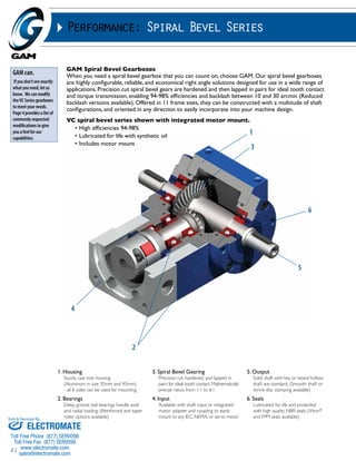
Performance: Spiral Bevel Series
Recommended Output Coupling
VC Series 035 045 065 090 120 140 160 200
bellows KG-5 or KM-4 KG-10 or KM-12 KM-12 or 20 KLC-25 or 50 KLC-50 or 125 KLC-125 or KM-170 KM-170,270 or 400 KM-270,400 or 550
elastomer EKC-5 EKM-8 or 15 EKC-5 or 25 EKC-35 or EKM-45 EKC-80 or 110 EKC-110 or EKM-200 EKM-200,300 or 400 EKM-300,500 or 700
TYPE CODES FOR VC SERIES / LL SERIES
Example: VC - W - 090 - 002 S - [115 - 2AA] - 1-S1-2500-E1-S111
Gearbox Series
VC - Spiral Bevel
Series (size65-200)
LL “mini” Spiral Bevel
Series (size 35 & 45)
Special Options
Assigned by GAM
Maximum Input Speed
Duty Cycle
S1 = continuous speed
S5 = cyclic
Motor Mount Kit
Assigned by GAM
Gearbox Style
K = Keyed hollow shaft
W = Single output shaft
T = Dual output shaft
S = Smooth hollow output
shaft with shrink disc
(not available in LL)
Gearbox Size
Sold & Serviced By:
035, 045, 065, 090
120, 140, 160, 200
Ratio
1, 1.5, 2, 3, 4, 5, 6
Mounting Configuration
Mounting Configuration
Breather Location
Backlash
S = Standard Backlash
R = Reduced Backlash
Shaft
Output
Hollow
Output
Breather Location
(if required)
TYPE CODES FOR V SERIES / L SERIES
Example: V - 090 - 1:1 - C0 - 750-9.1- E2/S1
Gearbox Series
V - Spiral Bevel
L - “Mini” Spiral
Bevel (size 035
and 045)
Duty Cycle
S1 Continuous
Speed
S5 Cyclic
Breather Location
If applicable
Mounting Side
9 = Standard
Tapped holes on housing
sides 1, 2, 4 and on
output flanges sides 5, 6
Gearbox Size
035, 045, 065, 090,
120, 140, 160, 200,
230, 260, 350
Ratio
1, 1.5, 2, 3, 4, 5, 6
Input Running Speed
0-3000 RPM
Gearbox Model
A0, B0, C0, D0, E0, E0/HSD, F0,
G0, H0, J0, K0, K0/HSD, M0
Mounting
Configuration
1,2,3,4,5,6
ELECTROMATE
Toll Free Phone (877) SERVO98
Toll Free Fax (877) SERV099
www.electromate.com
sales@electromate.com](https://image.slidesharecdn.com/gamcatalog-141001201524-phpapp01/85/Gam-catalog-76-320.jpg)


![100
Selection of Optimum Gearbox for a Cycle Operation (S5)
n2c • i ≤ n1max
T2max ≤ T2B
Jmotor ≈ J1 + ––
JL
i2
Zh = –3–6–0–0––
tcycle
Zh < 1000 => fs = 1.0
1000 < Zh < 1500 => fs = 1.1
1500 < Zh < 2000 => fs = 1.3
2000 < Zh < 3000 => fs = 1.6
3000 < Zh < => fs = 2.0
Data needed before selection
can be performed:
1. Maximum Torque of the motor (T1B)
2. Output profile
3. Desired ratio (i)
4. Inertia of the load (JL)*
5. Inertia of the motor (Jmotor)*
*optional
Selection Criteria for Gearbox:
1. Maximum Output Speed must not exceed the maximum speed rating of the gearbox.
2. Maximum Output Torque must not exceed the maximum torque rating of the gearbox.
3. (optional) Match inertia of the motor to the inertia of the load.
See technical data tables for values of ŋ, n1max, T2B, and J1
Calculation to be performed:
1. Shock Factor (fs)
2. Maximum Output Torque
T2max = T1B • i • fs • ŋ = ________________________
Sizing and Selecting for Couplings and Safety Couplings
Sizing
1. Determine torque (MN)
MN = Ma •
Jload
____________
Jload + Jdrive
• 2.5
2. Verify resonant frequency
fcoupling = Ccoupling
1
____
2›
fdrive = Cdrive •
MN Nominal Torque of Coupling
Ma Acceleration Torque of Motor
C
f Resonant frequency [Hz]
Jmot Motor inertia + 1/2 coupling
Jmoch Load inertia + 1/2 coupling
(Jdrive + Jload)
______________
(Jload • Jload)
inertia [kgm2]
inertia [kgm2]
In general fcoupling ≥ 2 • fdrive
3. Apply operating temperature safety factor only
for elastomer couplings
Operating Temperature < 50ºC 50ºC - 70ºC 70ºC - 90ºC 90ºC - 110ºC > 110ºC
Multiply MN by 1 1.3 1.6 1.8 2
Selecting:
1) Determine series of coupling
2) Determine size of coupling based on MN
3) Verify shaft diameters are within range
Ordering Examples:
(When ordering, please include shaft
sizes and tolerances )
Standard Coupling KM-20
D1 = 14 mm k6
D2 = 1.00˝ +0/-.0005˝, x 1/8˝ keyway
Safety Coupling SKB-30
D1 = 19 mm k6
TA (disengagement torque) = 25 Nm
Drive Shaft Coupling WDS-100
D1 = .500˝ +/- .0005˝
D2 = 32 mm k6
Distance Between Shafts = 915 mm
Sold & Serviced By:
ELECTROMATE
Toll Free Phone (877) SERVO98
Toll Free Fax (877) SERV099
www.electromate.com
sales@electromate.com](https://image.slidesharecdn.com/gamcatalog-141001201524-phpapp01/85/Gam-catalog-100-320.jpg)

This document provides information on gear reducers and related products from GAM. It includes summaries of GAM's highest performance inline planetary gear reducer series, the SPH series, which features helical gears for high torque and precision. Specifications are provided for the various SPH model configurations, which can be customized to meet application needs. The document emphasizes the flexibility, modifications, performance and quality that make the SPH series superior to competitors' products.


