Download to read offline
![Dyna Series - DS-W, DS-H, DS-T, DS-F
D7 H7
L15
L12
f1
D4 H7
L4
L9
Recommended Output Coupling (if necessary)
W1
f2
DS-F
L21
L19
L20
D12 H7
D11 h8
W2
L13 L13
D8
L13
L2
L2
D5 f7
DS-H
L7
D4 H7
L6
L18
L14
L13
L2
L9
D3 g6
L5 L1 L5
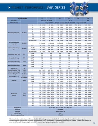
metal bellows KM-60 KM-170 KM-270 KM-400 KM-1300 KSD-2500
elastomer EKM-60 EKM-150 EKM-300 EKM-500 EKM-1000 -
Tolerances (mm)
Size k6 g6 h8 f7 H7 h6
Over 6 +0.010 -0.005 0 -0.013 +0.015 0
Thru 10 +0.001 -0.014 -0.022 -0.028 0 -0.009
Over 10 +0.012 -0.006 0 -0.016 +0.018 0
Thru 18 +0.001 -0.017 -0.027 -0.034 0 -0.011
Over 18 +0.015 -0.007 0 -0.02 +0.021 0
Thru 30 +0.002 -0.020 -0.033 -0.041 0 -0.013
Over 30 +0.018 -0.009 0 -0.025 +0.025 0
Thru 50 +0.002 -0.025 -0.039 -0.05 0 -0.016
Over 50 +0.021 -0.010 0 -0.03 +0.030 0
Thru 80 +0.002 -0.029 -0.046 -0.06 0 -0.019
Over 80 +0.025 -0.012 0 -0.036 +0.035 0
Thru 120 +0.003 -0.034 -0.054 -0.021 0 -0.022
Over 120 +0.028 -0.014 0 -0.043 +0.040 0
Thru 180 +0.003 -0.039 -0.063 -0.083 0 -0.025
Special Options
Assigned by GAM
Motor Mount Kit
Assigned by GAM
Options Available for This Product
LOW OUTPUT
TYPE CODES FOR DYNA SERIES
Example: DS - W B - 090 - 005 G - [115-201] - S111
Gearbox Series
DS = Dyna Series
DSX = Dyna Series Extreme
OPTION BACKLASH KEYWAY
A= Y N
C= Y Y
G= N Y
H= N N
Gearbox Style
W = Single output shaft
T = Dual output shaft
H = Hollow output shaft
F = Flange output
Input Type
B = Bellows coupling input
E = Elastomer coupling input
L = Shaft input
Gearbox Size
055, 075, 090, 115, 130, 140, 160, 190
Ratio
003, 004, 005, 006, 008, 010,
012, 015, 030, 040, 050, 070, 100
Options C and G N/A for DS-F/H models.
Contact GAM for DSX Drawings
53 For more information, call us toll-free at 888-GAM-7117 | Visit www.gamweb.com for 2-D and 3-D Drawings
L11
D1
L13 L5 L1
L10
D3 g6
L5
L14
L2
L13
D8
L13 L13
L10
D2 k6
D2 k6
DS-T
L16
L3
L8
L3
L8
f3
DS-W
D2 k6
D9 k6
L17 f1
L15
L3
f3
L9
L8
L12
L12
L11
D1](https://image.slidesharecdn.com/gamdynaseriesbrochure-141001201154-phpapp02/85/Gam-dyna-series-brochure-5-320.jpg)
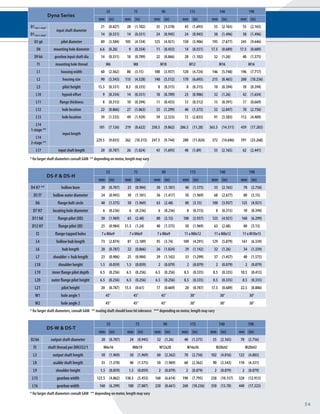

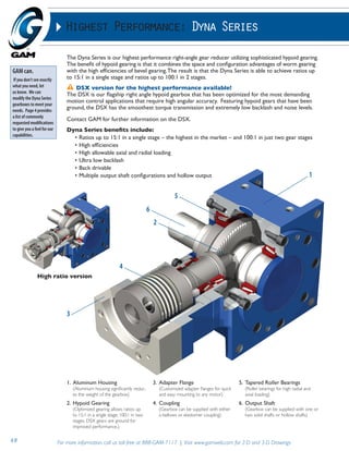
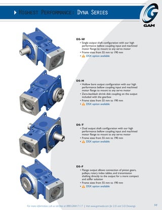
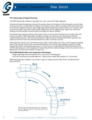
The Dyna Series is the highest performance right-angle gear reducer from GAM, utilizing hypoid gearing that achieves high efficiencies and ratios up to 15:1 in a single stage or 100:1 in two stages. The flagship DSX model features ground hypoid gears for smooth torque transmission, low backlash, and noise. Dyna Series gearboxes are available in multiple configurations including single shaft, hollow bore, dual shaft, and flange output models.


![5G Explained! A High Level Overview [Introduction]](https://cdn.slidesharecdn.com/ss_thumbnails/5gexplainedahighleveloverview-260119165306-cc137a3e-thumbnail.jpg?width=640&height=640&fit=bounds)


