


![https://mvp.in.tum.de Machine Vision and Perception Group IPAM Workshop I, Oct 7, 2020
21
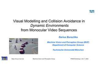
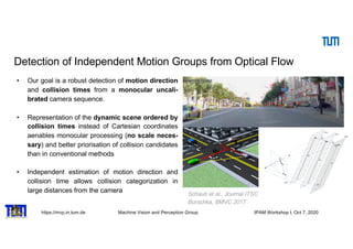
Navigation for Control
VINS filter design [Schmid et al. IROS 2012]
Synchronization of real-time and non realtime modules by sensor hardware trigger
Direct system state:
High rate calculation by „Strap Down Algorithm“ (SDA)
Indirect system state:
Estimation by indirect Extended Kalman Filter (EKF)](https://image.slidesharecdn.com/burschkaipam-201009161243/85/Visual-Mapping-and-Collision-Avoidance-Dynamic-Environments-in-Dynamic-Environments-21-320.jpg)


![https://mvp.in.tum.de Machine Vision and Perception Group IPAM Workshop I, Oct 7, 2020
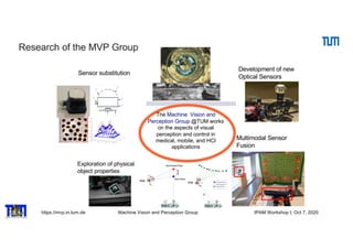
Collaborative Reconstruction with Self-Localization (CVP2008)
Vision in Action: Efficient straegies for
cognitive agents in complex envirnments)
4 Darius Burschka
Fig. 2. Collaborative 3D reconstruction from 2 independently moving cameras.
directional system with a large field of view.
Fig. 3. Single viewpoint
property.
We decided to use omnidirectional systems in-
stead of fish-lens cameras, because their single view-
point property [2] is essential for our combined
localization and reconstruction approach (Fig. 3).
This property allows an easy recovery of the viewing
angle of the virtual camera with the focal point F
(Fig. 3) directly from the image coordinates (ui, νi).
A standard perspective camera can be mapped on
our generic model of an omnidirectional sensor. The
only limitation of a standard perspective camera is
the limited viewing angle. In case of a standard per-
spective camera with a focal point at F, we can es-
timate the direction vector ni of the incoming rays
from the uni-focal image coordinates (focal length
of the camera f=1) (ui, νi) to
method which can be replaced by our robust 3D estimate described in section 2.1.
This mode is necessary in cases, where the required configuration of the cameras
causes occlusions between the agents although the target is still in view of both
cameras.
Our approach offers a robust initialization method for the system presented
in [3]. The original approach relied on an essential method to initialize the
3D structure in the world. Our system gives a more robust initialization method
minimizing the image error directly. The limited space of this paper does not
allow a detailed description of this part of the system. The recursive approach
from [3] is used to maintain the radial distance λx.
3 Results
Our flying systems use omnidirectional mirrors like the one depicted in Fig. 6
Fig. 6. Flying agent equipped with an omnidirectional sensor pointing upwards.
We tested the system on several indoor and outdoor sequences with two cam-
eras observing the world through different sized planar mirrors (Fig. 4) using a
Linux laptop computer with a 1.2 GHz Pentium Centrino processor. The system
was equipped with 1GB RAM and was operating two Firewire cameras with
standard PAL resolution of 768x576.
3.1 Accuracy of the Estimation of Extrinsic Parameters
We used the system to estimate the extrinsic motion parameters and achieved
results comparable with the extrinsic camera calibration results. We verified
the parameters by applying them to the 3D reconstruction process in (5) and
achieved measurement accuracy below the resolution of our test system. This
reconstruction was in the close range of the system which explains the high
inria-00325805,version1-30Sep2008
property. timate the direction vector ni of the incoming rays
from the uni-focal image coordinates (focal length
of the camera f=1) (ui, νi) to
ni =
(ui, νi, 1)T
||(ui, νi, 1)T ||
. (2)
We rely on the fact that each camera can see the partner and the area that it
wants to reconstruct at the same time.
In our system, Camera 1 observes the position of the focal point F of Cam-
era 2 along the vector T , and the point P to be reconstructed along the vector V1
simultaneously (Fig. 2). The second camera (Camera 2) uses its own coordinate
frame to reconstruct the same point P along the vector V2. The point P observed
by this camera has modified coordinates [10]:
V2 = R ∗ (V1 + T ) (3)
inria-0032580
Collaborative Exploration - Vision in Action
Since we cannot rely on any extrinsic calibration, we perform the calibratio
of the extrinsic parameters directly from the current observation. We need t
find the transformation parameters (R, T) in (3) defining the transformatio
between the coordinate frames of the two cameras. Each camera defines its ow
coordinate frame.
2.1 3D Reconstruction from Motion Stereo
In our system, the cameras undergo an arbitrary motion (R, T ) which result
in two independent observations (n1, n2) of a point P. The equation (3) can b
written using (2) as
λ2n2 = R ∗ (λ1n1 + T ). (4
We need to find the radial distances (λ1, λ2) along the incoming rays to estimat
the 3D coordinates of the point. We can find it by re-writing (4) to
(−Rn1, n2)
λ1
λ2
= R · T
λ1
λ2
= (−Rn1, n2)
−∗
· R · T = D−∗
· R · T
(5
We use in (5) the pseudo inverse matrix D−∗
to solve for the two unknown ra
dial distances (λ1, λ2). A pseudo-inverse matrix to D can be calculated accordin
to
Sep2008
Collaborative Exploration - Vision in Action 5
Since we cannot rely on any extrinsic calibration, we perform the calibration
of the extrinsic parameters directly from the current observation. We need to
find the transformation parameters (R, T) in (3) defining the transformation
between the coordinate frames of the two cameras. Each camera defines its own
coordinate frame.
2.1 3D Reconstruction from Motion Stereo
In our system, the cameras undergo an arbitrary motion (R, T ) which results
in two independent observations (n1, n2) of a point P. The equation (3) can be
written using (2) as
λ2n2 = R ∗ (λ1n1 + T ). (4)
We need to find the radial distances (λ1, λ2) along the incoming rays to estimate
the 3D coordinates of the point. We can find it by re-writing (4) to
(−Rn1, n2)
λ1
λ2
= R · T
λ1
λ2
= (−Rn1, n2)
−∗
· R · T = D−∗
· R · T
(5)
We use in (5) the pseudo inverse matrix D−∗
to solve for the two unknown ra-
dial distances (λ1, λ2). A pseudo-inverse matrix to D can be calculated according
to
D−∗
= (DT
· D)−1
· DT
. (6)
The pseudo-inverse operation finds a least square approximation satisfying the
overdetermined set of three equations with two unknowns (λ1, λ2) in (5). Due
to calibration and detection errors, the two lines V1 and V2 in Fig. 2 do not
necessarily intersect. Equation (5) calculates the position of the point along
ersion1-30Sep2008
Collaborative Exploration - Vision in Action 5
Since we cannot rely on any extrinsic calibration, we perform the calibration
of the extrinsic parameters directly from the current observation. We need to
find the transformation parameters (R, T) in (3) defining the transformation
between the coordinate frames of the two cameras. Each camera defines its own
coordinate frame.
2.1 3D Reconstruction from Motion Stereo
In our system, the cameras undergo an arbitrary motion (R, T ) which results
in two independent observations (n1, n2) of a point P. The equation (3) can be
written using (2) as
λ2n2 = R ∗ (λ1n1 + T ). (4)
We need to find the radial distances (λ1, λ2) along the incoming rays to estimate
the 3D coordinates of the point. We can find it by re-writing (4) to
(−Rn1, n2)
λ1
λ2
= R · T
λ1
λ2
= (−Rn1, n2)
−∗
· R · T = D−∗
· R · T
(5)
We use in (5) the pseudo inverse matrix D−∗
to solve for the two unknown ra-
dial distances (λ1, λ2). A pseudo-inverse matrix to D can be calculated according
to
D−∗
= (DT
· D)−1
· DT
. (6)
The pseudo-inverse operation finds a least square approximation satisfying the
overdetermined set of three equations with two unknowns (λ1, λ2) in (5). Due
to calibration and detection errors, the two lines V1 and V2 in Fig. 2 do not
necessarily intersect. Equation (5) calculates the position of the point along
each line closest to the other line.
We notice the similarity between the equations (1) and (5). Equation (1)
can be written to solve for the unknown distance Z from the image plane of the
coplanar binocular stereo system to:
325805,version1-30Sep2008](https://image.slidesharecdn.com/burschkaipam-201009161243/85/Visual-Mapping-and-Collision-Avoidance-Dynamic-Environments-in-Dynamic-Environments-24-320.jpg)
![https://mvp.in.tum.de Machine Vision and Perception Group IPAM Workshop I, Oct 7, 2020
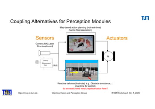
Asynchronous Stereo for Dynamic Scenes
4 Darius Burschka
Fig. 2. Collaborative 3D reconstruction from 2 independently moving cameras.
directional system with a large field of view.
Fig. 3. Single viewpoint
property.
We decided to use omnidirectional systems in-
stead of fish-lens cameras, because their single view-
point property [2] is essential for our combined
localization and reconstruction approach (Fig. 3).
This property allows an easy recovery of the viewing
angle of the virtual camera with the focal point F
(Fig. 3) directly from the image coordinates (ui, νi).
A standard perspective camera can be mapped on
our generic model of an omnidirectional sensor. The
only limitation of a standard perspective camera is
the limited viewing angle. In case of a standard per-
spective camera with a focal point at F, we can es-
timate the direction vector ni of the incoming rays
from the uni-focal image coordinates (focal length
of the camera f=1) (ui, νi) to
ni =
(ui, νi, 1)T
||(ui, νi, 1)T ||
. (2)
inria-00325805,version1-30Sep2008
NTP
Figure 2: Here: C0 and C1 are the camera centers of the
stereo pair, P0,P1,P2 are the 3D poses of the point at times
t0,t1,t2. Latter correspond to frame acquisition timestamps
of camera C0. P⇤ is the 3D pose of the point at time t⇤,
which correspond to the frame acquisition timestamp of the
camera C1. Vectors v0,v1,v2, are unit vectors pointing from
camera center C0, to corresponding 3D points. Vector v⇤ is
the unit vector pointing from camera center C1 to pose P⇤
and the unit vector v3 is the velocity direction vector.
Here a = acos(v0 ·v1) and b = acos(v2 ·v1). First
we write law of sines for the triangles 4P0COP1 and
Since the angle between the velocity direction
vector v3 and v0 is y, v3 and v2 is h, and v2 and
ˆn is p
2 . We can compute the v3 by solving the follow-
ing equation:
2
4
v0x v0y v0z
v2x v2y v2z
nx ny nz
3
5
2
4
v3x
v3y
v3z
3
5 =
2
4
cosy
cosh
0
3
5
(7)
3.2 Path Reconstruction
In the second stage of proposed method we compute
the 3D pose P0. For reasons of simplicity we will
represent the poses (Pi (i = 0..2), P⇤) depicted in Fig.
2 as:
Pi =
2
4
ai ⇤zi
bi ⇤zi
zi
3
5 P⇤ =
2
4
m⇤z⇤
0 +tx
s⇤z⇤
0 +ty
q⇤z⇤
0 +tz
3
5 (8)
where tx,ty,tz are the x,y and z components of
the translation vector between the cameras, ai = vix
viz
,
bi =
viy
viz
are the x and y components of the vi (i = 0..2)
direction vectors Figure 2, and:
2 ⇤ 3
Mkhitaryan, Burschka VISAPP 2014
MVP](https://image.slidesharecdn.com/burschkaipam-201009161243/85/Visual-Mapping-and-Collision-Avoidance-Dynamic-Environments-in-Dynamic-Environments-25-320.jpg)


![https://mvp.in.tum.de Machine Vision and Perception Group IPAM Workshop I, Oct 7, 2020
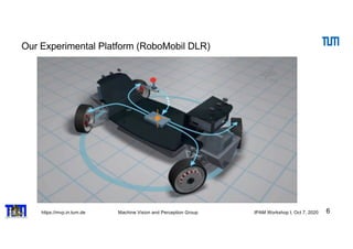
Optimal Feature Selection
33
III. SYSTEM ANALYSIS
The relative error in the solution caused by perturbations
of parameters can be estimated from the condition number
of the Image Jacobian matrix J. The condition number
is the ratio between the largest and the smallest singular
value of the matrix J.
The condition number estimates the sensitivity of solu-
tion of a linear algebraic system to variations of parame-
ters in matrix J and in the measurement vector b.
Consider the equation system with perturbations in
matrix J and vector b:
(J + δJ )xb = b + δb (7)
The relative error in the solution caused by perturbations
of parameters can be estimated by the following inequality
using the condition number κ calculated for J (see [5]):
||x − xb||
||x||
≤ κ
||δJ ||
||J ||
+
||δb||
||b||
+ O( 2
) (8)
Therefore, the relative error in solution x can be as large
as condition number times the relative error in J and b. The
condition number together with the singular values of the
matrix J describe the sensitivity of the system to changes
in the input parameters.
In the following subsections we investigate the observ-
ability and accuracy of the output parameters (x, y, z)
from the input stream of the camera system (sec. III-
A) and the influence of the real sensor on the achievable
accuracy of the system (sec. III-B).
A. Optimal Landmark Configuration for the Image Jaco-
bian Matrix
The singular values can be obtained as positive square
roots of the eigenvalues of the matrix JT
· J. With
yi∈{1,...,N} as heights of the tracked objects, αi∈{1,...,N}
as azimuth angles to them and βi∈{1,...,N} as their eleva-
tion angles. The resulting matrix for N landmarks has the
form shown in (9).
ri = x2
i
From th
directly for
∆r, the err
the value
Since in
space, the
the recipro
0
0.05
0.1
0.15
0.2
0.25
0.3
We dedu
placement
expression
∆r. The o
dκr
dyi
⇒
that corres
It is sho
solution co
J t
i =
∂αi
∂x
∂αi
∂z
∂αi
∂Θ
∂βi
∂x
∂βi
∂z
∂βi
∂Θ
=
zi
x2
i
+z2
i
− xi
x2
i
+z2
i
−1
− xiyi
(x2
i
+y2
i
+z2
i
)·
√
x2
i
+z2
i
− yizi
(x2
i
+y2
i
+z2
i
)·
√
x2
i
+z2
i
0
(2)
The dependency on the unknown position (xi, zi) of
the robot relative to the tracked landmark can be avoided
considering the geometry of the system to:
x2
i + y2
i + z2
i = yi
sin βi
, x2
i + z2
i = yi
tan βi
,
xi = yi·sin αi
tan βi
, zi = yi·cos αi
tan βi
J t
i =
tan βi·cos αi
yi
−tan βi·sin αi
yi
−1
−sin2
βi·sin αi
yi
−sin2
βi·cos αi
yi
0
(3)
Note in particular that the Image Jacobian is a function
of only one unobserved parameter, yi, the height of the
observed point. Furthermore, this value is constant for
motion in the plane. Thus, instead of estimating a time-
changing quantity as is the case in most vision-based
control, we only need to solve a simpler static estimation
problem. We refer to [3] for a detailed description of the
yi-estimation.
In the following text we assume that the system already
learned the positions of the tracked objects as columns
in a matrix Mp in the teaching phase [3]. In the replay
)−1
J tT
(6)
position
robot.
rbations
number
number
singular
of solu-
parame-
an orientation ∆Θ relative to it. The equation (3) can then
be written in this case as:
J t
i =
0 −1
−sin2
βi
yi
0
=
0 −1
− 1
yi· 1+
ri
yi
2
0
ri = x2
i + z2
i
(10)
From the equation (10) we learn that an error ∆Θ is
directly forwarded to the output value αi, while the value
∆r, the error in the distance to the feature, is scaled with
the value
κr = y · 1 +
ri
yi
2 −1
(11)
∆wt
= (J t
)−1
·∆et
, with (J t
)−1
= (J tT
J t
)−1
J tT
(6)
The value ∆wt
describes the error in the 3D position
that we use to generate the control signals for the robot.
III. SYSTEM ANALYSIS
The relative error in the solution caused by perturbations
of parameters can be estimated from the condition number
of the Image Jacobian matrix J. The condition number
is the ratio between the largest and the smallest singular
value of the matrix J.
The condition number estimates the sensitivity of solu-
tion of a linear algebraic system to variations of parame-
ters in matrix J and in the measurement vector b.
Consider the equation system with perturbations in
matrix J and vector b:
(J + δJ )xb = b + δb (7)
The relative error in the solution caused by perturbations
of parameters can be estimated by the following inequality
using the condition number κ calculated for J (see [5]):
||x − xb||
||x||
≤ κ
||δJ ||
||J ||
+
||δb||
||b||
+ O( 2
) (8)
Therefore, the relative error in solution x can be as large
as condition number times the relative error in J and b. The
condition number together with the singular values of the
matrix J describe the sensitivity of the system to changes
in the input parameters.
an orientation ∆Θ relative to it. The equation (3) can then
be written in this case as:
J t
i =
0 −1
−sin2
βi
yi
0
=
0 −1
− 1
yi· 1+
ri
yi
2
0
ri = x2
i + z2
i
(10)
From the equation (10) we learn that an error ∆Θ is
directly forwarded to the output value αi, while the value
∆r, the error in the distance to the feature, is scaled with
the value
κr = y · 1 +
ri
yi
2 −1
(11)
Since in our case the measurement error is in the image
space, the resulting errors in the world are dependent on
the reciprocal values.
0 2 4 6 8 10 12 14 16 18 20
0.05
0.1
0.15
0.2
0.25
0.3
y
κr
r
is the ratio between the largest and the smallest singular
value of the matrix J.
The condition number estimates the sensitivity of solu-
tion of a linear algebraic system to variations of parame-
ters in matrix J and in the measurement vector b.
Consider the equation system with perturbations in
matrix J and vector b:
(J + δJ )xb = b + δb (7)
The relative error in the solution caused by perturbations
of parameters can be estimated by the following inequality
using the condition number κ calculated for J (see [5]):
||x − xb||
||x||
≤ κ
||δJ ||
||J ||
+
||δb||
||b||
+ O( 2
) (8)
Therefore, the relative error in solution x can be as large
as condition number times the relative error in J and b. The
condition number together with the singular values of the
matrix J describe the sensitivity of the system to changes
in the input parameters.
In the following subsections we investigate the observ-
ability and accuracy of the output parameters (x, y, z)
from the input stream of the camera system (sec. III-
A) and the influence of the real sensor on the achievable
accuracy of the system (sec. III-B).
A. Optimal Landmark Configuration for the Image Jaco-
bian Matrix
The singular values can be obtained as positive square
roots of the eigenvalues of the matrix JT
· J. With
yi∈{1,...,N} as heights of the tracked objects, αi∈{1,...,N}
as azimuth angles to them and βi∈{1,...,N} as their eleva-
tion angles. The resulting matrix for N landmarks has the
form shown in (9).
The system estimates three parameters (dx, dy, dΘ)
from the image positions (ui, vi) of all tracked primitives
(features) i ∈ {1, . . . , N} (4). Therefore, at least two fea-
tures are necessary to estimate all 3 position parameters.
Each feature contributes a measurement of a distance
∆ri from the robot to the feature in the ground plane and
the value
κr = y · 1 +
ri
yi
2 −1
(11)
Since in our case the measurement error is in the image
space, the resulting errors in the world are dependent on
the reciprocal values.
0 2 4 6 8 10 12 14 16 18 20
0.05
0.1
0.15
0.2
0.25
0.3
y
κr
r
Fig. 3. Dependency of κr on yi and ri.
We deduce from the above equation that the optimum
placement of the feature should maximize the above
expression to allow good observability of the position error
∆r. The optimal value can be estimated to
dκr
dyi
= −
1
xi
2 1 + ri
2
yi
2
+
2 · ri
2
yi
4 1 + ri
2
yi
2
2 = 0
⇒ yi = ±ri ⇒ βi = arctan
yi
ri
(12)
that corresponds to an angle |βi| = 45◦
.
It is shown that any linear system has at least one
solution component whose sensitivity to perturbations is
proportional to the condition number of the matrix, but
there may exist many components that are much better
conditioned [4]. The sensitivity for different components
of the solution changes depending on the configuration
of the landmarks and the relative position of the robot to
them.](https://image.slidesharecdn.com/burschkaipam-201009161243/85/Visual-Mapping-and-Collision-Avoidance-Dynamic-Environments-in-Dynamic-Environments-33-320.jpg)

![https://mvp.in.tum.de Machine Vision and Perception Group IPAM Workshop I, Oct 7, 2020
Are lab approaches transferrable to automobile and avionic
applications?
Sensitivity increase:
• Larger baseline (B)
• Longer focal length (f)
field of view
• Smaller pixelsize (px)
“pixel explosion”
d p =
B⋅ f
px
⋅
1
z
pixel[ ]
75cm](https://image.slidesharecdn.com/burschkaipam-201009161243/85/Visual-Mapping-and-Collision-Avoidance-Dynamic-Environments-in-Dynamic-Environments-35-320.jpg)
![https://mvp.in.tum.de Machine Vision and Perception Group IPAM Workshop I, Oct 7, 2020
Direct Mapping of Point Motion on Image
Observation
estimate the collision property.
A three-dimensional point Pi travels with an arbitrary constant velocity vector vgi
in Fig. 5. This motion results in a trace of tracked points pi in consecutive image
frames for time steps t={0,1,2}. The vector vgi defines a plane containing Pi. We
call this a collision plane which sweeps through the focal point of the camera after
some. The collision time can be estimated from the trace of the point [9].
t=0
t=1
t=2
k vgi
Vgi
PI
Ei
PI
Vgi
H
H
H
Fig. 5 A 3D point Pi travels in three frames t=0,1,2 with a velocity vgi. The vector vgi with the
point Pi defines a gray collision plane with vgi as its normal vector.](https://image.slidesharecdn.com/burschkaipam-201009161243/85/Visual-Mapping-and-Collision-Avoidance-Dynamic-Environments-in-Dynamic-Environments-36-320.jpg)


![https://mvp.in.tum.de Machine Vision and Perception Group IPAM Workshop I, Oct 7, 2020
Identification of Interaction Regions in the Scene
43
nt
es
of
rts
ly
er-
of
ze
ng
nd
ta
ng
a-
e-
nt
al-
ze
es,
nd
8]
ar
ay
up
by
on
Kitani et al. [26] infer future long-term walking paths
from the physical world with obstacles and preferred areas as
sidewalks but do not analyze temporal evolution after initial
estimation like this approach.
Fig. 2. Map data is enriched by interaction regions(orange) caused by static
POI (entrances to shops, narrows) (green), dynamic intersection regions
(blue) based on intersecting trajectories. Pictured area of second example.
III. APPROACH
Our approach is divided into three parts: First, a static
map of Points and Areas of Interest (POI/AOI) is computed
offline beforehand (Figure 2), which is used for local
search of possible long term goals in a given scenario. It is
extended on-line if temporary changes occur in a scenario,
e.g. construction works on or next to the street.
Second, possible dynamic areas of interaction are calcu-
lated on-line with possible paths and occupation times for
circulation. For review only.
Extraction of map-based POI
static
Pedestrian Intention Detection as a Resource Competition Challenge
Peter Gawronski1 Darius Burschka2
Abstract— We propose an approach to classify possible in-
teraction types between autonomous vehicles and pedestrians
based on the idea of resource competition in shared spaces.
Autonomous vehicles are more challenged in urban traffic
scenarios as lots of uncertainties influence the current world
model. Urban environments impose very little constraints on
the motion of pedestrians. This creates the demand for an
approach to determine intentions for each pedestrian as far
ahead as possible and to react to changes early. A motion model
based on goal-driven pedestrian movement shows a set of most
likely planned trajectories. These are analyzed for overlapping
occupation times in road segments, thus interactions with the
vehicle. The output is an early estimation which suggests most
probable interaction types and places. From this estimation,
current trajectory of the pedestrian is used to refine the
prediction of the most probable intention of interaction place
and type. In the end the algorithm combines topological and
behavioral input to infer and validate long term intention
of interaction type before being able to actually infer the
interaction from current dynamics.
In terms of a proof-of-concept, the applicability of the ap-
proach is validated on real world scenarios from the Cityscapes
data set.
Fig. 1. Person starting to run towards an intersection: Changes in behavior
indicate a change of mind and thus a new interaction type. Highlighted
interaction area based on the temporal resource competition analysis.
Scenario 3, cutout of frame 19997
3. Very similar behavior can have different causes and
outcomes, as pedestrian movement is not limited very much,
thus changes in trajectory and intention happen very quickly.
4. Traffic participants in a scene influence each other by
changes in behavior so that most often a seamless interaction
is achieved, sometimes aided by visual clues.
There is a lot of research for solutions to estimate pedestri-
CONFIDENTIAL. Limited circulation. For review only.
Identification of overlapping ”resource” allocation (competition
for POI) dynamic](https://image.slidesharecdn.com/burschkaipam-201009161243/85/Visual-Mapping-and-Collision-Avoidance-Dynamic-Environments-in-Dynamic-Environments-43-320.jpg)
![https://mvp.in.tum.de Machine Vision and Perception Group IPAM Workshop I, Oct 7, 2020
Estimation of Intention of the Traffic Agents
44
includes a road network to identify intersections of roads at
which interactions between motorists will occur most likely,
but is feasible for pedestrian movement as to determine
movement across the road. Furthermore, static infrastructure
can be plotted into the database such as crosswalks, sig-
nalized crossings or narrow passages in low density urban
areas. It is merged with destinations of travel in the scene
as crossroads to another street, entries to parking lots shops
or areas of shared space, e.g. a pedestrian headed towards a
crosswalk.
a) Influences of topology: Figure 3 shows some typical
topologies and how they influence behavior. In all scenarios,
the hypothetical arrival and occupation time is calculated for
the pedestrian as depicted on the left. The vehicle is limited
to the road, but may change lanes or turn.
A long term goal may influence behavior and trajectory of
a pedestrian, as different paths lead to the same goal and
non-interference with cars may be intended. Third example
includes crosswalk and thus creates a strong goal as crossing
is safer there and makes jaywalking less probably.
The last example shows a possible situation at a corner.
Arrival time of the pedestrian is identical for both crossings,
an interaction with the vehicle depending on the unknown
goal. Temporal analysis is needed to evaluate further.
resource, e.g. an area at which trajectories meet, as simul-
taneous usage is not possible, shown in Figure 1 in red.
This limitation is used for behavior prediction as some form
of reaction is needed to avoid a collision, either by change
of velocity or direction by one or more of the participants
involved. A planned solution may exist, as with right-of-
way, but changes in behavior may solve these differently than
anticipated, e.g. the yielding object accelerating to avoid the
yield situation, as in scenario 3.
Fig. 4. Schematic behavior patterns in a interaction scenario: 1/2: vehicle
passing behind/in front of the pedestrian from a collision situation, 3:
passive pedestrian; 4: assertive crossing; 5/6/7: changes in velocity which
may influence outcome, 8/9: pedestrian turning away/towards the road as
indicators against/for crossing intention. Details in chapter III-C.
C. Temporal Analysis of Behavior
A temporal analysis is performed to analyze the behavior
and predict which of previously estimated probable actions
is performed. Both objects involved use nonverbal commu-
nication in form of clear changes in TTA by changes in
velocity and/or direction to clear an interfering situation.
Temporal evolution of TTC at the resource
allows to assess passivity of aggressivity of
the traffic partner
to the road, but may change lanes or turn.
A long term goal may influence behavior and trajectory of
a pedestrian, as different paths lead to the same goal and
non-interference with cars may be intended. Third example
includes crosswalk and thus creates a strong goal as crossing
is safer there and makes jaywalking less probably.
The last example shows a possible situation at a corner.
Arrival time of the pedestrian is identical for both crossings,
an interaction with the vehicle depending on the unknown
goal. Temporal analysis is needed to evaluate further.
Fig. 3. Schematic overview of influences of POI to pedestrian movement:
Possible walking paths for a pedestrian (orange) and the ego vehicle (purple)
and found POI in range (green). LTR: no POI in area; possible paths to
cross the road; introducing crosswalks/right of way; different options create
different situations
b) Occupation times: To compensate for input noise
and the fact that the whole area must be cleared of obstruc-
tions before safe passage is possible, some buffer around
arrival times must be considered. Direct collision is consid-
ered at TTA 0.5s, close calls at TTA 2s, both of
which are to be avoided.
Fig. 4. Schematic behavior patterns in a interaction scenario: 1/2: vehicle
passing behind/in front of the pedestrian from a collision situation, 3:
passive pedestrian; 4: assertive crossing; 5/6/7: changes in velocity which
may influence outcome, 8/9: pedestrian turning away/towards the road as
indicators against/for crossing intention. Details in chapter III-C.
C. Temporal Analysis of Behavior
A temporal analysis is performed to analyze the behavior
and predict which of previously estimated probable actions
is performed. Both objects involved use nonverbal commu-
nication in form of clear changes in TTA by changes in
velocity and/or direction to clear an interfering situation.
Pedestrians may give visual clues to a driver [11], but as
these are not always clear, especially in-camera due to low
resolution, and also they can go unnoticed or misinterpreted
by an algorithmic detector, they are not taken into account
in this work.
In situations of clear legislation, the expected output is
anticipated. Unexpected behavior can have multiple causes
by means of aggressiveness or situation awareness, but
can also be a sign of distraction from the situation. Open
situations can have several outcomes, so the analysis of
movement behavior can pinpoint the moment a decision is
made, especially for the yielding party.
The main information gain is obtained from changes in
velocity, as both responses of acceleration and deceleration
Static and dynamic POI allow a better
prediction of intentions
Changes in the temporal interaction with agents can be used for behavior analysis
(IV 2019)](https://image.slidesharecdn.com/burschkaipam-201009161243/85/Visual-Mapping-and-Collision-Avoidance-Dynamic-Environments-in-Dynamic-Environments-44-320.jpg)


The document discusses the research and developments of the Machine Vision and Perception Group at Technische Universität München, focusing on visual perception and control applications in medical, mobile, and human-computer interaction contexts. It outlines various techniques for monocular visual navigation, including 3D reconstruction and real-time navigation leveraging sensor fusion and optical flow analysis. The workshop also highlights collaborative 3D reconstruction and navigation strategies, emphasizing the advantages of omnidirectional systems over traditional cameras.


![Alan Lucas - [Template] [Template] [Template] ScienceFairProjectTemplate.pptx](https://cdn.slidesharecdn.com/ss_thumbnails/alanlucas-templatetemplatetemplatesciencefairprojecttemplate-260106222421-b6ad9ab7-thumbnail.jpg?width=640&height=640&fit=bounds)


