Download as PDF, PPTX

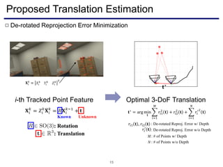
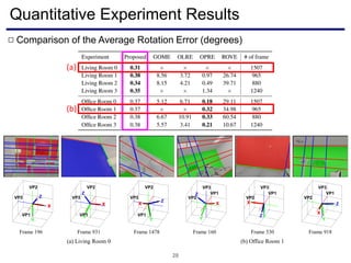
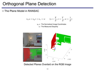
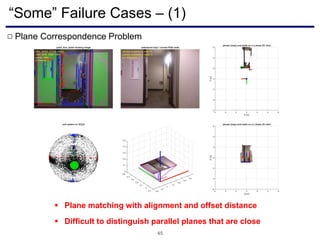
![Quantitative Analysis with True Data
22
Frame Index
TranslationError[m]RotationError[deg]
Rotation error
causes failure
Average rotation
error is ~0.2 deg
On average, 5x
more accurate
15 Hz @ 10 FPS](https://image.slidesharecdn.com/visualodometryslamutilizingindoorstructuredenvironments-181113050523/85/Visual-odometry-slam-utilizing-indoor-structured-environments-22-320.jpg)
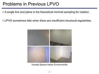
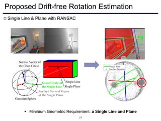
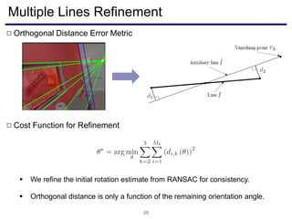
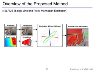
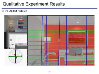

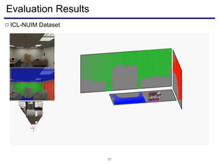
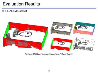
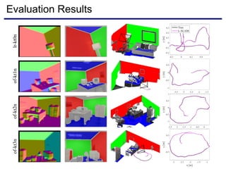
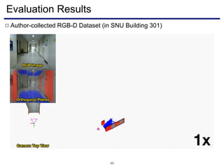
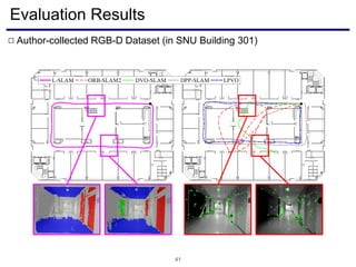
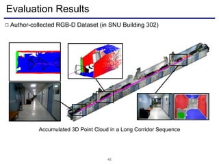
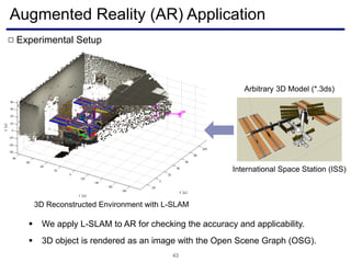
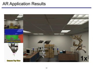


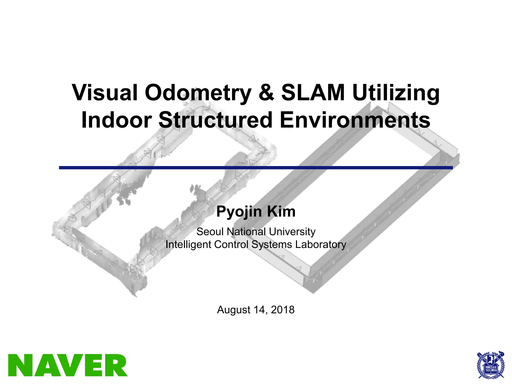
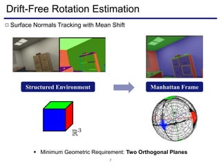
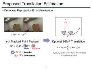
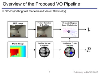
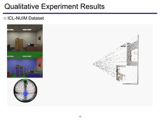
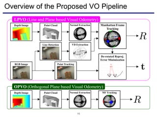
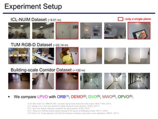
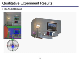
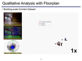
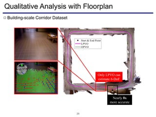
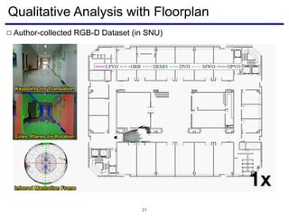
The document discusses a novel approach to visual odometry (VO) and simultaneous localization and mapping (SLAM) that leverages structural information in indoor environments, focusing on drift-free rotation estimation using lines and planes. It presents various algorithms and evaluations, demonstrating the effectiveness of the proposed methods in improving camera orientation and translation accuracy across different datasets. Key contributions include the development of linear SLAM formulations and their applications in augmented reality, addressing challenges in traditional VO and SLAM techniques.


![SSII2020 [O3-01] Extreme 3D センシング](https://cdn.slidesharecdn.com/ss_thumbnails/200612-ssii-extreme3dsensing-print3-200608114658-thumbnail.jpg?width=640&height=640&fit=bounds)


![지리정보체계(GIS) - [1] GIS 데이터 유형, 구조 알기](https://cdn.slidesharecdn.com/ss_thumbnails/sugis2018c01-180902151613-thumbnail.jpg?width=640&height=640&fit=bounds)


![SSII2022 [OS3-04] Human-in-the-Loop 機械学習](https://cdn.slidesharecdn.com/ss_thumbnails/ssii2022-os3-04-220607021031-e69700d5-thumbnail.jpg?width=640&height=640&fit=bounds)