Md. Jakir Hossen
AssistantProfessor
Institute of Energy Engineering
Dhaka University of Engineering & Technology,
Gazipur
Fundamentals of Mechanical
Engineering
EEE-217
2.
2
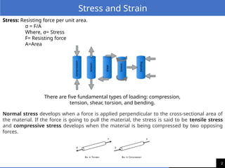
Stress: Resisting forceper unit area.
σ = F/A
Where, σ= Stress
F= Resisting force
A=Area
Stress and Strain
There are five fundamental types of loading: compression,
tension, shear, torsion, and bending.
Normal stress develops when a force is applied perpendicular to the cross-sectional area of
the material. If the force is going to pull the material, the stress is said to be tensile stress
and compressive stress develops when the material is being compressed by two opposing
forces.
3.
3
Stress and Strain
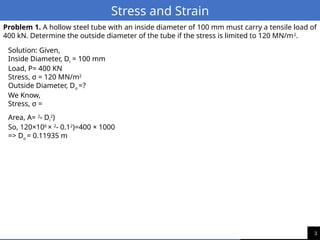
Problem1. A hollow steel tube with an inside diameter of 100 mm must carry a tensile load of
400 kN. Determine the outside diameter of the tube if the stress is limited to 120 MN/m2
.
Solution: Given,
Inside Diameter, Di = 100 mm
Load, P= 400 KN
Stress, σ = 120 MN/m2
Outside Diameter, Do =?
We Know,
Stress, σ =
Area, A= 2
- Di
2
)
So, 120×106
× 2
- 0.12
)=400 × 1000
=> Do = 0.11935 m
4.
4
Stress and Strain
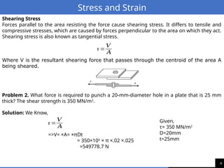
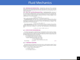
ShearingStress
Forces parallel to the area resisting the force cause shearing stress. It differs to tensile and
compressive stresses, which are caused by forces perpendicular to the area on which they act.
Shearing stress is also known as tangential stress.
Where V is the resultant shearing force that passes through the centroid of the area A
being sheared.
τ =
𝑉
𝐴
Problem 2. What force is required to punch a 20-mm-diameter hole in a plate that is 25 mm
thick? The shear strength is 350 MN/m2
.
Solution: We Know,
τ =
𝑉
𝐴
=>V= ×A= ×πDt
= 350×106
× π ×.02 ×.025
=549778.7 N
Given,
τ= 350 MN/m2
D=20mm
t=25mm
5.
5
Stress and Strain
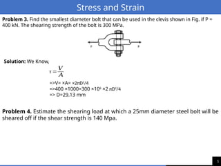
Problem3. Find the smallest diameter bolt that can be used in the clevis shown in Fig. if P =
400 kN. The shearing strength of the bolt is 300 MPa.
Solution: We Know,
τ =
𝑉
𝐴
=>V= ×A= ×2πD2
/4
=>400 ×1000=300 ×106
×2 πD2
/4
=> D=29.13 mm
Problem 4. Estimate the shearing load at which a 25mm diameter steel bolt will be
sheared off if the shear strength is 140 Mpa.
6.
6
Stress and Strain
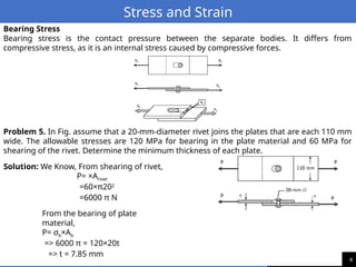
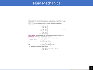
BearingStress
Bearing stress is the contact pressure between the separate bodies. It differs from
compressive stress, as it is an internal stress caused by compressive forces.
Problem 5. In Fig. assume that a 20-mm-diameter rivet joins the plates that are each 110 mm
wide. The allowable stresses are 120 MPa for bearing in the plate material and 60 MPa for
shearing of the rivet. Determine the minimum thickness of each plate.
Solution: We Know, From shearing of rivet,
P= ×Arivet
=60×π202
=6000 π N
From the bearing of plate
material,
P= σb×Ab
=> 6000 π = 120×20t
=> t = 7.85 mm
7.
7
Stress and Strain
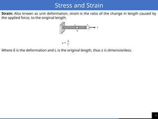
Strain:Also known as unit deformation, strain is the ratio of the change in length caused by
the applied force, to the original length.
Where δ is the deformation and L is the original length, thus ε is dimensionless.
8.
8
Stress and Strain
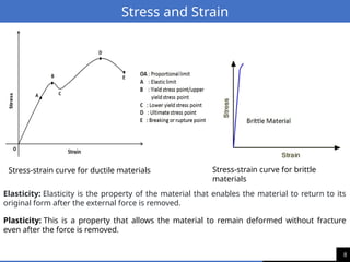
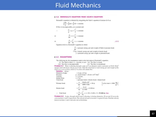
Elasticity:Elasticity is the property of the material that enables the material to return to its
original form after the external force is removed.
Plasticity: This is a property that allows the material to remain deformed without fracture
even after the force is removed.
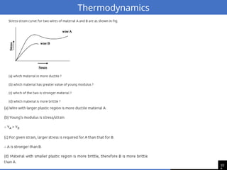
Stress-strain curve for ductile materials Stress-strain curve for brittle
materials
9.
9
Stress and Strain
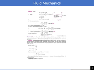
ProportionalLimit (Hooke's Law)
Within the proportional limit (straight line between zero and A), strain is proportionate to
stress.
Elastic Limit
The elastic limit is the limit beyond which the material will no longer go back to its original
shape when the load is removed, or it is the maximum stress that may be developed such that
there is no permanent or residual deformation when the load is entirely removed.
Elastic and Plastic Ranges
The region in the stress-strain diagram from O to A is called the elastic range. The region from
A to D is called the plastic range.
Yield Point
Yield point is the point at which the material will have an appreciable elongation or yielding
without any increase in load.
Ultimate Strength
The maximum ordinate in the stress-strain diagram is the ultimate strength or tensile
strength.
Rapture Strength
Rapture strength is the strength of the material at rupture. This is also known as the breaking
strength.
Creep: Creep is the slow and continuous deformation of a material under a constant stress,
usually at high temperatures.
Fatigue: Fatigue is the progressive and localized damage of a material under cyclic or
fluctuating stress, usually at low or moderate temperatures.
10.
10
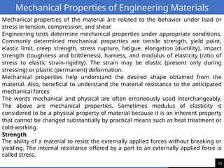
Mechanical Properties ofEngineering Materials
Mechanical properties of the material are related to the behavior under load or
stress in tension, compression, and shear.
Engineering tests determine mechanical properties under appropriate conditions.
Commonly determined mechanical properties are tensile strength, yield point,
elastic limit, creep strength, stress rupture, fatigue, elongation (ductility), impact
strength (toughness and brittleness), harness, and modulus of elasticity (ratio of
stress to elastic strain-rigidity). The strain may be elastic (present only during
stressing) or plastic (permanent) deformation.
Mechanical properties help understand the desired shape obtained from the
material. Also, beneficial to understand the material resistance to the anticipated
mechanical forces
The words mechanical and physical are often erroneously used interchangeably.
The above are mechanical properties. Sometimes modulus of elasticity is
considered to be a physical property of material because it is an inherent property
that cannot be changed substantially by practical means such as heat treatment or
cold-working.
Strength
The ability of a material to resist the externally applied forces without breaking or
yielding. The internal resistance offered by a part to an externally applied force is
called stress.
11.
11
Mechanical Properties ofEngineering Materials
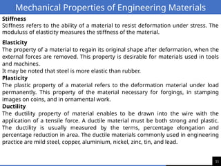
Stiffness
Stiffness refers to the ability of a material to resist deformation under stress. The
moduluss of elasticity measures the stiffness of the material.
Elasticity
The property of a material to regain its original shape after deformation, when the
external forces are removed. This property is desirable for materials used in tools
and machines.
It may be noted that steel is more elastic than rubber.
Plasticity
The plastic property of a material refers to the deformation material under load
permanently. This property of the material necessary for forgings, in stamping
images on coins, and in ornamental work.
Ductility
The ductility property of material enables to be drawn into the wire with the
application of a tensile force. A ductile material must be both strong and plastic.
The ductility is usually measured by the terms, percentage elongation and
percentage reduction in area. The ductile materials commonly used in engineering
practice are mild steel, copper, aluminium, nickel, zinc, tin, and lead.
12.
12
Mechanical Properties ofEngineering Materials
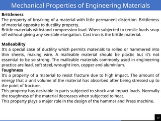
Brittleness
The property of breaking of a material with little permanent distortion. Brittleness
of material opposite to ductility property.
Brittle materials withstand compression load. When subjected to tensile loads snap
off without giving any sensible elongation. Cast iron is the brittle material.
Malleability
It’s a special case of ductility which permits materials to rolled or hammered into
thin sheets, making wire. A malleable material should be plastic but it’s not
essential to be so strong. The malleable materials commonly used in engineering
practice are lead, soft steel, wrought iron, copper and aluminium.
Toughness
It’s a property of a material to resist fracture due to high impact. The amount of
energy that a unit volume of the material has absorbed after being stressed up to
the point of fracture.
This property has desirable in parts subjected to shock and impact loads. Normally
the toughness of the material decreases when subjected to heat.
This property plays a major role in the design of the hammer and Press machine.
13.
13
Mechanical Properties ofEngineering Materials
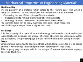
Machinability
It’s the property of a material which refers to the relative ease with which a
material can be cut. The machinability of a material is measured as follows
• Comparing the tool life for cutting different materials
• Thrust required to remove the material at some given rate
• The energy required to remove a unit volume of the material.
For example, brass can be easily machined than steel, which means the
machinability property of brass is higher than steel.
Resilience
It is the property of a material to absorb energy and to resist shock and impact
loads. Resilience measures the amount of energy absorbed per unit volume within
the elastic limit. This property plays a major role in the design of spring materials.
Creep
When material subjected to constant stress at high temperature for a long period
of time, it will undergo a slow and permanent deformation called creep.
This property plays a major role in the design of internal combustion engines,
boilers and turbines.
14.
14
Mechanical Properties ofEngineering Materials
Fatigue
Fatigue is the repeated loading and unloading of metal due to direct load variation,
eccentricity in a rotating shaft, or differential thermal expansion of a structure.
Even substantially below the yield point (elastic limit) of a metal or alloy this
repeated loading can lead to failure, usually measured in terms of the number of
cycles (repeated load applications) to failure.
This property plays a major role in the design of shafts, connecting rods, springs,
gears etc.
Hardness
It is a very important property of metal and has a wide variety of meanings. It
embraces many different properties such as resistance to wear, scratching,
deformation, machinability etc.
Hardness is the ability of materials to resist being permanently deformed when a
load is applied (ie., bent, broken, or shape change). The greater the hardness, the
greater the resistance to deformation.
It also means the ability of a metal to cut another metal. The hardness is usually
expressed in numbers which are dependent on the method of making the test.
The below-listed tests to determine the material hardness
1. Brinell hardness test 2. Rockwell hardness test 3. Vickers hardness (also called
Diamond Pyramid) test 4. Shore scleroscope
15.
15
Mechanical Properties ofEngineering Materials
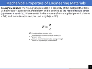
Young’s Modulus: The Young's modulus (E) is a property of the material that tells
us how easily it can stretch and deform and is defined as the ratio of tensile stress
(σ) to tensile strain (ε). Where stress is the amount of force applied per unit area (σ
= F/A) and strain is extension per unit length (ε = dl/l).
16.
16
Mechanical Properties ofEngineering Materials
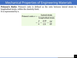
Poisson's Ratio: Poisson's ratio is defined as the ratio between lateral strain to
longitudinal strain, within the elasticity limit.
It is represented by σ.
17.
17
Mechanical Properties ofEngineering Materials
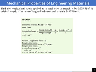
Find the longitudinal stress applied to a steel wire to stretch it by 0.025 % of its
original length, if the ratio of longitudinal stress and strain is 9×10¹⁰
Nm 2
−
.
18.
18
Mechanical Properties ofEngineering Materials
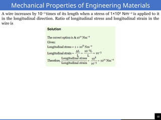
A wire increases by 10 3
−
times of its length when a stress of 1×10⁸
Nm 2
−
is applied to it
in the longitudinal direction. Ratio of longitudinal stress and longitudinal strain in the
wire is
19.
19
Mechanical Properties ofEngineering Materials
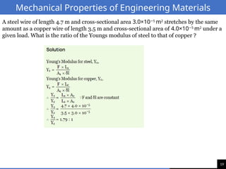
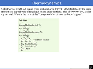
A steel wire of length 4.7 m and cross-sectional area 3.0×10 5
−
m2
stretches by the same
amount as a copper wire of length 3.5 m and cross-sectional area of 4.0×10 5
−
m2
under a
given load. What is the ratio of the Youngs modulus of steel to that of copper ?
20.
20
Heat
Heat is aform of energy.
• Heat travels from higher temperature(hotter) region to lower temperature(cooler) region.
• Two bodies are in thermal equilibrium when no net thermal energy transfer exists.
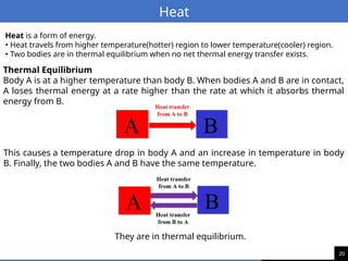
Thermal Equilibrium
Body A is at a higher temperature than body B. When bodies A and B are in contact,
A loses thermal energy at a rate higher than the rate at which it absorbs thermal
energy from B.
This causes a temperature drop in body A and an increase in temperature in body
B. Finally, the two bodies A and B have the same temperature.
They are in thermal equilibrium.
21.
21
Heat
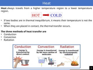
Heat always travelsfrom a higher temperature region to a lower temperature
region.
• If two bodies are in thermal inequilibrium, it means their temperature is not the
same.
• When they are placed in contact, the thermal transfer occurs.
The three methods of heat transfer are
• Conduction
• Convection
• Radiation
22.
22
Heat
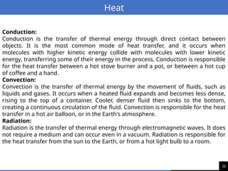
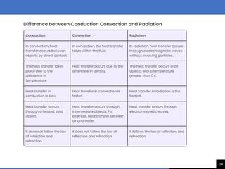
Conduction:
Conduction is thetransfer of thermal energy through direct contact between
objects. It is the most common mode of heat transfer, and it occurs when
molecules with higher kinetic energy collide with molecules with lower kinetic
energy, transferring some of their energy in the process. Conduction is responsible
for the heat transfer between a hot stove burner and a pot, or between a hot cup
of coffee and a hand.
Convection:
Convection is the transfer of thermal energy by the movement of fluids, such as
liquids and gases. It occurs when a heated fluid expands and becomes less dense,
rising to the top of a container. Cooler, denser fluid then sinks to the bottom,
creating a continuous circulation of the fluid. Convection is responsible for the heat
transfer in a hot air balloon, or in the Earth's atmosphere.
Radiation:
Radiation is the transfer of thermal energy through electromagnetic waves. It does
not require a medium and can occur even in a vacuum. Radiation is responsible for
the heat transfer from the sun to the Earth, or from a hot light bulb to a room.
23.
23
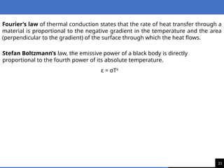
Fourier’s law ofthermal conduction states that the rate of heat transfer through a
material is proportional to the negative gradient in the temperature and the area
(perpendicular to the gradient) of the surface through which the heat flows.
Stefan Boltzmann’s law, the emissive power of a black body is directly
proportional to the fourth power of its absolute temperature.
ε = σT4
25
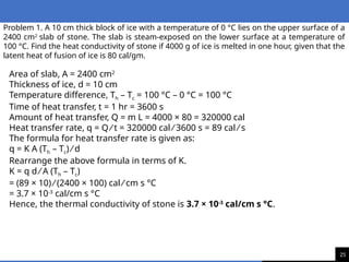
Problem 1. A10 cm thick block of ice with a temperature of 0 °C lies on the upper surface of a
2400 cm2
slab of stone. The slab is steam-exposed on the lower surface at a temperature of
100 °C. Find the heat conductivity of stone if 4000 g of ice is melted in one hour, given that the
latent heat of fusion of ice is 80 cal/gm.
Area of slab, A = 2400 cm2
Thickness of ice, d = 10 cm
Temperature difference, Th – Tc = 100 °C – 0 °C = 100 °C
Time of heat transfer, t = 1 hr = 3600 s
Amount of heat transfer, Q = m L = 4000 × 80 = 320000 cal
Heat transfer rate, q = Q ⁄ t = 320000 cal ⁄ 3600 s = 89 cal ⁄ s
The formula for heat transfer rate is given as:
q = K A (Th – Tc) ⁄ d
Rearrange the above formula in terms of K.
K = q d ⁄ A (Th – Tc)
= (89 × 10) ⁄ (2400 × 100) cal ⁄ cm s °C
= 3.7 × 10⁻³
cal/cm s °C
Hence, the thermal conductivity of stone is 3.7 × 10⁻³
cal/cm s °C.
26.
26
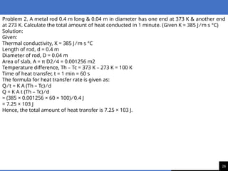
Problem 2. Ametal rod 0.4 m long & 0.04 m in diameter has one end at 373 K & another end
at 273 K. Calculate the total amount of heat conducted in 1 minute. (Given K = 385 J ⁄ m s °C)
Solution:
Given:
Thermal conductivity, K = 385 J ⁄ m s °C
Length of rod, d = 0.4 m
Diameter of rod, D = 0.04 m
Area of slab, A = π D2 ⁄ 4 = 0.001256 m2
Temperature difference, Th – Tc = 373 K – 273 K = 100 K
Time of heat transfer, t = 1 min = 60 s
The formula for heat transfer rate is given as:
Q ⁄ t = K A (Th – Tc) ⁄ d
Q = K A t (Th – Tc) ⁄ d
= (385 × 0.001256 × 60 × 100) ⁄ 0.4 J
= 7.25 × 10³ J
Hence, the total amount of heat transfer is 7.25 × 10³ J.
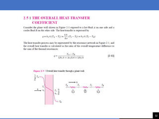
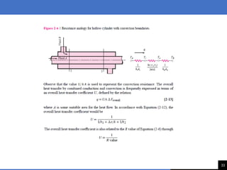
28
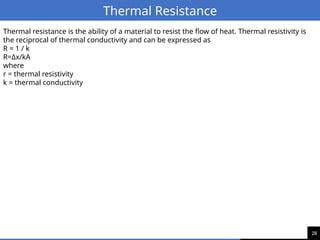
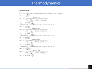
Thermal Resistance
Thermal resistanceis the ability of a material to resist the flow of heat. Thermal resistivity is
the reciprocal of thermal conductivity and can be expressed as
R = 1 / k
R=Δx/kA
where
r = thermal resistivity
k = thermal conductivity
34
•Heat and temperatureare not the same thing.
•Heat is the transfer of thermal energy between substances of different
temperatures.
• As thermal energy is added, the temperature of a substance increases.
•Temperature is a measure of the average kinetic energy of the molecules of a
substance.
• Increased temperature means greater average kinetic energy of the
molecules in the measured substance, and most substances expand when
heated.
• The absolute zero temperature (–273o
C/0
K) is the theoretical point at
which molecular motion stops.
•Atoms and molecules are perpetually in motion.
40
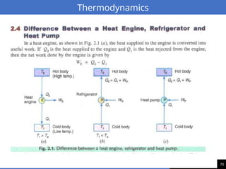
Thermodynamics
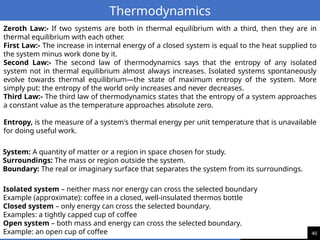
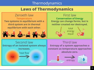
Zeroth Law:- Iftwo systems are both in thermal equilibrium with a third, then they are in
thermal equilibrium with each other.
First Law:- The increase in internal energy of a closed system is equal to the heat supplied to
the system minus work done by it.
Second Law:- The second law of thermodynamics says that the entropy of any isolated
system not in thermal equilibrium almost always increases. Isolated systems spontaneously
evolve towards thermal equilibrium—the state of maximum entropy of the system. More
simply put: the entropy of the world only increases and never decreases.
Third Law:- The third law of thermodynamics states that the entropy of a system approaches
a constant value as the temperature approaches absolute zero.
Entropy, is the measure of a system's thermal energy per unit temperature that is unavailable
for doing useful work.
System: A quantity of matter or a region in space chosen for study.
Surroundings: The mass or region outside the system.
Boundary: The real or imaginary surface that separates the system from its surroundings.
Isolated system – neither mass nor energy can cross the selected boundary
Example (approximate): coffee in a closed, well-insulated thermos bottle
Closed system – only energy can cross the selected boundary.
Examples: a tightly capped cup of coffee
Open system – both mass and energy can cross the selected boundary.
Example: an open cup of coffee
42
Thermodynamics
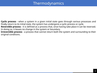
Cyclic process -when a system in a given initial state goes through various processes and
finally return to its initial state, the system has undergone a cyclic process or cycle.
Reversible process - it is defined as a process that, once having take place it can be reversed.
In doing so, it leaves no change in the system or boundary.
Irreversible process - a process that cannot return both the system and surrounding to their
original conditions.
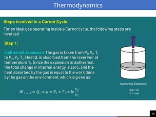
43.
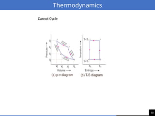
43
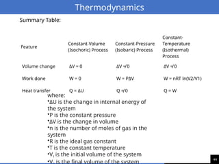
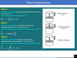
Thermodynamics
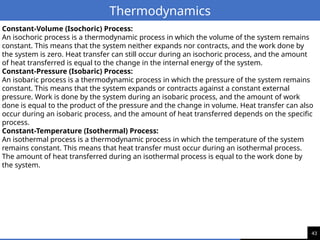
Constant-Volume (Isochoric) Process:
Anisochoric process is a thermodynamic process in which the volume of the system remains
constant. This means that the system neither expands nor contracts, and the work done by
the system is zero. Heat transfer can still occur during an isochoric process, and the amount
of heat transferred is equal to the change in the internal energy of the system.
Constant-Pressure (Isobaric) Process:
An isobaric process is a thermodynamic process in which the pressure of the system remains
constant. This means that the system expands or contracts against a constant external
pressure. Work is done by the system during an isobaric process, and the amount of work
done is equal to the product of the pressure and the change in volume. Heat transfer can also
occur during an isobaric process, and the amount of heat transferred depends on the specific
process.
Constant-Temperature (Isothermal) Process:
An isothermal process is a thermodynamic process in which the temperature of the system
remains constant. This means that heat transfer must occur during an isothermal process.
The amount of heat transferred during an isothermal process is equal to the work done by
the system.
52
Thermodynamics
Enthalpy A thermodynamicquantity equivalent to the total heat content of a
system is called enthalpy. Denoted by ‘H’.
Enthalpy change( )
∆𝐻 1. Exothermic and 2. Endothermic reactions Most chemical
reactions are accompanied by energy changes. Some absorb energy, while some
release it.
Exothermic reaction: An exothermic reaction is a reaction that releases energy to
the surroundings. Therefore the product contains less energy with respect to the
reactants. The energy is released as heat energy, so the surroundings warm.
Endothermic reaction: An endothermic reaction is a reaction that absorbs energy
from the surroundings. Therefore the products contain more energy with respect
to the reactants. The energy is absorbed as heat energy, so the surroundings cool
down.
Internal Energy is the sum of the molecular kinetic energy (due to random motion
of the molecules), the molecular potential energy (due to forces that act between
the atoms of molecules and between molecules.), and other kinds of molecular
energy.
56
Thermodynamics
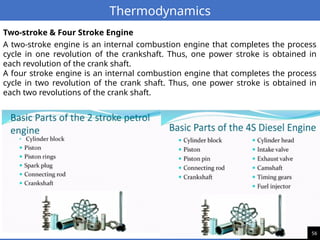
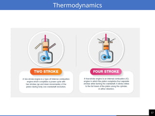
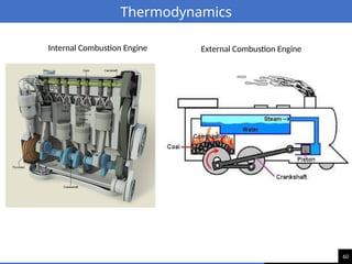
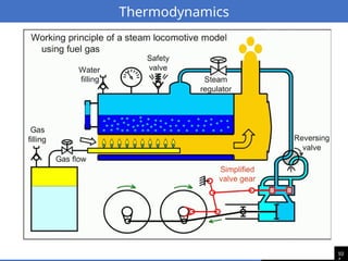
A two-stroke engineis an internal combustion engine that completes the process
cycle in one revolution of the crankshaft. Thus, one power stroke is obtained in
each revolution of the crank shaft.
A four stroke engine is an internal combustion engine that completes the process
cycle in two revolution of the crank shaft. Thus, one power stroke is obtained in
each two revolutions of the crank shaft.
Two-stroke & Four Stroke Engine
58
Thermodynamics
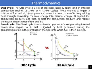
Otto cycle: TheOtto cycle is a set of processes used by spark ignition internal
combustion engines (2-stroke or 4- stroke cycles). These engines a) ingest a
mixture of fuel and air, b) compress it, c) cause it to react, thus effectively adding
heat through converting chemical energy into thermal energy, d) expand the
combustion products, and then e) eject the combustion products and replace
them with a new charge of fuel and air.
Diesel cycle: The Diesel cycle is a combustion process of a reciprocating internal
combustion engine. In it, fuel is ignited by heat generated during the
compression of air in the combustion chamber, into which fuel is then injected.
63
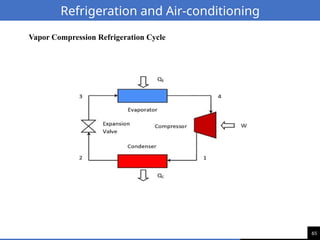
Refrigeration and Air-conditioning
Airconditioning is a type of refrigeration system that is used to cool and
dehumidify air. It is typically used in buildings and other enclosed spaces. Air
conditioning systems typically use a refrigerant and a compressor to remove heat
from the air. The cooled air is then circulated through the building to provide a
comfortable environment.
64.
64
Refrigeration and Air-conditioning
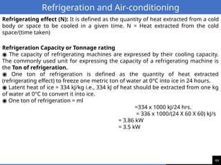
Refrigeratingeffect (N): It is defined as the quantity of heat extracted from a cold
body or space to be cooled in a given time. N = Heat extracted from the cold
space/(time taken)
Refrigeration Capacity or Tonnage rating
◉ The capacity of refrigerating machines are expressed by their cooling capacity.
The commonly used unit for expressing the capacity of a refrigerating machine is
the Ton of refrigeration.
◉ One ton of refrigeration is defined as the quantity of heat extracted
(refrigerating effect) to freeze one metric ton of water at 0°C into ice in 24 hours.
◉ Latent heat of ice = 334 kJ/kg i.e., 334 kJ of heat should be extracted from one kg
of water at 0°C to convert it into ice.
◉ One ton of refrigeration = ml
=334 x 1000 kJ/24 hrs.
= 336 x 1000/(24 X 60 X 60) kJ/s
= 3.86 kW
= 3.5 kW
68
Thermodynamics
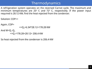
A refrigeration systemoperates on the reversed Carnot cycle. The maximum and
minimum temperatures are 250
C and 720
C, respectively. If the power input
required is 28.12 KW, find the heat rejected from the condenser.
Solution: COP==
Again, COP=
=>Q2=6.34*28.12=178.28 KW
And W=Q1-Q2
=>Q1=178.28+28.12= 206.4 KW
So heat rejected from the condenser is 206.4 KW
69.
69
Thermodynamics
Find the COPof a refrigeration system if the work input is 80 kJ/kg and the
refrigeration effect produced is 160 kJ/kg of refrigerant flowing.
71
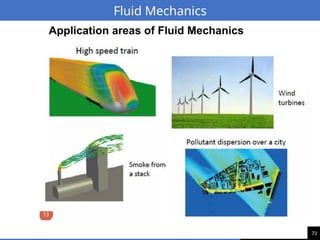
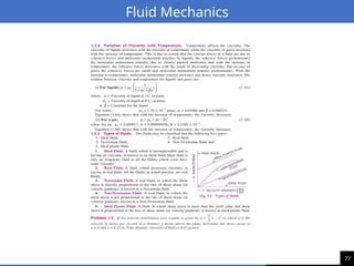
Fluid Mechanics
Application areasof Fluid Mechanics
Mechanics of fluids is extremely important in many areas of engineering and science.
Examples are:
Biomechanics
• Blood flow through arteries and veins
• Airflow in the lungs
• Flow of cerebral fluid
Households
• Piping systems for cold water, natural gas, and sewage
• Piping and ducting network of heating and air- conditioning systems
• refrigerator, vacuum cleaner, dish washer, washing machine, water meter, natural gas
meter, air conditioner, radiator, etc.
Meteorology and Ocean Engineering
• Movements of air currents and water currents
Mechanical Engineering
• Design of pumps, turbines, air-conditioning equipment, pollution-control equipment, etc.
• Design and analysis of aircraft, boats, submarines, rockets, jet engines, wind turbines,
biomedical devices, the cooling of electronic components, and the transportation of water,
crude oil, and natural gas.
Civil Engineering
• Transport of river sediments
• Pollution of air and water
• Design of piping systems
• Flood control systems
Chemical Engineering
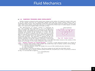
72.
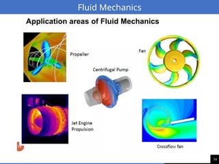
72
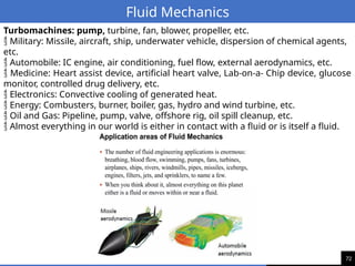
Fluid Mechanics
Turbomachines: pump,turbine, fan, blower, propeller, etc.
Military: Missile, aircraft, ship, underwater vehicle, dispersion of chemical agents,
etc.
Automobile: IC engine, air conditioning, fuel flow, external aerodynamics, etc.
Medicine: Heart assist device, artificial heart valve, Lab-on-a- Chip device, glucose
monitor, controlled drug delivery, etc.
Electronics: Convective cooling of generated heat.
Energy: Combusters, burner, boiler, gas, hydro and wind turbine, etc.
Oil and Gas: Pipeline, pump, valve, offshore rig, oil spill cleanup, etc.
Almost everything in our world is either in contact with a fluid or is itself a fluid.
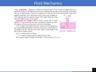
95
Fluid Mechanics
Angular Velocity:
Angularvelocity, also known as rotational velocity, describes the rate of rotation
of a body about an axis. It is typically denoted by the Greek letter omega (ω) and
is measured in radians per second (rad/s). Angular velocity can be calculated as
the change in angle (θ) divided by the change in time (t):
ω = (θ/t)
Vorticity:
Vorticity is a measure of the local rotation of a fluid. It is a vector quantity defined
as the curl of the fluid velocity vector, which represents the local rotation of the
fluid particles. Vorticity can be calculated using the formula:
ω = × v
∇
where:
ω is the vorticity vector
∇ is the del operator
v is the fluid velocity vector
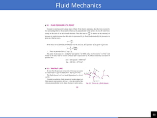
96.
96
Fluid Mechanics
Compressible Flow:
Compressibleflow is a fluid flow in which the density of the fluid can change significantly with
pressure. This is typically the case for gases, which can undergo large changes in density due
to their relatively low intermolecular forces. Compressible flow is often encountered in high-
speed flows, such as those encountered in aircraft or gas turbines.
Incompressible Flow:
Incompressible flow is a fluid flow in which the density of the fluid remains approximately
constant. This is typically the case for liquids, which have much stronger intermolecular forces
and are less prone to density changes. Incompressible flow is often encountered in low-speed
flows, such as those encountered in rivers, pipes, and open channels.
Viscous Flow:
Viscous flow is a fluid flow in which the fluid particles experience resistance to their movement
due to friction between the particles. This friction is caused by the interaction between the
fluid molecules and is known as viscosity. Viscous flow is typically encountered in fluids with
high molecular weights, such as oils and syrups.
Inviscid flow is a theoretical concept of fluid flow where viscosity is assumed to be zero.
97.
97
Fluid Mechanics
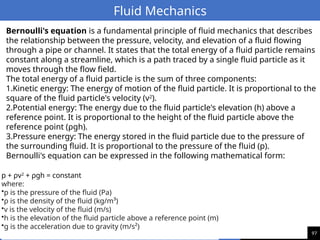
p +ρv2
+ ρgh = constant
where:
•p is the pressure of the fluid (Pa)
•ρ is the density of the fluid (kg/m³)
•v is the velocity of the fluid (m/s)
•h is the elevation of the fluid particle above a reference point (m)
•g is the acceleration due to gravity (m/s²)
Bernoulli's equation is a fundamental principle of fluid mechanics that describes
the relationship between the pressure, velocity, and elevation of a fluid flowing
through a pipe or channel. It states that the total energy of a fluid particle remains
constant along a streamline, which is a path traced by a single fluid particle as it
moves through the flow field.
The total energy of a fluid particle is the sum of three components:
1.Kinetic energy: The energy of motion of the fluid particle. It is proportional to the
square of the fluid particle's velocity (v2
).
2.Potential energy: The energy due to the fluid particle's elevation (h) above a
reference point. It is proportional to the height of the fluid particle above the
reference point (ρgh).
3.Pressure energy: The energy stored in the fluid particle due to the pressure of
the surrounding fluid. It is proportional to the pressure of the fluid (p).
Bernoulli's equation can be expressed in the following mathematical form:
98.
98
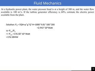
Fluid Mechanics
At ahydraulic power plant, the water pressure head is at a height of 300 m, and the water flow
available is 100 m3
/s. If the turbine generator efficiency is 60%, estimate the electric power
available from the plant.
Solution: Pin= ϒQH=ρ*g*Q*H=1000*9.81*100*300
=2.943*108
Watt
η= Pout/Pin
=> Pout =176.58*106
Watt
=176.58MW
99.
99
Fluid Mechanics
Fluid dynamics
Fluiddynamics is a branch of physics that deals with the study of fluids in motion. It
encompasses a wide range of topics, from the microscopic behavior of individual
molecules to the macroscopic behavior of large-scale fluid systems.
Fluid Kinematics
Fluid kinematics is a branch of fluid mechanics that deals with the motion of fluids
without considering the forces that cause the motion. It is concerned with the
description and analysis of the motion of fluid particles and the properties of fluid
flow fields.
Applications of Fluid Kinematics
Fluid kinematics has a wide range of applications in various fields, including:
•Aerodynamics: The study of air flow around objects, such as airplanes and wind
turbines.
•Hydrodynamics: The study of water flow, such as in rivers, oceans, and ships.
•Meteorology: The study of atmospheric motion, such as weather systems and
climate change.
•Engineering: The design of fluid machinery, such as pumps, turbines, and
compressors.
Understanding fluid kinematics is essential for designing and analyzing fluid
systems and for predicting the behavior of fluids in various applications.airflow
100.
10
Fluid Mechanics
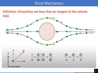
Streamlines
A streamlineis a line tangent to the velocity vector of a fluid particle at any given
instant. It represents the instantaneous path of a fluid particle. Streamlines are
always continuous and non-intersecting. They provide a visual representation of
the direction of fluid flow at any point in the flow field.
Pathlines
A pathline is the trajectory of a single fluid particle over time. It represents the
actual path that a fluid particle takes as it moves through the flow field. Unlike
streamlines, pathlines are not necessarily continuous or non-intersecting.
Streaklines
A streakline is the locus of all the fluid particles that have passed through a
particular spatial point in the past. It is formed by injecting a dye or tracer into the
fluid at a fixed point and observing the streak of dye or tracer as it is carried away
by the flow. Streaklines are always continuous but may intersect.
10
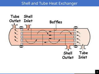
Fluid Mechanics
Heat RecoverySystem
A heat recovery system (HRS) is a device or system that captures waste heat from a
process or source and transfers it to another process or use. HRSs are used to
improve energy efficiency and reduce environmental impact.
Types of Heat Recovery Systems:
There are many different types of HRSs, including:
Air-to-air heat exchangers: These HRSs transfer heat between two airstreams. They
are commonly used in HVAC systems to recover heat from exhaust air.
Liquid-to-liquid heat exchangers: These HRSs transfer heat between two liquid
streams. They are commonly used in industrial processes to recover heat from
waste water or exhaust gases.
Heat pipes: These HRSs use a working fluid to transfer heat from one location to
another. They are commonly used in high-temperature applications.
Benefits of Heat Recovery Systems:
There are many benefits to using HRSs, including:
Reduced energy consumption: HRSs can help to reduce energy consumption by
capturing and reusing waste heat.
Lower emissions: HRSs can help to reduce emissions by reducing the need for fossil
fuels.
Improved financial performance: HRSs can improve financial performance by
reducing energy costs.
103.
10
Fluid Mechanics
Thermal EnergyStorage (TES)
Thermal energy storage (TES) is the process of storing thermal energy for later use. TES can be
used to store heat or cold.
Types of Thermal Energy Storage:
There are many different types of TES, including:
Sensible heat storage: This type of TES stores heat in the form of a temperature
change. Water, rocks, and concrete are common sensible heat storage materials.
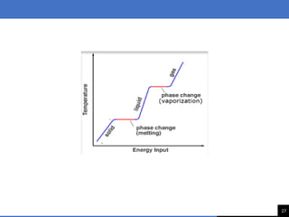
Latent heat storage: This type of TES stores heat in the form of a change in phase, such as
melting or freezing. Phase change materials (PCMs) are common latent heat storage materials.
Thermochemical storage: This type of TES stores heat in the form of a chemical
reaction. Reversible chemical reactions are used to store and release heat.
Benefits of Thermal Energy Storage:
There are many benefits to using TES, including:
Load leveling: TES can be used to level out the load on power plants and other energy sources.
Peak shaving: TES can be used to reduce peak energy demand.
Renewable energy integration: TES can be used to integrate renewable energy sources, such as
solar and wind power, into the grid.
10
Thermodynamics
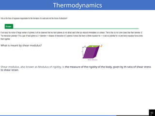
What is meantby shear modulus?
Shear modulus, also known as Modulus of rigidity, is the measure of the rigidity of the body, given by th ratio of shear stress
to shear strain.
106.
10
Fluid Mechanics
Compressible Flow:
Compressibleflow is a fluid flow in which the density of the fluid can change significantly with
pressure. This is typically the case for gases, which can undergo large changes in density due
to their relatively low intermolecular forces. Compressible flow is often encountered in high-
speed flows, such as those encountered in aircraft or gas turbines.
Incompressible Flow:
Incompressible flow is a fluid flow in which the density of the fluid remains approximately
constant. This is typically the case for liquids, which have much stronger intermolecular forces
and are less prone to density changes. Incompressible flow is often encountered in low-speed
flows, such as those encountered in rivers, pipes, and open channels.
Viscous Flow:
Viscous flow is a fluid flow in which the fluid particles experience resistance to their movement
due to friction between the particles. This friction is caused by the interaction between the
fluid molecules and is known as viscosity. Viscous flow is typically encountered in fluids with
high molecular weights, such as oils and syrups.
Inviscid flow is a theoretical concept of fluid flow where viscosity is assumed to be zero.
107.
10
Refrigeration and Air-conditioning
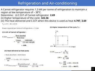
ACarnot refrigerator requires 1.3 kW per tonne of refrigeration to maintain a
region at low temperature of – 38°C.
Determine : (i) C.O.P. of Carnot refrigerator 2.69
(ii) Higher temperature of the cycle 322.36
(iii) The heat delivered and C.O.P. when this device is used as heat 4.797, 3.69
10
Thermodynamics
A steel wireof length 4.7 m and cross-sectional area 3.0×10 5m2
− stretches by the same
amount as a copper wire of length 3.5 m and cross-sectional area of 4.0×10 5m2
− under
a given load. What is the ratio of the Youngs modulus of steel to that of copper ?