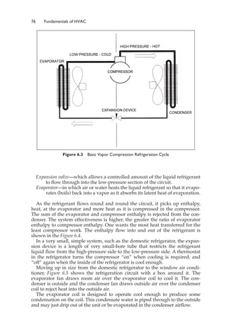
This document provides an introduction to fundamentals of HVAC systems. It discusses the brief history of HVAC, from early uses of fire for heating to modern air conditioning. The document defines HVAC and describes the seven major air conditioning processes: heating, cooling, humidifying, dehumidifying, cleaning, circulating, and ventilating. It introduces the concept of controlling temperature, humidity, ventilation, filtration and air movement to achieve thermal comfort for building occupants.


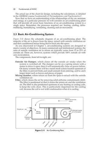
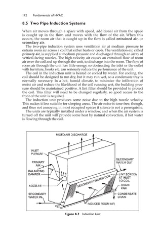
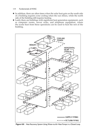
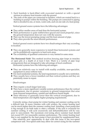
![34 Fundamentals of HVAC
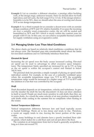
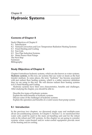
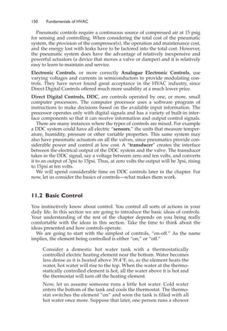
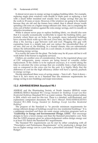
To predict thermal comfort we must have an idea of the clothing that will be worn
by the occupants.
Due to the large variety of materials, weights, and weave of fabrics, clothing
estimates are just rough estimates. Each article has an insulating value, unit “clo.”
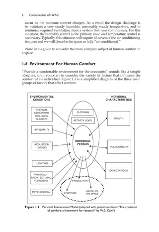
For example: a long-sleeved sweat shirt is 0.34 clo, straight trousers (thin)
are 0.15 clo, light underwear is 0.04 clo, ankle-length athletic socks are 0.02 clo,
and sandals are 0.02 clo. These clo values can be added to give an overall
clothing insulation value. In this case, the preceding set of clothes has an over-
all clothing insulation value of 0.57 clo.
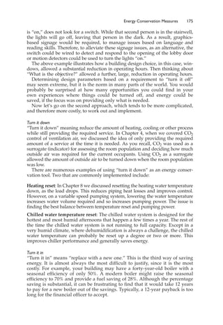
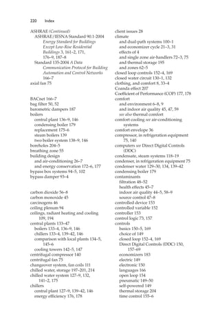
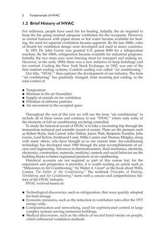
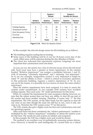
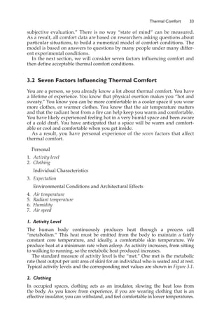
Typical values for clothing ensembles are shown in Figure 3.2. All include
shoes, socks, and light underwear.
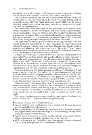
Later in this Chapter we will introduce a chart, Figure 3.4, that illustrates
comfortable conditions with 0.5 clo and 1.0 clo. As you can see from Figure 3.2,
0.5 clo is very light clothing, and 1.0 clo is heavy indoor clothing.
3. Occupants’ Expectations
People’s expectations affect their perception of comfort in a building. Consider
the following three scenarios that all occur on a very hot day:
䊉 A person walks into an air-conditioned office building. The person expects
the building to be thermally comfortable.
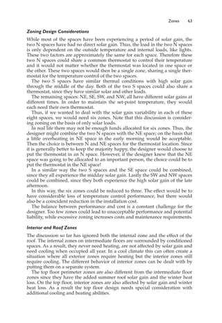
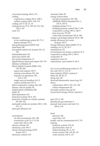
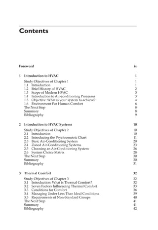
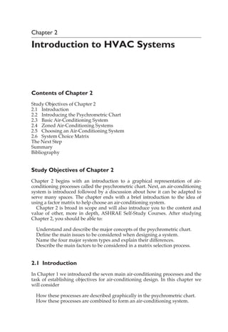
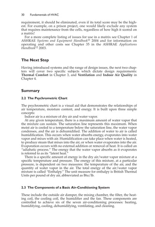
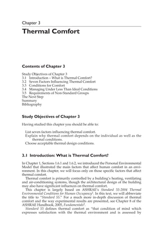
Activity met*
Sleeping 0.7
Reading or writing, seated in office 1.0
Filing, standing in office 1.4
Walking about in office 1.7
Walking 2 mph 2.0
Housecleaning 2.0 to 3.4
Dancing, social 2.4 to 4.4
Heavy machine work 4.0
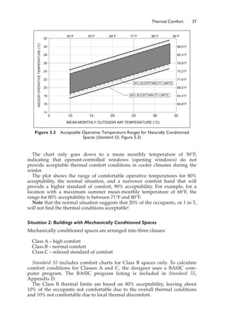
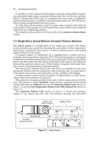
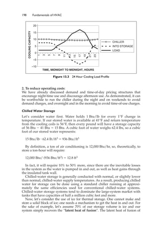
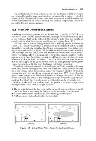
Figure 3.1 Typical Metabolic Heat Generation for Various Activities (Standard 55,
Normative Appendix A, Extracted data) [*1 met ⫽ 18.4 Btu/h ⭈ ft2]
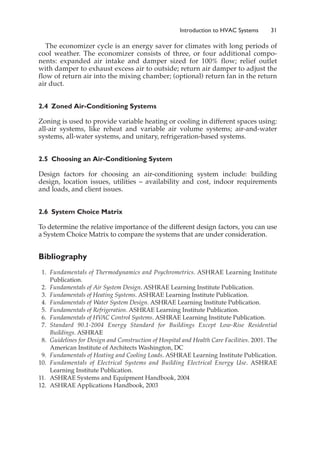
Ensemble Description clo*
Trouser, short sleeve shirt 0.57
Knee-length skirt, short-sleeve shirt (sandals) 0.54
Trousers, long-sleeved shirt, suit jacket 0.96
Knee-length skirt, long-sleeved shirt, half slip,
panty hose, long-sleeved sweater 1.10
Long-sleeved coveralls, T-shirt 0.72
Figure 3.2 Typical Insulation Values for Clothing Ensembles (Standard 55, Appendix B,
Table B-1, extracted data) [*1 clo ⫽ 0.88°F ⭈ ft2 ⭈ h/Btu]](https://image.slidesharecdn.com/fundahvacsystem-230310075742-d53448e6/85/Funda_HVAC_system-pdf-45-320.jpg)