Download as PDF, PPTX


![Building Air Distribution 2.5
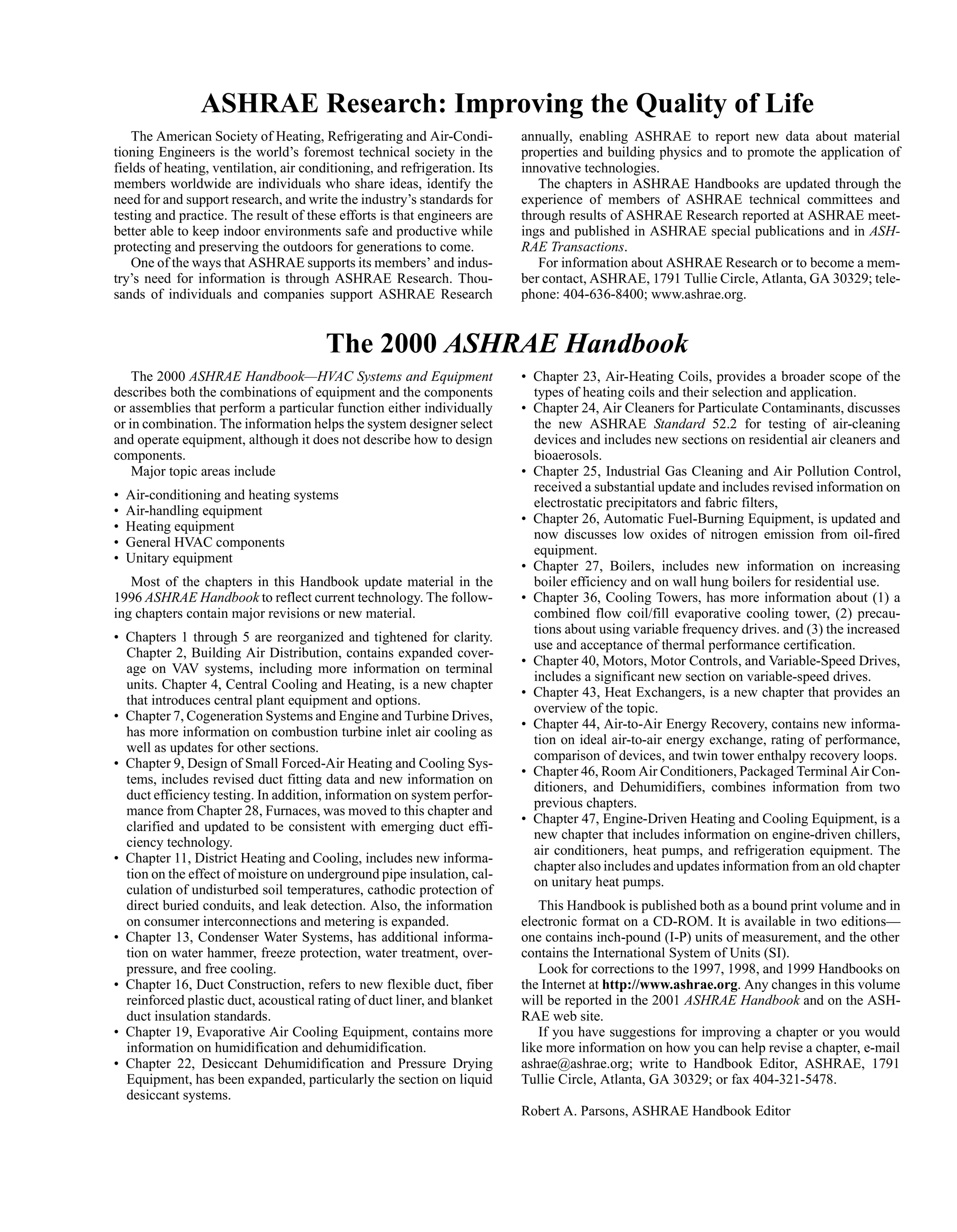
supersaturated system is a variation on direct spray. In this sys-
tem, tiny droplets of free moisture are carried by the air into the
conditioned space where they evaporate, providing additional
cooling. This reduces the amount of air needed for a given space
load (Figure 4).
• Indirect evaporative cooling adiabatically cools outdoor air or
exhaust air from the conditioned space by spraying water, then
passes that cooled air through one side of a heat exchanger, while
the air to be supplied to the space is cooled by passing through the
other side of the heat exchanger. Chapter 19 has further informa-
tion on this method of cooling.
Chapter 6 of the 1997 ASHRAE Handbook—Fundamentals
detail the psychrometric process of these methods.
Heating
The basic methods used for heating include
• Steam, which uses the latent heat of the fluid
• Fluid-filled coils, which use temperature differences between the
warm fluid and the cooler air
• Electric heating, which also uses the temperature difference
between the heating coil and the air to exchange energy
The effect on the airstream for each of these processes is the
same and is shown in Figure 5. For basic equations, refer to Chapter
6 of the 1997 ASHRAE Handbook—Fundamentals.
Humidification
The methods used to humidify air include
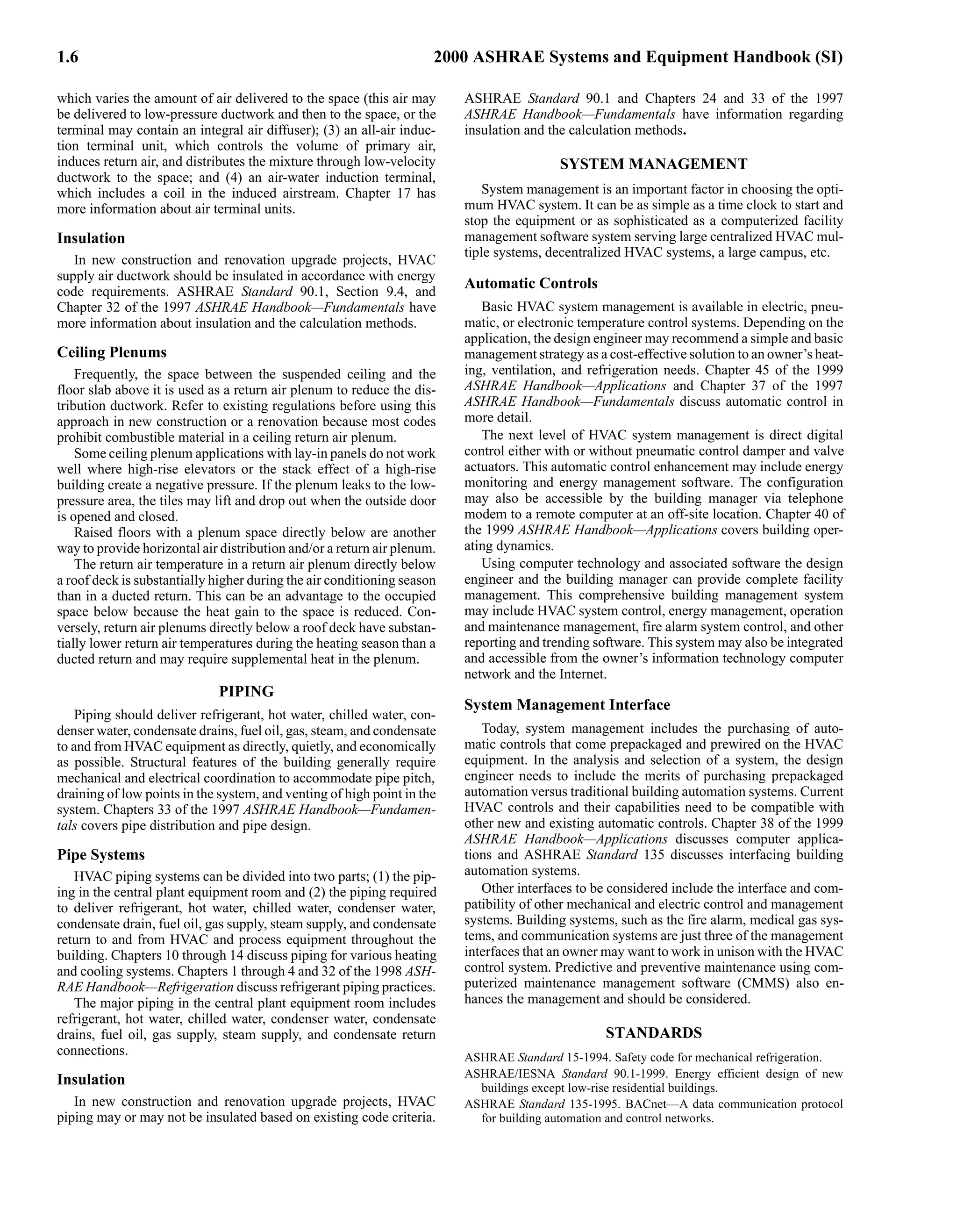
• Direct spray of recirculated water into the airstream (air
washer) reduces the dry-bulb temperature while maintaining an
almost constant wet bulb in an adiabatic process [see Figure 3,
Paths (1) to (3)]. The air may also be cooled and dehumidified, or
heated and humidified by changing the temperature of the spray.
In one variation, the surface area of water exposed to the air is
increased by spraying water onto a cooling/heating coil. The coil
surface temperature determines the leaving air conditions.
Another method is to spray or distribute water over a porous
medium, such as those in evaporative coolers and commercial
greenhouses. This method requires careful monitoring of the
water condition to keep biological contaminants from the air-
stream (Figure 6).
• Compressed air that forces water through a nozzle into the air-
stream is essentially a constant wet-bulb (adiabatic) process. The
water must be treated to keep particulates from entering the air-
stream and contaminating or coating equipment and furnishings.
Many types of nozzles are available.
• Steam injection, which is a constant dry-bulb process (Figure 7).
However, as the steam injected becomes superheated, the leaving
dry-bulb temperature increases. If live steam is injected into the
airstream, the boiler water treatment chemical must be nontoxic
to the occupants and, if the air is supplying a laboratory, to the
research under way.
Dehumidification
Moisture condenses on a cooling coil when its surface tempera-
ture is below the dew point of the air, thus reducing the humidity of
the air. In a similar manner, air will also be dehumidified if a fluid
with a temperature below the airstream dew point is sprayed into the
Fig. 4 Water Spray Humidifier
Fig. 5 Steam, Hot Water, and Electric Heating
Fig. 6 Humidification](https://image.slidesharecdn.com/ashrae2000heatingventilationairconditioningequipmenthandbook-221028112511-3dff6ef4/75/Ashrae-2000-Heating-Ventilation-Air-Conditioning-Equipment-Handbook-pdf-13-2048.jpg)
![2.8 2000 ASHRAE Systems and Equipment Handbook (SI)
temperature above 2 to 7°C; preferably, it should become inopera-
tive at outdoor temperatures of 7°C. Inner distributing tube or inte-
gral face and bypass coils are preferable with steam. Hot water
preheat coils should have a constant flow recirculating pump and
should be piped for parallel flow so that the coldest air will contact
the warmest part of the coil surface first. Chapter 23 provides more
detailed information on heating coils.
Cooling Coil
In this section, sensible and latent heat are removed from the air.
In all finned coils, some air passes through without contacting the
fins or tubes. The amount of this bypass can vary from 30% for a
four-row coil at 3.5 m/s to less than 2% for an eight-row coil at 1.5
m/s. The dew point of the air mixture leaving a four-row coil might
satisfy a comfort installation with 25% or less outdoor air, a small
internal latent load, and sensible temperature control only. For close
control of room conditions for precision work, a deeper coil may be
required. Chapter 21 provides more information on cooling coils
and their selection.
Coil freezing can be a serious problem with chilled water coils.
Full flow circulation of chilled water during freezing weather, or
even reduced flow with a small recirculating pump, minimizes coil
freezing and eliminates stratification. Further, continuous full flow
circulation can provide a source of off-season chilled water in air-
and-water systems. Antifreeze solutions or complete coil draining
also prevent coil freezing. However, because it is difficult, if not
impossible, to drain most cooling coils completely, caution should
be exercised if this option is considered.
Reheat Coil
Reheat systems are strongly discouraged, unless recovered
energy is used (see ASHRAE Standard 90.1). Reheating is limited
to laboratory, health care, or similar applications where temperature
and relative humidity must be controlled accurately. Heating coils
located in the reheat position, as shown in Figure 1, are frequently
used for warm-up, although a coil in the preheat position is prefer-
able. Hot water heating coils provide the highest degree of control.
Oversized coils, particularly steam, can stratify the airflow; thus,
where cost-effective, inner distributing coils are preferable for
steam applications. Electric coils may also be used. Chapter 23 has
more information.
Humidifiers
Humidifiers may be installed as part of the central station air-
handling unit, or in terminals at the point of use, or both. Where
close humidity control of selected spaces is required, the entire sup-
ply airstream may be humidified to a lower humidity level in the air
handler, with terminal humidifiers located in the supply ducts serv-
ing just those selected spaces bringing them up to their required
humidity levels. For comfort installations not requiring close con-
trol, moisture can be added to the air by mechanical atomizers or
point-of-use electric or ultrasonic humidifiers. Proper location of
this equipment prevents stratification of moist air in the system.
In this application, the heat of evaporation should be replaced by
heating the recirculated water, rather than by increasing the size of
the preheat coil. Steam grid humidifiers with dew-point control usu-
ally are used for accurate humidity control. It is not possible to add
moisture to saturated air, even with a steam grid humidifier. Air in
a laboratory or other application that requires close humidity control
must be reheated after leaving a cooling coil before moisture can be
added. The capacity of the humidifying equipment should not
exceed the expected peak load by more than 10%. If the humidity is
controlled from the room or the return air, a limiting humidistat and
fan interlock may be needed in the supply duct. This prevents con-
densation and mold or mildew growth in the ductwork when tem-
perature controls call for cooler air. Humidifiers add some sensible
heat that should be accounted for in the psychrometric evaluation.
Chapter 20 has additional information.
Dehumidifiers
Many dehumidification systems are available. Dust can be a
problem with solid desiccants, and lithium contamination is a con-
cern with spray equipment. Chapter 21 discusses dehumidification
by cooling coils and Chapter 22 discusses desiccant dehumidifiers.
Odor Control
Most devices control odors and other contaminants with acti-
vated carbon or potassium permanganate as a basic filter medium.
Other systems use electronic control methods. Chapters 12 and 13
of the 1997 ASHRAE Handbook—Fundamentals have more infor-
mation on odor control.
Supply Air Fan
Either axial flow, centrifugal, or plug fans may be chosen as sup-
ply air fans for straight-through flow applications. In factory-fabri-
cated units, more than one centrifugal fan may be tied to the same
shaft. If headroom permits, a single-inlet fan should be chosen when
air enters at right angles to the flow of air through the equipment.
This permits a direct flow of air from the fan wheel into the supply
duct without abrupt change in direction and loss in efficiency. It also
permits a more gradual transition from the fan to the duct and
increases the static regain in the velocity pressure conversion. To
minimize inlet losses, the distance between the casing walls and the
fan inlet should be at least the diameter of the fan wheel. With a sin-
gle-inlet fan, the length of the transition section should be at least
half the width or height of the casing, whichever is longer. If fans
blow through the equipment, the air distribution through the down-
stream components needs analyzing, and baffles should be used to
ensure uniform air distribution. Chapter 18 has more information.
AIR-HANDLING UNIT CONCERNS
Outside Air Requirements
A common complaint regarding buildings is the lack of outside
air. This problem is especially a concern in VAV systems where out-
side air quantities are established for peak loads and are then
reduced in proportion to the air supplied during periods of reduced
load. A simple control added to the outside air damper can eliminate
this problem and keep the amount of outside air constant, regardless
of the operation of the VAV system. However, the need to preheat
the outside air must be considered if this control is added.
Another problem is that some codes require as little as 2.4 L/s per
person [about 0.25 L/(s·m2)] of outside air. This amount is far too
low for a building in which modern construction materials are used.
Higher outside air quantities may be required to reduce odors,
VOC’s, and potentially dangerous pollutants. ASHRAE Standard
62 provides information on ventilation for acceptable indoor air
quality. Air quality (i.e., the control or reduction of contaminants
such as volatile organic compounds, formaldehyde from furnish-
ings, and dust) must be reviewed by the engineer.
Heat recovery devices are becoming more popular as the
requirements for outside air increase. They are used extensively in
research and development facilities and in hospitals and laborato-
ries where HVAC systems supply 100% outside air. Many types are
available, and the type of facility usually determines which is most
suitable. Many countries with extreme climates provide heat
exchangers on outside/relief air, even for private homes. This trend
is now appearing in larger commercial buildings worldwide. Heat
recovery devices such as air-to-air plate heat exchangers can save
energy and reduce the required capacity of primary cooling and
heating plants by 20% and more under certain circumstances.](https://image.slidesharecdn.com/ashrae2000heatingventilationairconditioningequipmenthandbook-221028112511-3dff6ef4/75/Ashrae-2000-Heating-Ventilation-Air-Conditioning-Equipment-Handbook-pdf-16-2048.jpg)


![6.2 2000 ASHRAE Systems and Equipment Handbook (SI)
• The modular panel provides flexibility to meet changes in
partitioning.
• A 100% outdoor air system may be installed with smaller penalties
in terms of refrigeration load because of reduced air quantities.
• A common central air system can serve both the interior and
perimeter zones.
• Wet surface cooling coils are eliminated from the occupied space,
reducing the potential for septic contamination.
• The panel system can use the automatic sprinkler system piping
(see NFPA Standard 13, Chapter 3, Section 3.6). The maximum
water temperature must not fuse the heads.
• Radiant panel heating and cooling and minimum supply air quan-
tities provide a draft-free environment.
• Noise associated with fan-coil or induction units is eliminated.
• Peak loads are reduced as a result of thermal energy storage in the
panel structure, exposed walls, and partitions.
• Panels can be coupled with other conditioning systems for heat
loss (gain) compensation for cold or hot floors, windows, etc.
Disadvantages are similar to those listed in Chapter 3 of the
1997 ASHRAE Handbook—Fundamentals. In addition:
• Response time can be slow if controls and/or heating elements are
not selected or installed correctly
• Improper installation of pipe or element spacing and/or incorrect
sizing of heat source can cause nonuniform surface temperatures
or insufficient heating capacity
HEAT TRANSFER BY PANEL SURFACES
A heated or cooled panel transfers heat to or from a room by radi-
ation and natural convection.
Radiation Transfer
The basic equation for a multisurface enclosure with gray, dif-
fuse isothermal surfaces is derived by radiosity formulation meth-
ods (Chapter 3 of the 1997 ASHRAE Handbook—Fundamentals).
This equation may be written as
(1)
where
qr = net radiation heat transferred by panel surface, W/m2
Jp = total radiosity that leaves panel surface, W/m2
Jj = radiosity from another surface in room, W/m2
Fpj = radiation angle factor between panel surface and another surface
in room (dimensionless)
n = number of surfaces in room other than panel
Equation (1) can be applied to simple and complex enclosures
with varying surface temperatures and emittances. The net radiation
transferred by the panels can be found by determining unknown Jj
if the number of surfaces is small. More complex enclosures require
computer calculations.
Radiation angle factors can be evaluated using Figure 6 in Chap-
ter 3 of the 1997 ASHRAE Handbook—Fundamentals. Fanger
(1972) shows room-related angle factors; they may also be devel-
oped from algorithms in ASHRAE’s Energy Calculations 1 (1976).
Several methods have been developed to simplify Equation (1)
by reducing a multisurface enclosure to a two-surface approxima-
tion. In the MRT method, the radiant interchange in a room is mod-
eled by assuming that the surfaces radiate to a fictitious surface that
has an area emittance and temperature giving about the same heat
transfer as the real multisurface case (Walton 1980). In addition,
angle factors do not need to be determined in the evaluation of a two-
surface enclosure. The MRT equation may be written as
(2)
where
σ = Stefan-Boltzmann constant = 5.67 × 10⁻⁸ W/(m2·K4)
Fr = radiation exchange factor (dimensionless)
Tp = effective temperature of heated (cooled) panel surface, K
Tr = temperature of fictitious surface (unheated or uncooled), K
The temperature of the fictitious surface is given by an area emit-
tance weighted average of all surfaces other than the panel:
(3)
where
Aj = area of surfaces other than panel
εj = thermal emittance other than panel (dimensionless)
When the emittances of an enclosure are nearly equal, and sur-
faces exposed to the panel are marginally unheated (uncooled),
then Equation (3) becomes the area-weighted average temperature
(AUST) of unheated (uncooled) surfaces exposed to the panels.
The radiation interchange factor for two-surface radiation heat
exchange is given by the Hottel equation:
(4)
where
Fp−r = radiation angle factor from panel to fictitious surface
(1.0 for flat panel)
Ap, Ar = area of panel surface and fictitious surface, respectively
εp, εr = thermal emittance of panel surface and fictitious surface,
respectively (dimensionless)
In practice, the thermal emittance εp of nonmetallic or painted
metal nonreflecting surfaces is about 0.9. When this emittance is
used in Equation (4), the radiation exchange factor F
r is about 0.87
for most rooms. Substituting this value in Equation (2), σF
r
becomes about 5 × 10⁻⁸. Min et al. (1956) showed that this constant
was 5.03 × 10⁻⁸ in their test room. The radiation equation for heat-
ing or cooling becomes
(5)
where
tp = effective panel surface temperature, °C
AUST = area-weighted average temperature of uncontrolled surfaces
in room, °C
Equation (5) establishes the general sign convention for this
chapter, which states that heating by the panel is positive and cool-
ing by the panel is negative.
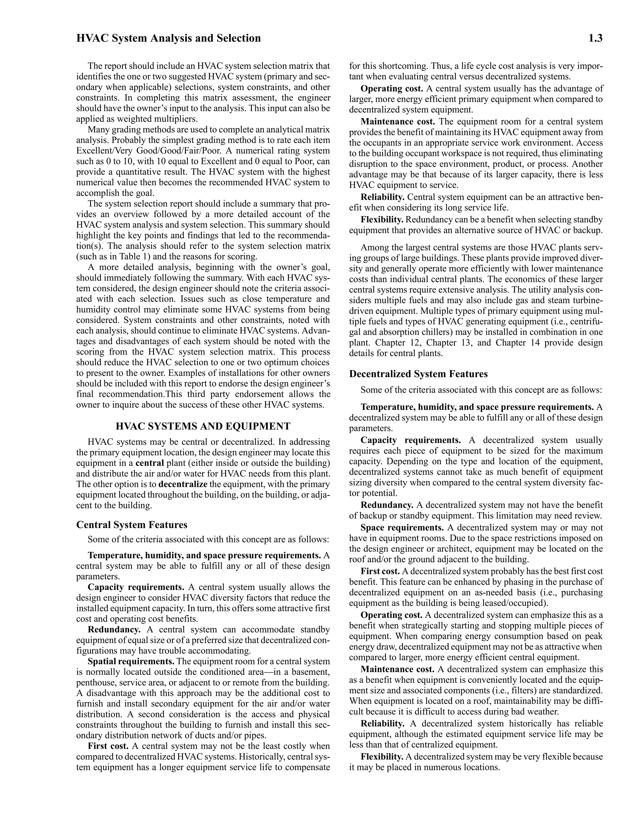
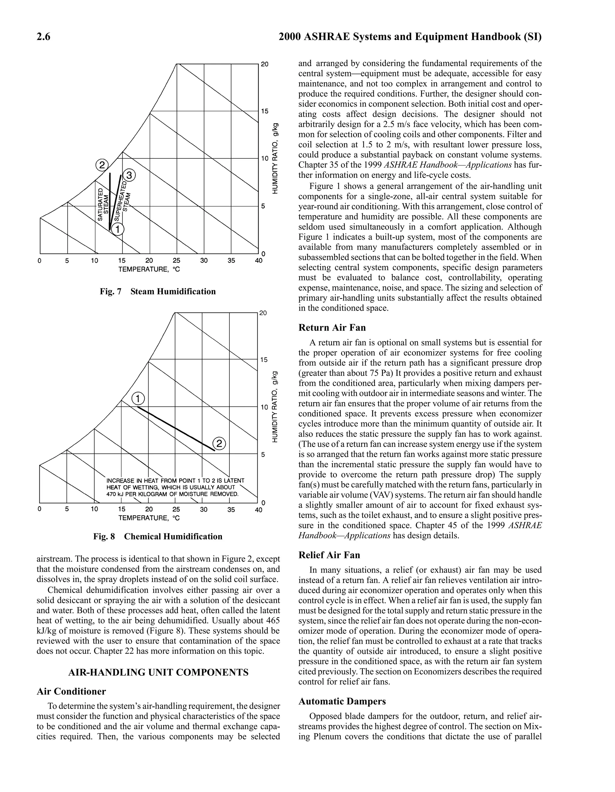
Radiation exchange calculated from Equation (5) is given in
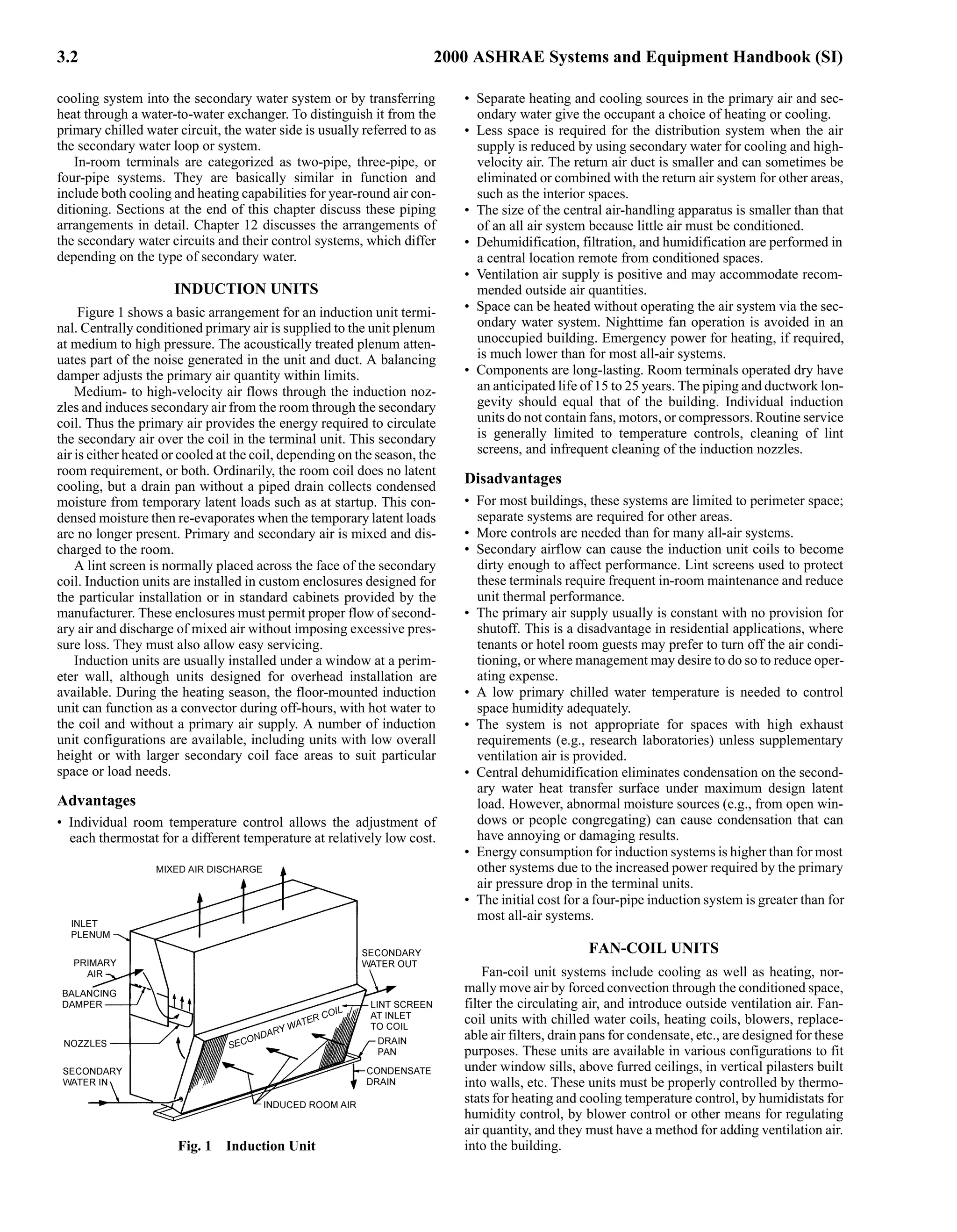
Figure 1. The values apply to ceiling, floor, or wall panel output.
Radiation removed by a cooling panel for a range of normally
encountered temperatures is given in Figure 2.
In many specific instances where normal multistory commercial
construction and fluorescent lighting are used, the room tempera-
ture at the 1.5 m level closely approaches the average uncooled sur-
face temperature (AUST). In structures where the main heat gain is
through the walls or where incandescent lighting is used, the wall
qr Jp Fpj Jj
j=1
n
∑
–
=
qr σF
r Tp
4 Tr
4
–
[ ]
=
Tr
AjεjTj
j p
≠
n
∑
Ajεj
j p
≠
n
∑
-----------------------
-
=
Fr
1
1
Fp r
–
-----------
-
1
εp
----
- 1
–
Ap
Ar
-----
-
1
εr
---
- 1
–
+ +
-----------------------------------------------------------------------
=
qr 5 10
8
–
tp 273
+
( )
4
AUST 273
+
( )
4
–
[ ]
×
=](https://image.slidesharecdn.com/ashrae2000heatingventilationairconditioningequipmenthandbook-221028112511-3dff6ef4/75/Ashrae-2000-Heating-Ventilation-Air-Conditioning-Equipment-Handbook-pdf-50-2048.jpg)

![6.4 2000 ASHRAE Systems and Equipment Handbook (SI)
Natural convection from a heated floor or cooled ceiling
(10)
Natural convection from a heated or cooled wall panel
(11)
There are no confirmed data for floor cooling, but Equation (9b)
may be used for approximate calculations. Under normal conditions
ta is the indoor air design temperature. In floor-heated or ceiling-
cooled spaces with large proportions of exposed fenestration, ta may
be taken as equal to AUST.
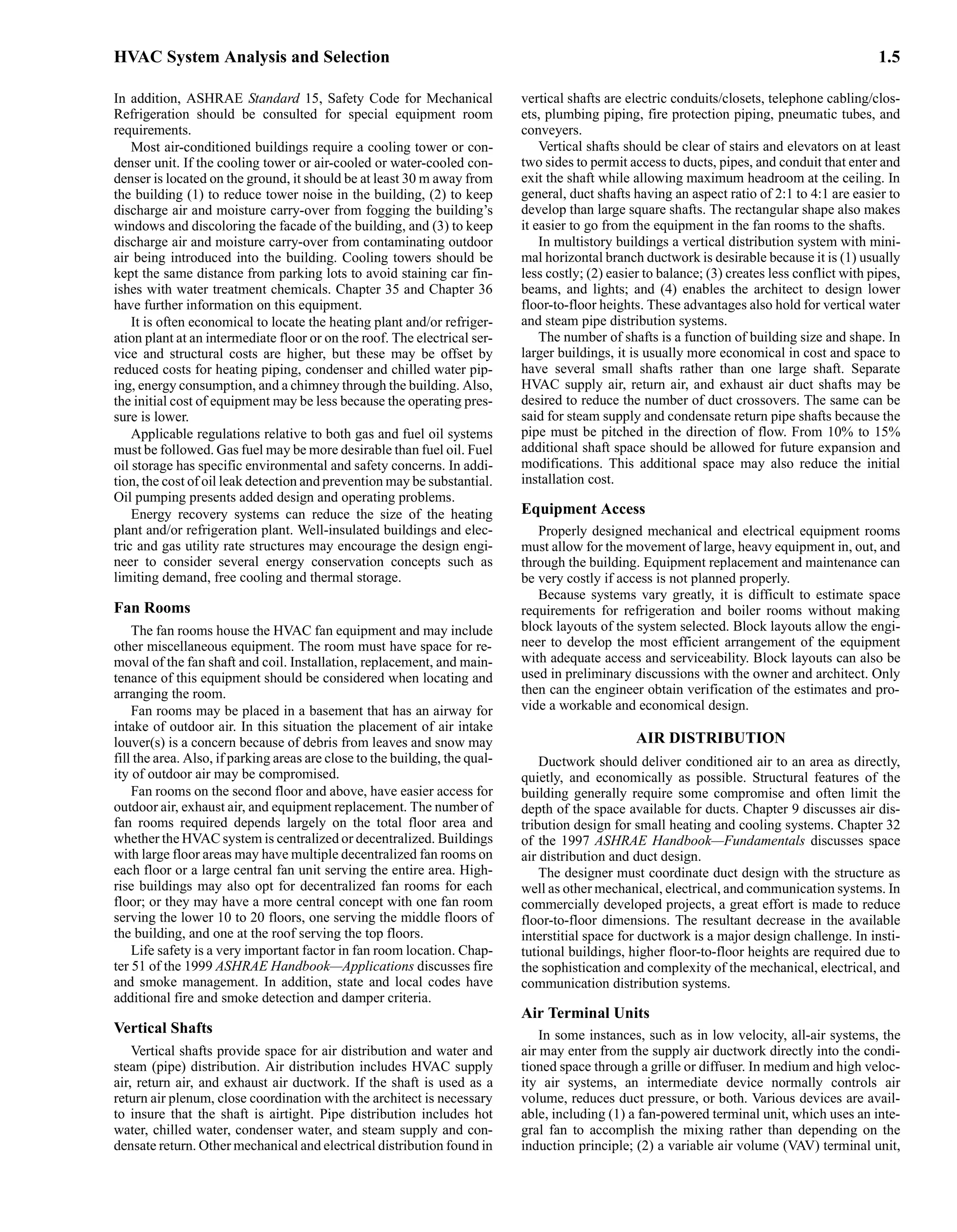
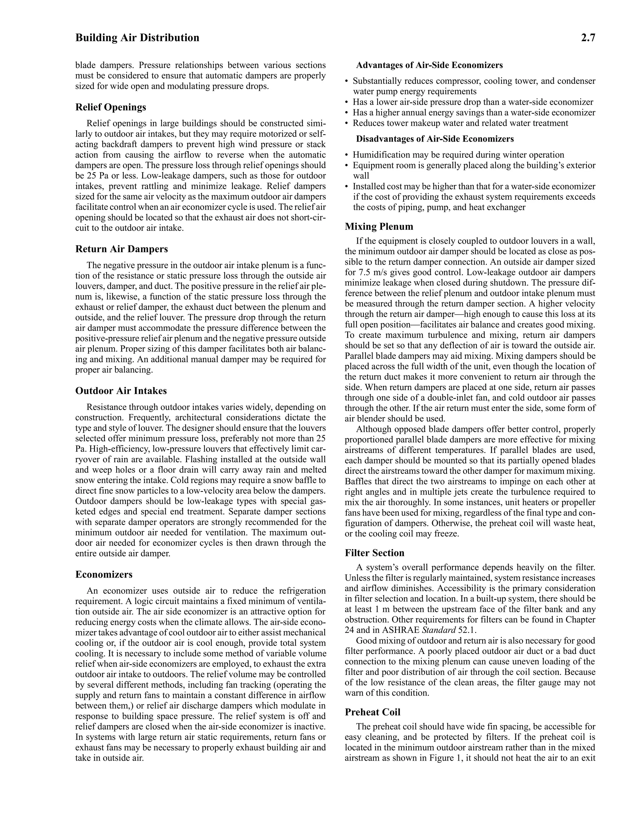
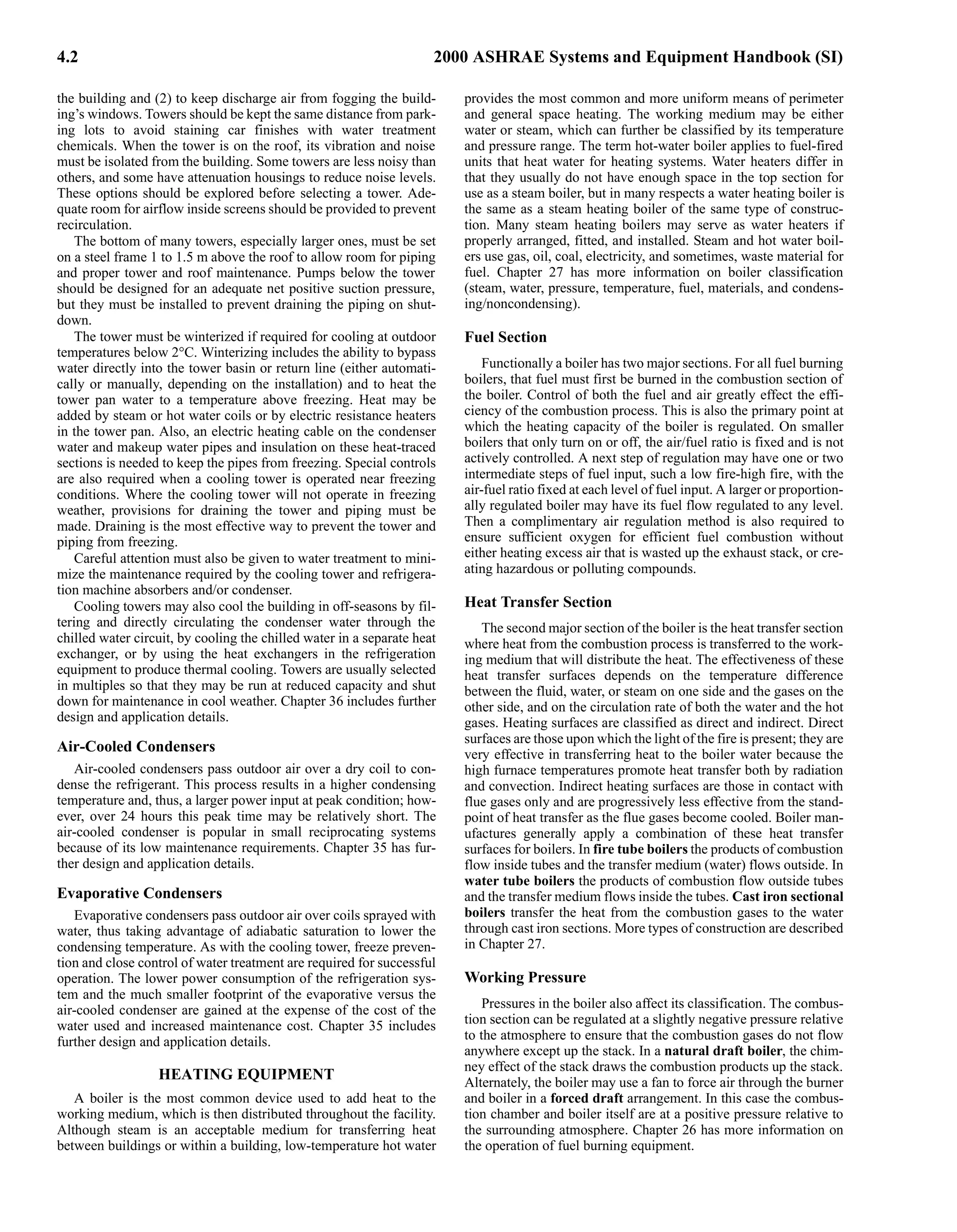
In cooling, tp is less than ta, so qc is negative. Figure 3 shows
heat transfer by natural convection at floor, wall, and ceiling heat-
ing panels as calculated from Equations (10), (11), (9a), and (9b),
respectively.
Figure 4 compares heat removal by natural convection at cooled
ceiling panel surfaces, as calculated by Equation (10), with data from
Wilkes and Peterson (1938) for specific panel sizes. An additional
curve illustrates the effect of forced convection on the latter data.
Similar adjustmentof the data from Minetal. (1956)isinappropriate,
but the effects would be much the same.
Combined Heat Transfer (Radiation and Convection)
The combined heat transfer from a panel surface can be deter-
mined by adding the radiant heat transfer qr as calculated by
Equation (5) (or from Figure 1 and Figure 2) to the convective
heat transfer qc as calculated from Equations (9a), (9b), (10), or
(11) or from Figure 3 or Figure 4, as appropriate.
Equation (5) requires the AUST for the room. In calculating the
AUST, the surface temperature of interior wall is assumed to be the
same as the room air temperature. The inside surface temperature tw
of outside walls and exposed floors or ceilings can be calculated
from the following heat transfer relationship:
(12)
or
(13)
where
h = inside surface conductance of exposed wall or ceiling
U = overall wall heat transfer coefficient of wall, ceiling, or floor,
W/(m2·K)
ta = room air temperature, °C
tu = inside surface temperature of outside wall, °C
to = outside air temperature, °C
From Table 1 in Chapter 24 of the 1997 ASHRAE Handbook—
Fundamentals:
h = 9.26 W/(m2·K) for a horizontal surface with heat flow up
h = 9.09 W/(m2·K) for a vertical surface (wall)
h = 8.29 W/(m2·K) for a horizontal surface with heat flow down
Figure 5 is a plot of Equation (13) for a vertical outdoor wall with
21°C room air temperature and h = 9.09 W/(m2·K). For rooms with
temperatures above or below 21°C, the values in Figure 5 can be
corrected by the factors plotted in Figure 6.
Tests by Schutrum et al. (1953a, 1953b) and simulations by Kal-
isperis (1985)based on a program developed by Kalisperis and Sum-
mers (1985) show that the AUST and room temperature are almost
equal, if there is little or no outdoor exposure. Steinman et al. (1989)
noted that this argument may not be appropriate for enclosures with
large glass areas or a high percentage of outside wall and/or ceiling
surface area. These cold surfaces have a lower AUST, which
increases the radiant heat transfer.
Fig. 3 Natural-Convection Heat Transfer at Floor,
Ceiling, and Wall Panel Surfaces
[Equations (9a), (9b), (10), and (11)]
Fig. 4 Heat Removal by Ceiling Cooling Panels with
Natural Convection [Equation (10)]
qc 2.13 tp ta
– 0.31 tp ta
–
( )
=
qc 1.78 tp ta
– 0.32
tp ta
–
( )
=
h ta tu
–
( ) U ta to
–
( )
=
tu ta
U
h
---
- ta to
–
( )
–
=](https://image.slidesharecdn.com/ashrae2000heatingventilationairconditioningequipmenthandbook-221028112511-3dff6ef4/75/Ashrae-2000-Heating-Ventilation-Air-Conditioning-Equipment-Handbook-pdf-52-2048.jpg)


![Panel Heating and Cooling 6.11
procedures covered in Chapters 24 through 29 of the 1997 ASHRAE
Handbook—Fundamentals. The procedure is as follows:
A. Cooling
1. Determine room design dry-bulb temperature, relative
humidity, and dew point.
2. Calculate room sensible and latent heat gains.
3. Select mean water temperature for cooling.
4. Establish minimum supply air quantity.
5. Calculate latent cooling available from air.
6. Calculate sensible cooling available from air.
7. Determine panel cooling load.
8. Determine panel area for cooling.
B. Heating
1. Designate room design dry-bulb temperature for heating.
2. Calculate room heat loss.
3. Select mean water temperature for heating.
4. Determine surface temperatures of unheated surfaces. Use Equa-
tion (13) to find surface temperatures of exterior walls and
exposed floors and ceilings. Interior walls are assumed to have
surface temperatures equal to the room air temperature.
5. Determine AUST of surfaces in room.
6. Determine surface temperature of heated radiant surface. Refer
to Figure 9 and Figure 10 if AUST does not greatly differ from
room air temperature. Use Equations (5), (9a), (9b), (10), and
(11) or refer to Figure 1 and Figure 3 otherwise.
7. Determine panel area for heating. Refer to Figure 9 and Figure
10 if AUST does not vary greatly from room air temperature.
Refer to manufacturers’ data for panel surface temperatures
higher than those given in Figure 9 and Figure 10.
8. Design the panel arrangement.
C. Both Heating and Cooling
1. Check thermal comfort requirements in the following steps [see
Chapter 8 of the 1997 ASHRAE Handbook—Fundamentals and
NRB (1981)].
(a) Determine occupant’s clothing insulation value and meta-
bolic rate (see Tables 4, 7, and 8 in Chapter 8 of the 1997
ASHRAE Handbook—Fundamentals).
(b) Determine the optimum operative temperature at the cold-
est point in the room (see Figure 15 in Chapter 8 of the 1997
ASHRAE Handbook—Fundamentals for other values).
(c) Determine the MRT at the coldest point in the room [see
Fanger (1972)].
(d) From the definition of operative temperature, establish the
optimum room design temperature at the coldest point in
the room. If the optimum room design temperature varies
greatly from the designated room design temperature, des-
ignate a new temperature.
(e) Determine the MRT at the hottest point in the room.
(f) Calculate the operative temperature at the hottest point in
the room.
(g) Compare the operative temperatures at the hottest and cold-
est points in the room. For light activity and normal cloth-
ing, the acceptable operative temperature range is 20 to
24°C [see NRB (1981) for other ranges]. If the range is not
acceptable, the heating system must be modified.
(h) Calculate radiant temperature asymmetry (NRB 1981).
Acceptable ranges are less than 10 K for windows and less
than 5 K for warm ceilings.
2. Determine water flow rate and pressure drop. Refer to manufac-
turers’ guides for specific products, or use the guidelines in
pages 33.1 through 33.6 of the 1997 ASHRAE Handbook—
Fundamentals. Chapter 12 of this volume also has information
on hydronic heating and cooling systems.
The supply and return manifolds need to be carefully designed. If
there are circuits of unequal coil lengths, the following equations
may be used (Hansen 1985; Kilkis 1998) for a circuit i connected to
a manifold with n circuits:
(22)
where
Leq = , m
Qi = flow rate in circuit i, L/s
Qtot =total flow rate in supply manifold, L/s
Li = coil length of circuit i, m
r = 1.75 for hydronic panels (Siegenthaler 1995)
The application, design, and installation of panel systems have
certain requirements and techniques:
1. As with any hydronic system, look closely at the piping system
design. Piping should be designed to ensure that water of the
proper temperature and in sufficient quantity is available to
every grid or coil at all times. Proper piping and system design
should minimize the detrimental effects of oxygen on the sys-
tem. Reverse-return systems should be considered to minimize
balancing problems.
2. Individual panels can be connected for parallel flow using
headers, or for sinuous or serpentine flow. To avoid flow irreg-
ularities within a header-type grid, the water channel or lateral
length should be greater than the header length. If the laterals in
a header grid are forced to run in a short direction, this problem
can be solved by using a combination series-parallel arrange-
ment. Serpentine flow will ensure a more even panel surface
temperature throughout the heating or cooling zone.
3. Noise from entrained air, high-velocity or high-pressure-drop
devices, or pump and pipe vibrations must be avoided. Water
velocities should be high enough to prevent separated air from
accumulating and causing air binding. Where possible, avoid
automatic air venting devices over ceilings of occupied spaces.
4. Design piping systems to accept thermal expansion adequately.
Do not allow forces from piping expansion to be transmitted to
panels. Thermal expansion of the ceiling panels must be con-
sidered.
5. In circulating water systems, plastic, rubber, steel, and copper
pipe or tube are used widely in ceiling, wall, or floor panel con-
struction. Where coils are embedded in concrete or plaster, no
threaded joints should be used for either pipe coils or mains.
Steel pipe should be the all-welded type. Copper tubing should
be soft-drawn coils. Fittings and connections should be mini-
mized. Changes in direction should be made by bending. Sol-
der-joint fittings for copper tube should be used with a
medium-temperature solder of 95% tin, 5% antimony, or capil-
lary brazing alloys. All piping should be subjected to a hydro-
static test of at least three times the working pressure. Maintain
adequate pressure in embedded piping while pouring concrete.
6. Placing the thermostat on a side wall where it can see the out-
side wall and the warm panel should be considered. The normal
thermostat cover reacts to the warm panel, and the radiant
effect of the panel on the cover tends to alter the control point
so that the thermostat controls 1 to 2 K lower when the outdoor
temperature is a minimum and the panel temperature is a max-
imum. Experience indicates that radiantly heated rooms are
more comfortable under these conditions than when the ther-
mostat is located on a back wall.
7. If throttling valve control is used, either the end of the main
should have a fixed bypass, or the last one or two rooms on the
mains should have a bypass valve to maintain water flow in the
Qi Leq Li
⁄
( )
1 r
⁄
Qtot
=
Li
1 r
⁄
–
i=1
n
∑
r
–](https://image.slidesharecdn.com/ashrae2000heatingventilationairconditioningequipmenthandbook-221028112511-3dff6ef4/75/Ashrae-2000-Heating-Ventilation-Air-Conditioning-Equipment-Handbook-pdf-59-2048.jpg)


![Panel Heating and Cooling 6.15
Coils are usually the sinuous type, although some header or grid-
type coils have been used in ceilings. Coils may be plastic, ferrous,
or nonferrous pipe or tube, with coil pipes spaced from 110 to
230 mm on centers, depending on the required output, pipe or tube
size, and other factors.
Whereplasteringisappliedtopipecoils,astandardthree-coatgyp-
sum plastering specification is followed, with a minimum of 10 mm
of cover below the tubes when they are installed below the lath. Gen-
erally, the surface temperature of plaster panels should not exceed
50°C. This can be accomplished by limiting the water temperature in
the pipes or tubes in contact with the plaster to a maximum tempera-
ture of 60°C. Insulation should be placed above the coils to reduce
back loss, the difference between heat supplied to the coil and netuse-
ful output to the heated room.
To protect the plaster installation and to ensure proper air dry-
ing, heat must not be applied to the panels for two weeks after all
plastering work has been completed. When the system is started
for the first time, the water supplied to the panels should not be
higher than 10 K above the prevailing room temperature at that
time and not in excess of 32°C. Water should be circulated at this
temperature for about two days, then increased at a rate of about
3 K per day to 60°C.
During the air-drying and preliminary warm-up periods, there
should be adequate ventilation to carry moisture from the panels. No
paint or paper should be applied to the panels before these periods
have been completed or while the panels are being operated. After
paint and paper have been applied, an additional shorter warm-up
period, similar to first-time starting, is also recommended.
Hydronic Wall Panels
Although piping embedded in walls is not as widely used as floor
and ceiling panels, it can be constructed by any of the methods out-
lined for ceilings or floors. Its design is similar to other hydronic
panels [see Equations (18) to (21)]. Heat transfer at the surface of
wall panels is given by Equations (5) and (11).
Hydronic Floor Panels
Interest has increased in radiant floor heating with the introduc-
tion of nonmetallic tubing and new design, application, and control
techniques. Whichever method is used for optimum floor output
and comfort, it is important that the heat be evenly distributed over
the floor. Spacing is generally 100 to 300 mm on centers for the
coils. Wide spacing under tile or bare floors can cause uneven sur-
face temperatures.
Embedded Piping in Concrete Slab. Plastic, rubber, ferrous,
and nonferrous pipe and tube are used in floor slabs that rest on
grade. The coils are constructed as sinuous-continuous pipe coils or
arranged as header coils with the pipes spaced from 150 to 450 mm
on centers. The coils are generally installed with 40 to 100 mm of
cover above them. Insulation is recommended to reduce the perim-
eter and back losses. Figure 20 shows the application of pipe coils
in slabs resting on grade. Coils should be embedded completely and
should not rest on an interface. Any supports used for positioning
the heating coils should be nonabsorbent and inorganic. Reinforcing
steel, angle iron, pieces of pipe or stone, or concrete mounds can be
used. No wood, brick, concrete block, or similar materials should
support coils. A waterproofing layer is desirable to protect insula-
tion and piping.
Where coils are embedded in structural load-supporting slabs
above grade, construction codes may affect theirposition. Otherwise,
the coil piping is installed as described for slabs resting on grade.
The warm-up and start-up period for concrete panels are similar
to those outlined for plaster panels.
Embedded systems may fail sometime during their life. Ade-
quate valves and properly labeled drawings will help isolate the
point of failure.
Suspended Floor Piping. Piping may be applied on or under
suspended wood floors using several methods of construction. Pip-
ing may be attached to the surface of the floor and embedded in a
layer of concrete or gypsum, mounted in or below the subfloor, or
attached directly to the underside of the subfloor using metal panels
to improve heat transfer from the piping. An alternate method is to
install insulation with a reflective surface and leave an air gap of 50
to 100 mm to the subfloor. Whichever method is used for optimum
floor output and comfort, it is important that the heat be evenly dis-
tributed throughout the floor. Pipes are generally spaced 100 to 300
mm apart. Wide spacing under tile or bare floors can cause uneven
surface temperatures.
Figure 21 illustrates construction with piping embedded in con-
crete or gypsum. The thickness of the embedding material is gener-
ally 25 to 50 mm when applied to a wood subfloor. Gypsum products
specifically designed for floor heating can generally be installed 25
to 40 mm thick because they are more flexible and crack-resistant
than concrete. When concrete is used, it should be of structural qual-
ity to reduce cracking due to movement of the wood frame or shrink-
age. The embedding material must provide a hard, flat, smooth
surface that can accommodate a variety of floor coverings.
As illustrated in Figure 22, tubing may also be installed in the
subfloor. The tubing is installed on top of the rafters between the
subflooring members. Heat diffusion and surface temperature can
be improved uniformly by the addition of metal heat transfer plates,
Fig. 20 Coils in Floor Slab on Grade Fig. 21 Embedded Tube in Thin Slab](https://image.slidesharecdn.com/ashrae2000heatingventilationairconditioningequipmenthandbook-221028112511-3dff6ef4/75/Ashrae-2000-Heating-Ventilation-Air-Conditioning-Equipment-Handbook-pdf-63-2048.jpg)

![Panel Heating and Cooling 6.17
Electric cables for panel heating have electrically insulated cov-
erings resistant to medium temperature, water absorption, aging
effects, and chemical action with plaster, cement, or ceiling lath
material. This insulation is normally a polyvinyl chloride (PVC)
covering, which may have a nylon jacket. The outside diameter of
the insulation covering is usually about 3 mm.
For plastered ceiling panels, the heating cable may be stapled to
gypsum board, plaster lath, or similar fire-resistant materials with
rust-resistant staples (Figure 25). With metal lath or other conduct-
ing surfaces, a coat of plaster (brown or scratch coat) is applied to
completely cover the metal lath or conducting surface before the
cable is attached. After the lath is fastened on and the first plaster
coat is applied, each cable is tested for continuity of circuit and for
insulation resistance of at least 100 kΩ measured to ground.
The entire ceiling surface is finished with a covering of thermally
noninsulating sand plaster about 13 to 19 mm thick or other approved
noninsulating material applied according to manufacturer’s specifi-
cations. The plaster is applied parallel to the heating cable rather than
across the runs. While new plaster is drying, the system should not be
energized, and the range and rate of temperature change should be
kept low by other heat sources or by ventilation until the plaster is
thoroughly cured. Vermiculite or other insulating plaster causes
cables to overheat and is contrary to code provisions.
For laminated drywall ceiling panels, the heating cable is placed
between two layers of gypsum board, plasterboard, or other ther-
mally noninsulating fire-resistant ceiling lath. The cable is stapled
directly to the first (or upper) lath, and the two layers are held apart
by the thickness of the heating cable. It is essential that the space
between the two layers of lath be completely filled with a noninsu-
lating plaster or similar material. This fill holds the cable firmly in
place and improves heat transfer between the cable and the finished
ceiling. Failure to fill the space between the two layers of plaster-
board completely may allow the cable to overheat in the resulting
voids and may cause cable failure. The plaster fill should be applied
according to manufacturer’s specifications.
Electric heating cables are ordinarily installed with a 150 mm
nonheating border around the periphery of the ceiling. A 200 mm
clearance must be provided between heating cables and the edges of
the outlet or junction boxes used for surface-mounted lighting fix-
tures. A 50 mm clearance must be provided from recessed lighting
fixtures, trim, and ventilating or other openings in the ceiling.
Heating cables or panels must be installed only in ceiling areas
that are not covered by partitions, cabinets, or other obstructions.
However, it is permissible for a single run of isolated embedded
cable to pass over a partition.
The National Electrical Code (NFPA Standard 70) requires that
all general power and light wiring be run above the thermal insula-
tion or at least 50 mm above the heated ceiling surface, or that the
wiring be derated.
In drywall ceiling construction, the heating cable is always
installed with the cable runs parallel to the joist. A 65 mm clearance
between adjacent cable runs must be left centered under each joist
for nailing. Cable runs that cross over the joist must be kept to a min-
imum. Where possible, these crossings should be in a straight line at
one end of the room.
For cable having a power density of 9 W/m, the minimum per-
missible spacing is 40 mm between adjacent runs. Some manufac-
turers recommend a minimum spacing of 50 mm for drywall
construction.
The spacing between adjacent runs of heating cable can be deter-
mined using the following equation:
(23)
where
M = cable spacing, mm
An = net panel heated area, m2
C = length of cable, m
Net panel area An in Equation (23) is the net ceiling area avail-
able after deducting the area covered by the nonheating border,
lighting fixtures, cabinets, and other ceiling obstructions. For sim-
plicity, Equation (23) contains a slight safety factor, and small light-
ing fixtures are usually ignored in determining net ceiling area.
Resistance of the electric cable must be adjusted according to its
temperature at design conditions (Ritter and Kilkis 1998):
(24)
where
R = electrical resistance of electric cable at standard temperature
(20°C), Ω/m
αe = thermal coefficient for material resistivity, °C −1
αo = thermal expansion coefficient, °C −1
td = surface temperature of electric cable at operating conditions [see
Equation (18)], °C
The 65 mm clearance required under each joist for nailing in dry-
wall applications occupies one-fourth of the ceiling area if the joists
are 400 mm on centers. Therefore, for drywall construction, the net
area An must be multiplied by 0.75. Many installations have a spac-
ing of 40 mm for the first 600 mm from the cold wall. Remaining
cable is then spread over the balance of the ceiling.
Electrically Heated Wall Panels
Cable embedded in walls similar to ceiling construction is used in
Europe. Because of possible damage from nails driven for hanging
pictures or from building alterations, most codes in the United States
prohibit such panels. Some of the prefabricated panels described in
the preceding section are also used for wall panel heating.
Electrically Heated Floors
Electric heating cable assemblies such as those used for ceiling
panels are sometimes used for concrete floor heating systems.
Because the possibility of cable damage during installation is
greater for concrete floor slabs than for ceiling panels, these assem-
blies must be carefully installed. After the cable has been placed, all
unnecessary traffic should be eliminated until the concrete covering
has been placed and hardened.
Table 4 Characteristics of Typical Electric Panel Heater
Resistor material Graphite or nichrome wire
Relative heat intensity Low, 540 to 1350 W/m2
Resistor temperature 80 to 180°C
Envelope temperature (in use) 70 to 150°C
Radiation-generating ratioa 0.7 to 0.8
Response time (heat-up) 240 to 600 s
Luminosity (visible light) None
Thermal shock resistance Excellent
Vibration resistance Excellent
Impact resistance Excellent
Resistance to drafts or windb Poor
Mounting position Any
Envelope material Steel alloy or aluminum
Color blindness Very good
Flexibility Good—wide range of power density,
length, and voltage practical
Life expectancy Over 10 000 h
aRatio of radiant output to power input (elements only).
bMay be shielded from wind effects by louvers, deep-drawn fixtures, or both.
M 1000An C
⁄
=
R′ R
1 αe td 20
–
( )
+
[ ]
1 αo td 20
–
( )
+
[ ]
-----------------------------------------
-
=](https://image.slidesharecdn.com/ashrae2000heatingventilationairconditioningequipmenthandbook-221028112511-3dff6ef4/75/Ashrae-2000-Heating-Ventilation-Air-Conditioning-Equipment-Handbook-pdf-65-2048.jpg)


![Cogeneration Systems and Engine and Turbine Drives 7.11
Delayed Capacity Addition. With the increased generation
capacity provided by a CTIAC system, the addition of actual or
reserve generation capacity can be delayed.
Baseload Efficiency Improvements. An ice or chilled water
TES system can help level the baseload of a power generation facil-
ity by storing energy using electric chiller equipment during off-
peak periods; this tends to increase the efficiency of power produc-
tion. Electric chillers operated at cooler nighttime temperatures are
more efficient and operate at reduced condenser temperatures,
which can also use less source energy.
When maximum power is desired every hour of the year, a con-
tinuous CTIAC system is justified in warm climates to maximize
turbine output and minimize heat rate.
Other Benefits. Other advantages include the following:
• Evaporative media filter the inlet air.
• CTIAC systems that reduce the air temperature below saturation
can produce a significant amount of condensed water, a poten-
tially valuable resource that can also provide makeup water for
cooling towers or evaporative condensers.
• CTIAC systems are simple, energized only when required.
• Emissions can decrease due to increased overall efficiency.
• A CTIAC system can match the inlet air temperature to the
required turbine generating capacity, allowing 100% open inlet
guide vanes, which eliminate inlet guide vane pressure loss pen-
alties.
Disadvantages
• CTIACsystemsrequireadditionalspaceandincreasemaintenance.
• Evaporative media or cooling coils pose a constant inlet air pres-
sure loss.
INSTRUMENTS AND CONTROLS
Control systems are typically microprocessor based. The con-
trol system sequences all systems during starting and running,
monitors performance, and protects the equipment. The operator
interface is a monitor and keyboard with analog gages provided for
redundancy.
Where operating the gas turbine engine at the unit’s maximum
rating is desirable, the load is controlled based on the temperature
of the combustion gases in the turbine section and on the ambient
air temperature. When the engine combustion gas temperature
reaches a set value, the control system begins to control the engine
so that the load (and therefore the temperature) does not increase
further. With changes in the ambient air temperature, the control
system adjusts the load to maintain the set temperature value in the
gas engine’s turbine section. Where maintaining a constant load
level is desirable, the control system allows the operator to dial in
any load, and the system controls the engine accordingly.
PERFORMANCE CHARACTERISTICS
The rating of a gas turbine is greatly affected by altitude, ambient
temperature, inlet pressure to the air compressor, and exhaust pres-
sure from the turbine. In most applications, filters and silencers
must be installed in the air inlet. Silencers, waste heat boilers, or
both are used on the exhaust. The pressure drop of these accessories
and piping losses must be considered when determining the power
output of the unit.
Gas turbine ratings are usually given at standard conditions
defined by the International Organization for Standardization
(ISO): 15°C, 60% rh, and sea level pressure at the inlet flange of the
air compressor and the exhaust flange of the turbine. Corrections for
other conditions must be obtained from the manufacturer, as they
vary with each model depending primarily on gas turbine efficiency.
Inlet air cooling has been used to increase capacity. The following
approximations may be used for design:
• Each 10 K rise in inlet temperature decreases power output by
9%.
• An increase of 300 m in altitude decreases power output by
approximately 3.5%.
• Inlet pressure loss in filter, silencer, and ducting decreases power
output by approximately 2% per kPa pressure loss.
• Discharge pressure loss in boiler, silencer, and ducting
decreases power output by approximately 1.2% per kPa pres-
sure loss.
Gas turbines operate with a wide range of fuels. For refrigeration
service, a natural gas system is usually provided with an option of a
standby No. 1 or 2 grade fuel oil system.
Figure 15 shows a typical performance curve for a 7.5 MW tur-
bine engine. For example, at an air inlet temperature of 30°C, the
engine develops its maximum power at about 82% of maximum
speed. The shaft thermal efficiency of the prime mover is 18 to
36% with exhaust gases from the turbine ranging from 430 to
530°C. If the exhaust heat can be used, overall thermal efficiency
can increase.
Figure 13B shows a regenerator that uses the heat of the exhaust
gases to heat the air from the compressor prior to combustion. Over-
all shaft efficiency can be increased to between 28 and 38% by using
a regenerator or recuperator.
If process heat is required, the exhaust can satisfy a portion of
that heat, and the combined system is a cogeneration system. The
exhaust can be used (1) directly as a source of hot air, (2) in a large
boiler or furnace as a source of preheated combustion air (the
exhaust contains about 16% oxygen), or (3) to heat a process or
working fluid such as the steam system shown in Figure 16. Overall
thermal efficiency is [(shaft energy + heat energy) × 100] ⁄ (fuel
energy). Thermal efficiencies of these systems vary from 50% to
greater than 90%. The exhaust of a gas turbine has about 5.7 to
11.3 MJ of available heat per watt.
Additionally, because of the high oxygen content, the exhaust
stream can support the combustion of an additional 40 MJ of fuel
per watt. This additional heat can then be used in general manufac-
turing processes.
Fig. 15 Turbine Engine Performance Characteristics](https://image.slidesharecdn.com/ashrae2000heatingventilationairconditioningequipmenthandbook-221028112511-3dff6ef4/75/Ashrae-2000-Heating-Ventilation-Air-Conditioning-Equipment-Handbook-pdf-79-2048.jpg)


![Cogeneration Systems and Engine and Turbine Drives 7.19
• Applications where the fuel source is inexpensive, such as munic-
ipal waste, process gas, or waste streams in which incineration
with waste heat recovery can be applied
• District heating/cooling plants that have high process loads, ther-
mal loads, or both
THERMAL OUTPUT AND RECOVERY
THERMAL OUTPUT CHARACTERISTICS
Cogeneration provides an opportunity to use the fuel energy that
the prime mover does not convert into shaft energy. If the heat can-
not be used effectively, the plant efficiency is limited to that of the
prime mover. However, if the site heat energy requirements can be
met effectively by the normally wasted heat at the level it is avail-
able from the prime mover, this salvaged heat will reduce the nor-
mal fuel requirements of the site and increase overall plant
efficiency. The prime mover furnishes (1) mechanical energy from
the shaft and (2) unused heat energy that remains after the fuel or
steam has acted on the shaft. Shaft loads (generators, centrifugal
chillers, compressors, and process equipment) require a given
amount of rotating mechanical energy. Once the prime mover is
selected to provide the required shaft output, it has a fixed relation-
ship to heat availability and system efficiency, depending on the
prime mover fuels versus heat balance curves. The ability to use the
prime mover waste heat determines overall system efficiency and is
one of the critical factors in economic feasibility.
Reciprocating Engines
In all reciprocating internal combustion engines except small air-
cooled units, heat can be reclaimed from the jacket cooling system,
lubricating system, turbochargers, exhaust, and aftercoolers. These
engines require extensive cooling to remove excess heat not con-
ducted into the power train during combustion and the heat resulting
from friction. Coolant fluids and lubricating oil are circulated to
remove this engine heat. Some engines permit the coolant to reach
120°C at above atmospheric pressure, which allows the coolant to
flash into low-pressure steam [100 kPa (gage)] after it has left the
engine jacket (ebullient cooling).
Waste heat in the form of hot water or low-pressure steam is
recovered from the engine jacket manifolds and exhaust, and addi-
tional heat can be recovered from the lubrication system (see Figure
30 through Figure 34).
Provisions similar to those used with gas turbines are necessary
if supplemental heat is required, except an engine exhaust is rarely
fired with a booster because it contains insufficient oxygen. If elec-
trical supplemental heat is used, the additional electrical load is
reflected back to the prime mover, which reacts accordingly by pro-
ducing additional waste heat. This action creates a feedback effect,
which can stabilize system operation under certain conditions. The
approximate distribution of input fuel energy under selective con-
trol of the thermal demand for an engine operating at rated load is as
follows:
Shaft power 33%
Convection and radiation 7%
Rejected in jacket water 30%
Rejected in exhaust 30%
These amounts vary with engine load and design. Four-cycle engine
heat balance for naturally aspirated (Figure 27) and turbocharged
gas engines (Figure 28) show typical heat distribution. The exhaust
gas temperature for these engines is about 650°C at full load and
540°C at 60% load.
Two-cycle lower speed (900 rpm and below) engines operate at
lower exhaust gas temperatures, particularly at light loads, because
the scavenger air volumes remain high through the entire range of
Fig. 27 Heat Balance for Naturally Aspirated Engine
Fig. 28 Heat Balance for Turbocharged Engine](https://image.slidesharecdn.com/ashrae2000heatingventilationairconditioningequipmenthandbook-221028112511-3dff6ef4/75/Ashrae-2000-Heating-Ventilation-Air-Conditioning-Equipment-Handbook-pdf-87-2048.jpg)


![7.26 2000 ASHRAE Systems and Equipment Handbook (SI)
opens to allow steam to flow through the low-pressure section,
where additional power is generated.
An automatic extraction turbine (Figure 42) is uniquely designed
to meet the specific power and heat capability of a given site;
therefore, no simple relationship generally applies. For preliminary
design analyses, the procedures presented by Newman (1945) can
be used to estimate performance. The product of such an analysis is
a performance map similar to that shown in Figure 43 for a 5000 kW
generator. The performance map provides the steam flow to the tur-
bine as a function of generator output with extraction flow as a
parameter.
HEAT-ACTIVATED CHILLERS
Waste heat may be converted and used to produce chilled water
by several methods. The conventional method is to use hot water
(>93°C) or low-pressure steam [<100 kPa (gage)] in single-stage
absorption chillers. These single-stage absorbers have a COP of 0.6
or less; 1.7 kW of recovered heat can produce about 1 kW of cooling.
If a direct exhaust, two-stage absorption chiller is used, the equa-
tion to estimate cooling produced from recoverable heat is
(7)
where
q = cooling produced, kW
= mass flow of exhaust gas, kg/s
cp = specific heat of gas = 1.12 kJ/(kg·K)
t1 = exhaust temperature in, °C
t2 = exhaust temperature out = 190°C
1.14 = coefficient of performance
0.97 = connecting duct system efficiency
If it is available, the manufacturer’s COP rating should be used to
replace the assumed value.
For internal combustion engines, jacket water heat at 82 to 99°C
may be added to the recovered heat of the engine exhaust to produce
chilled water in a single-stage absorption machine. The equation to
estimate the cooling produced from the heat recovered from the
water is
(8)
where
= mass flow of water, kg/s
(cp)w = specific heat of water, 4.18 kJ/(kg·K)
t1 = water temperature out of engine, °C
t2 = water temperature returned to engine, °C
[Typically (t1 − t2) = 8 K.]
0.6 = COP
Heat may be recovered from engines and gas turbines as high-
pressure steam, depending on exhaust temperature. Steam pressures
from 100 to 1400 kPa (gage) are common. When steam is produced
at pressures over 300 kPa (gage), two-stage steam absorption chill-
ers can also be considered. The COP of a two-stage absorption
chiller is 1.14 or greater. The steam input required is 1.2 to 1.25
kg/kWh. This compares to 2.3 kg/kWh for the single-stage absorp-
tion machine using 100 kPa (gage) steam. Two-stage absorption
chillers can take advantage of the dual temperatures available from
the engine exhaust and jacket water.
The use of the engine exhaust heat to provide cooling is
described in the section on Exhaust Gas Heat Recovery, and some
absorption machines have been designed specifically for heat
recovery in cogeneration applications. These units use both the
jacket water and the exhaust gas directly. Ebullient cooling of the
engine is not required (Figure 44). These chillers range in capacity
from 175 to 700 kW.
Another type of absorption chiller uses gas engine or turbine
exhaust directly in a waste heat absorption chiller. These units are
available in sizes ranging from 350 to 5300 kW. Using oil/diesel
exhaust for this purpose has not been successful due to fouling and
corrosion problems in such direct-fired or waste exhaust-fired
chillers.
Fig. 42 Automatic Extraction Turbine
Cogeneration System
q m
·
ecp t1 t2
–
( ) 1.14 0.97
×
( )
=
m
·
e
q 0.6m
·
w cp
( )w
t1 t2
–
( )
=
m
·
w
Fig. 43 Performance Map of Automatic Extraction Turbine
Fig. 44 Exhaust Gas Chiller-Heater](https://image.slidesharecdn.com/ashrae2000heatingventilationairconditioningequipmenthandbook-221028112511-3dff6ef4/75/Ashrae-2000-Heating-Ventilation-Air-Conditioning-Equipment-Handbook-pdf-94-2048.jpg)


![Cogeneration Systems and Engine and Turbine Drives 7.41
unloaded start. The engine first speeds to one-half or two-thirds of
full speed. Then, a gradual cylinder load is added, and the engine
speed increases over a period of 2 to 3 min. In some applications,
such as an engine-driven heat pump, low-speed starting may cause
oil accumulation and sludge. As a result, a high-speed start is
required.
These systems operate at specific fuel consumptions (SFCs)
of approximately 0.3 to 0.5 m3/kWh [0.08 to 0.14 L/(kW·s)] of
pipeline quality natural gas (HHV = 37.3 MJ/m3) in sizes down to
90 kW. Comparable heat rates for diesel engines run from 10 to
13 MJ/kWh (2.8 to 3.5 W/W). Smaller units are also available.
Coolant pumps can also be driven by the engine. These direct-
connected pumps never circulate tower water through the engine
jacket. Figure 48 illustrates the fuel economy effected by varying
prime mover speed with reciprocating compressor load until the
machine is operating at about half its capacity. Below this level,
the load is reduced at essentially constant engine speed by
unloading the compressor cylinders.
Frequent operation at low engine idling speed may require an
auxiliary oil pump for the compressor. To reduce wear and assist in
starts, a tank-type lubricant heater or a crankcase heater and a
motor-driven auxiliary oil pump should be installed to lubricate the
engine with warm oil when it is not running. Refrigerant piping
practices for engine-driven units are the same as for motor-driven
units.
Engine-Driven Centrifugal Compressors. Packaged, engine-
driven centrifugal chillers that do not require field assembly are
available in capacities up to 7400 kW. Automotive derivative
engines modified for use on natural gas are typical of these smaller
packages because of their compact size and mass. These units may
be equipped with either manual or automatic start-stop systems and
engine speed controls.
Larger open-drive centrifugal chillers are usually field assembled
and normally include a compressor mounted on an individual base and
coupled by means of flanged pipes to an evaporator and a condenser.
The centrifugal compressor is driven through a speed increaser. Many
of these compressors operate at about six times the speed of the
engines; compressor speeds of up to 14 000 rpm have been used.
To effect the best compromise between the initial cost of the
equipment (engine, couplings, and transmission) and the mainte-
nance cost, engine speeds between 900 and 1200 rpm are generally
used. Engine output can be modulated by reducing engine speed. If
the operation at 100% of rated speed produces 100% of rated output,
approximately 60% of rated output is available at 75% of rated speed.
Capacity control of the centrifugal compressor can be achieved by
either variable inlet guide vane control with constant compressor
speed ora combination of variable-speed control and inlet guide vane
control, the latter providing the greatest operating economy.
Engine-Driven Heat Pumps. An additional economic gain can
result from operating an engine-driven refrigeration cycle as a heat
pump, provided that the facility has a thermal load profile that can
adequately absorb its 40 to 50°C low-quality heat. Using the same
equipment for both heating and cooling reduces capital investment.
A gas engine drive for heat pump operation also makes it possible to
operate in a cogeneration mode, which requires a somewhat larger
thermal load. Unless a major portion of this larger thermal recovery
can be absorbed, the cycle may not be economical.
For larger projects, the economics of engine or turbine genera-
tors combined with motor-driven chillers should be compared with
the economics of generators plus combustion engine or turbine-
driven chillers. Figure 49 shows the total energy available from a
typical engine-driven heat pump. Table 13 lists the economic coef-
ficients of performance (ECOPs) for various configurations. The
values in the table can be used to illustrate the difference between
the COP, the ECOP, and the thermal efficiency of this cycle. Here,
Fig. 48 Performance Curve for Typical 350 kW,
Gas Engine-Driven, Reciprocating Chiller
Table 13 Coefficient of Performance for
Engine-Driven Heat Pump
Item
Heat Source
Refrigerant
Condenser
Only,
MJ/MJ
Refrigerant
Condenser
and Jacket
Water,
MJ/MJ
Refrigerant
Condenser,
Jacket Water,
Exhaust Gas,
MJ/MJ
Total heat input to engine 1.00 1.00 1.00
Cooler heat rejection
to condenser (from build-
ing load)
1.20 1.20 1.20
Heat of compression 0.254 0.254 0.254
Heat from engine jacket
water heater
— 0.250 0.250
Heat from exhaust gas heater — — 0.300
Total heat to heating circuit 1.454 1.704 2.004
Economic coefficient
of performance
1.45 1.70 2.00
Fig. 49 Heat Balance for Engine-Driven Heat Pump](https://image.slidesharecdn.com/ashrae2000heatingventilationairconditioningequipmenthandbook-221028112511-3dff6ef4/75/Ashrae-2000-Heating-Ventilation-Air-Conditioning-Equipment-Handbook-pdf-109-2048.jpg)


![9.14 2000 ASHRAE Systems and Equipment Handbook (SI)
Table 3 Definitions of System Performance Factors
Comments
Equipment-Component efficiency factors
• Integrated energy over all
operating cycles
Equipment-System performance factors
• Efficiency of the furnace/duct
subsystem
• Accounts for heating by fugi-
tive gains
• Efficiency of the combined
HVAC system
Equipment-Load interaction factors
• Accounts for added loads due
to equipment operation
• Common index for ranking
system. Not an efficiency.
Energy cost factors
• System energy characteristics
• Economics
• Common economic index for
ranking systems
Annual energy use
AEU = Annual Energy Use (fuel and electricity) predicted by the HOUSE model, in common energy units
Annual Fuel Used = AEU / (1.0 + RAE)
Annual Electricity Used = AEU / (1.0 + 1/RAE)
Percent savings
% Energy Saving = 100 [IS − (IS)BC]/IS, where (IS)BC = IS for base case • Saving relative to base case
% Cost Saving = 100 [ISCM − (ISCM)BC]/ISCM, where (ISCM)BC = Cost-modified IS for base case
Other factors for dynamic performance
AFUE = Annual Fuel Utilization Efficiency by ANSI/ASHRAE Standard 103 efficiency rating, applicable to specific furnaces.
Values in this chapter are for generic furnaces.
SSE = Steady-State Efficiency value for a given furnace by ANSI Z21.47/ CSA 2.3 test procedure.
Note: Energy inputs and outputs are integrated over an annual period.
Efficiencies (E) are expressed as percents. Indexes (I), factors (F), and
ratios (R) are expressed as fractions.
aThe Total Heat Delivered is the integration over time of all the energy
supplied to the conditioned space by the HVAC equipment. By defini-
tion, it is exactly equal to the space-heating load.
bThe Induced Load Factor may be positive or negative, depending on the value of the load relative to
the selected base case.
cThe System Induced Load is the difference between the space-heating load for a particular case and
the space-heating load for the base case. For the base case, the System Induced Load is, by definition,
zero.
dIndexes are referenced to as “base cases” from which improvements are measured.
EF Furnace Efficiency 100
Furnace Output
Total Energy Input
--------------------------------------------
- 100
Duct Input
Total Energy Input
--------------------------------------------
-
= = =
ED Duct Efficiency 100
Duct Output
Duct Input
-----------------------------
= =
EHD Heat Delivery Efficiency
EF ED
×
100
-------------------
-
Duct Output
Total Energy Input
--------------------------------------------
-
= = =
FMG Miscellaneous Gain Factor
Total Heat Delivered
a
Duct Output
----------------------------------------------------
= =
ES System Efficiency EHD FMG
× 100
Total Heat Delivered
Total Energy Input
-------------------------------------------------
-
= = =
FIL Induced Load Factor
b System Induced Load
c
Total Heat Delivered
-----------------------------------------------------
-
= =
FLM Load Modification Factor 1.0 FIL
–
Total Heat Delivered System Induced Load
–
Total Heat Delivered
------------------------------------------------------------------------------------------------------------
-
= = =
IS System Index
d ES FLM
×
100
---------------------- Total Heat Delivered System Induced Load
–
Total Energy Input
------------------------------------------------------------------------------------------------------------
-
= = =
RAE Auxiliary Energy Ratio
Auxiliary Energy Input
Primary Energy Input
-------------------------------------------------------
- Electrical Energy Input
Fuel Energy Input
-------------------------------------------------------
-
= = =
RCL Local Energy Cost Ratio
Electrical Cost per Energy Unit
Reference Fuel Cost per Energy Unit
----------------------------------------------------------------------------------------
- (in common units)
= =
FCR Cost Ratio Factor
Fuel Energy Input Electric Energy Input
+
Fuel Energy Input RCL Electric Energy Input
( )
+
---------------------------------------------------------------------------------------------------------------------
1.0 RAE
+
1.0 RCL
+ RAE
×
--------------------------------------
-
= = =
Special Case (Fuel = 0): FCR 1 RCL
⁄
=
ISCM Cost-Modified System Index
d
IS FCR
×
Total Heat Delivered System Induced Load
–
Primary Energy Input RCL Auxiliary Energy Input
( )
+
-------------------------------------------------------------------------------------------------------------------------------
--
= = =](https://image.slidesharecdn.com/ashrae2000heatingventilationairconditioningequipmenthandbook-221028112511-3dff6ef4/75/Ashrae-2000-Heating-Ventilation-Air-Conditioning-Equipment-Handbook-pdf-152-2048.jpg)


![Steam Systems 10.5
The first step in selecting pressures is to analyze the load require-
ments. Space heating and domestic water heating can best be
served, directly or indirectly, with low-pressure steam less than
100 kPa (gage) or 120°C. Other systems that can be served with
low-pressure steam include single-stage absorption units [70 kPa
(gage)], cooking, warming, dishwashing, and snow melting heat
exchangers. Thus, from the standpoint of load requirements, high-
pressure steam [above 100 kPa (gage)] is required only for loads
such as dryers, presses, molding dies, power drives, and other pro-
cessing, manufacturing, and power requirements. The load require-
ment establishes the pressure requirement.
When the source is close to the load(s), the generation pressure
should be high enough to provide the (1) load design pressure, (2)
friction losses between the generator and the load, and (3) control
range. Losses are caused by flow through the piping, fittings, con-
trol valves, and strainers. If the generator(s) is located remote from
the loads, there could be some economic advantage in distributing
the steam at a higher pressure to reduce pipe size. When this is con-
sidered, the economic analysis should include the additional invest-
ment and operating costs associated with a higher pressure
generation system. When an increase in the generating pressure
requires a change from below to above 100 kPa (gage), the gener-
ating system equipment changes from low-pressure class to high-
pressure class and there are significant increases in both investment
and operating cost.
Where steam is provided from a nonfired device or prime mover
such as a diesel engine cooling jacket, the source device can have an
inherent pressure limitation.
PIPING
The piping system distributes the steam, returns the condensate,
and removes air and noncondensable gases. In steam heating sys-
tems, it is important that the piping distribute steam, not only at full
design load, but at partial loads and excess loads that can occur on
system warm-up. The usual average winter steam demand is less
than half the demand at the lowest outdoor design temperature.
However, when the system is warming up, the load on the steam
mains and returns can exceed the maximum operating load for the
coldest design day, even in moderate weather. This load comes from
raising the temperature of the piping to the steam temperature and
that of the building to the indoor design temperature. Supply and
return piping should be sized according to Chapter 33 of the 1997
ASHRAE Handbook—Fundamentals.
Supply Piping Design Considerations
1. Size pipe according to Chapter 33 of the 1997 ASHRAE Hand-
book—Fundamentals, taking into consideration pressure drop
and steam velocity.
2. Pitch piping uniformly down in the direction of steam flow at 2
mm per metre. If piping cannot be pitched down in the direc-
tion of the steam flow, refer to Chapter 33 of the 1997 ASHRAE
Handbook—Fundamentals for rules on pipe sizing and pitch.
3. Insulate piping well to avoid unnecessary heat loss (see
Chapters 22 and 23 of the 1997 ASHRAE Handbook—
Fundamentals).
4. Condensate from unavoidable heat loss in the distribution sys-
tem must be removed promptly to eliminate water hammer and
degradation of steam quality and heat transfer capability.
Install drip legs at all low points and natural drainage points in
the system, such as at the ends of mains and the bottoms of ris-
ers, and ahead of pressure regulators, control valves, isolation
valves, pipe bends, and expansion joints. On straight horizontal
runs with no natural drainage points, space drip legs at intervals
not exceeding 90 m when the pipe is pitched down in the direc-
tion of the steam flow and at a maximum of 45 m when the pipe
is pitched up, so that condensate flow is opposite of steam flow.
These distances apply to systems where valves are opened
manually to remove air and excess condensate that forms dur-
ing warm-up conditions. Reduce these distances by about half
in systems that are warmed up automatically.
5. Where horizontal piping must be reduced in size, use eccentric
reducers that permit the continuance of uniform pitch along the
bottom of piping (in downward pitched systems). Avoid con-
centric reducers on horizontal piping, because they can cause
water hammer.
6. Take off all branch lines from the top of the steam mains, pref-
erably at a 45° angle, although vertical 90° connections are
acceptable.
7. Where the length of a branch takeoff is less than 3 m, the
branch line can be pitched back 4 mm per metre, providing drip
legs as described previously in (4).
8. Size drip legs properly to separate and collect the condensate.
Drip legs at vertical risers should be full-size and extend
beyond the riser, as shown in Figure 4. Drip legs at other loca-
tions should be the same diameter as the main. In steam mains
150 mm and over, this can be reduced to half the diameter of
the main, but to no less than 100 mm. Where warm-up is super-
vised, the length of the collecting leg is not critical. However,
the recommended length is one and a half times the pipe diam-
eter and not less than 200 mm. For automatic warm-up, collect-
ing legs should always be the same size as the main and should
be at least 710 mm long to provide the hydraulic pressure dif-
ferential necessary for the trap to discharge before a positive
pressure is built up in the steam main.
9. Condensate should flow by gravity from the trap to the return
piping system. Where the steam trap is located below the
return line, the condensate must be lifted. In systems operating
above 275 kPa (gage), the trap discharge can usually be piped
directly to the return system (Figure 5). However, back pres-
sure at the trap discharge (return line pressure plus hydraulic
pressure created by height of lift) must not exceed steam main
pressure, and the trap must be sized after considering back
pressure. A collecting leg must be used and the trap discharge
must flow by gravity to a vented condensate receiver, from
Fig. 4 Method of Dripping Steam Mains](https://image.slidesharecdn.com/ashrae2000heatingventilationairconditioningequipmenthandbook-221028112511-3dff6ef4/75/Ashrae-2000-Heating-Ventilation-Air-Conditioning-Equipment-Handbook-pdf-161-2048.jpg)


![10.10 2000 ASHRAE Systems and Equipment Handbook (SI)
the reducing valve of the second-stage reduction to set and check the
operation of the first valve. A drip trap should be installed before the
two reducing valves.
Where pressure-reducing valves are used, one or more relief
devices or safety valves must be provided, and the equipment on the
low-pressure side must meet the requirements for the full initial
pressure. The relief or safety devices are adjoining or as close as
possible to the reducing valve. The combined relieving capacity
must be adequate to avoid exceeding the design pressure of the low-
pressure system if the reducing valve does not open. In most areas,
local codes dictate the safety relief valve installation requirements.
Safety valves should be set at least 35 kPa higher than the
reduced pressure if the reduced pressure is under 240 kPa (gage) and
at least 70 kPa higher than the reduced pressure if the reduced pres-
sure is above 240 kPa (gage) or the first-stage reduction of a double
reduction. The outlet from relief valves should not be piped to a
location where the discharge can jeopardize persons or property or
is a violation of local codes.
Figure 13 shows a typical service installation, with a separate
line to various heating zones and process equipment. If the initial
pressure is below 340 kPa (gage), the first-stage pressure-reducing
valve can be omitted. In Assembly A (Figure 13), the single-stage
pressure-reducing valve is also the pressure-regulating valve.
When making a two-stage reduction [e.g., 1000 to 340 kPa
(gage) and then 340 to 14 kPa (gage)], allow for the expansion of
steam on the low-pressure side of each reducing valve by increasing
the pipe area to about double the area of a pipe the size of the reduc-
ing valve. This also allows steam to flow at a more uniform velocity.
It is recommended that the valves be separated by a distance of at
least 6 m to reduce excessive hunting action of the first valve,
although this should be checked with the valve manufacturer.
Figure 14 shows a typical double-reduction installation where
the pressure in the district steam main is higher than can safely be
applied to building heating systems. The first or pressure-reducing
valve effects the initial pressure reduction. The pressure-regulating
valve regulates the steam to the desired final pressure.
Pilot-controlled or air-loaded direct-operated reducing valves
can be used without limitation for all reduced-pressure settings for
all heating, process, laundry, and hot water services. Spring-loaded
direct-operated valves can be used for reduced pressures up to 340
kPa (gage), providing they can pass the required steam flow without
excessive deviation in reduced pressure.
Mass-loaded valves may be used for reduced pressures below
100 kPa (gage) and for moderate steam flows.
Pressure-equalizing or impulse lines must be connected to serve
the type of valve selected. With direct-operated diaphragm valves
having rubber-like diaphragms, the impulse line should be
connected to the reduced-pressure steam line to allow for
maximum condensate on the diaphragm and in the impulse or
equalizing line. If it is connected to the top of the steam line, a
1. Service pipe from district
steam main
2. Service valve
3. Operating valve
4. Manual bypass
5. Pressure-regulating valve
6. Pilot
7. Balance or impulse line. Follow
manufacturer’s recommendation.
8. Trap
Fig. 11 Pressure-Reducing Valve Connections—
Low Pressure
Fig. 12 Pressure-Reducing Valve Connections—
High Pressure (see also Fig. 14)
1. Service pipe from district steam main
2. Motorized pilot on pressure-regulating valve
3. Bucket trap on header drip line
Note: Where process equipment is individually controlled,
temperature control on header may be omitted. All fittings are
American Standard Class 250 cast iron or 300 steel in both
reduction and regulation assemblies.
Fig. 13 Steam Supply](https://image.slidesharecdn.com/ashrae2000heatingventilationairconditioningequipmenthandbook-221028112511-3dff6ef4/75/Ashrae-2000-Heating-Ventilation-Air-Conditioning-Equipment-Handbook-pdf-166-2048.jpg)


![District Heating and Cooling 11.9
Chyu et al. (1997a,b; 1998a,b) studied the effect of moisture on
the thermal conductivity of insulating materials commonly used in
underground district energy systems (ASHRAE Research Project
RP721). The results are summarized in Table 2. The insulated pipe
was immersed in water maintained at 8 to 38°C to simulate possible
conduit water temperatures during a failure. The fluid temperature
in the insulated pipe ranged from 2 to 230°C. All insulation materi-
als were tested unfaced and/or unjacketed to simulate installation in
a conduit.
Soil. If an analysis of the soil is available or can be done, the ther-
mal conductivity of the soil can be estimated from published data
(e.g., Farouki 1981, Lunardini 1981). The thermal conductivity fac-
tors in Table 3 may be used as an estimate when detailed informa-
tion on the soil is not known. Because dry soil is rare in most areas,
a low moisture content should be assumed only for system material
design, or where it can be validated for calculation of heat losses in
the normal operational condition. Values of 1.4 to 1.7 W/(m·K) are
commonly used where soil moisture content is unknown. Because
moisture will migrate toward a chilled pipe, use a thermal conduc-
tivity value of 2.16 W/(m·K) for chilled water systems in the
absence of any site-specific soil data. For steady-state analyses,
only the thermal conductivity of the soil is required. If a transient
analysis is required, the specific heat and density are also required.
METHODS OF HEAT TRANSFER ANALYSIS
Because heat transfer in piping is not related to the load factor, it
can be a large part of the total load. The most important factors
affecting heat transfer are the difference between earth and fluid
temperatures and the thermal insulation. For example, the extremes
might be a 150 mm, insulated, 200°C water line in 5°C earth with
100 to 200 W/m loss; and a 150 mm, uninsulated, 13°C chilled
water return in 16°C earth with 10 W/m gain. The former requires
analysis to determine the required insulation and its effect on the
total heating system; the latter suggests analysis and insulation
needs might be minimal. Other factors that affect heat transfer are
(1) depth of burial, related to the earth temperature and soil thermal
resistance; (2) soil conductivity, related to soil moisture content and
density; and (3) distance between adjacent pipes.
To compute transient heat gains or losses in underground piping
systems, numerical methods that approximate any physical problem
and include such factors as the effect of temperature on thermal
properties must be used. For most designs, numerical analyses may
not be warranted, except where the potential exists to thermally
damage something adjacent to the distribution system. Also, com-
plex geometries may require numerical analysis. Albert and Phet-
teplace (1983), Rao (1982), and Minkowycz et al. (1988) have
further information on numerical methods.
Steady-state calculations are appropriate for determining the
annual heat loss/gain from a buried system if average annual earth
temperatures are used. Steady-state calculations may also be appro-
priate for worst-case analyses of thermal effects on materials.
Steady-state calculations for a one-pipe system may be done with-
out a computer, but it becomes increasingly difficult for a two-,
three-, or four-pipe system.
The following steady-state methods of analysis use resistance
formulations developed by Phetteplace and Meyer (1990) that sim-
plify the calculations needed to determine temperatures within the
system. Each type of resistance is given a unique subscript and is
defined only when introduced. In each case, the resistances are on a
unit length basis so that heat flows per unit length result directly
when the temperature difference is divided by the resistance.
Calculation of Undisturbed Soil Temperatures
Before any heat loss/gain calculations may be conducted, the
undisturbed soil temperature at the site must be determined. The
choice of soil temperature is guided primarily by the type of calcu-
lation being conducted, see the previous section on Thermal Design
Considerations. For example, if the purpose of the calculation is to
determine if a material will exceed its temperature limit, the maxi-
mum expected undisturbed ground temperature is used. The appro-
priate choice of undisturbed soil temperature also depends on the
location of the site, time of year, depth of burial, and thermal prop-
erties of the soil. Some methods for determining undisturbed soil
temperatures and suggestions on appropriate circumstances to use
them are as follows:
1. Use the average annual air temperature to approximate the aver-
age annual soil temperature. This estimate is appropriate when
the objective of the calculation is to yield the average heat loss
over the yearly weather cycle. Mean annual air temperatures
may be obtained from various sources of climatic data, one
source is a table of values from CRREL (1999).
2. Use the maximum/minimum air temperature as an estimate of
the maximum/minimum undisturbed soil temperature for pipes
buried at a shallow depth. This approximation is an appropri-
ate conservative assumption when checking the temperatures
to determine if the temperature limits of any of materials pro-
posed for use will be exceeded. Maximum and minimum
expected air temperatures may be calculated from the informa-
tion found in Chapter 26 of the 1997 ASHRAE Handbook—
Fundamentals.
3. For systems that are buried at other than shallow depths, maxi-
mum/minimum undisturbed soil temperatures may be estimated
as a function of depth, soil thermal properties, and prevailing cli-
mate. This estimate is appropriate when checking the tempera-
tures in a system to determine if the temperature limits of any of
the materials proposed for use will be exceeded. The following
equations may be used to estimate the minimum and maximum
expected undisturbed soil temperatures:
(1)
(2)
where
ts,z = temperature, °C
z = depth, m
τ = annual period, 365 days
α = thermal diffusivity of the ground, m2/day
tms = mean annual surface temperature, °C
As = surface temperature amplitude, °C
CRREL (1999) lists values for the climatic constants tms and As for
various regions of the United States.
Thermal diffusivity for soil may be calculated as follows:
(3)
where
ρs = soil density, kg/m3
cs = dry soil specific heat, kJ/(kg·K)
Table 3 Soil Thermal Conductivities
Soil Moisture Content
(by mass)
Thermal Conductivity, W/(m·K)
Sand Silt Clay
Low, <4% 0.29 0.14 0.14
Medium, 4 to 20% 1.87 1.30 1.00
High, >20% 2.16 2.16 2.16
Maximum temperature = ts z
, tms A
+ s
e
z π ατ
⁄
–
=
Minimum temperature = ts z
, tms A
– s
e
z π ατ
⁄
–
=
α
24 3600ks
×
1000ρs cs cw w 100
⁄
( )
+
[ ]
-------------------------------------------------------------
-
86.4ks
ρs cs 4.18 w 100
⁄
( )
+
[ ]
-----------------------------------------------------
-
= =](https://image.slidesharecdn.com/ashrae2000heatingventilationairconditioningequipmenthandbook-221028112511-3dff6ef4/75/Ashrae-2000-Heating-Ventilation-Air-Conditioning-Equipment-Handbook-pdf-181-2048.jpg)
![11.10 2000 ASHRAE Systems and Equipment Handbook (SI)
cw = specific heat of water = 4.18 kJ/(kg·K)
w = moisture content of soil, % (dry basis)
ks = soil thermal conductivity, W/(m·K)
Because the specific heat of dry soil is nearly constant for all
types of soil, cs may be taken as 0.73 kJ/(kg·K).
4. For buried systems the undisturbed soil temperatures may be
estimated for any time of the year as a function of depth, soil
thermal properties, and prevailing climate. This temperature
may be used in lieu of the soil surface temperature normally
called for by the steady state heat transfer equations [i.e., Equa-
tions (6) and (7)] when estimates of heat loss/gain as a function
of time of year are desired. The substitution of the undisturbed
soil temperatures at the pipe depth allows the steady state equa-
tions to be used as a first approximation to the solution to the
actual transient heat transfer problem with its annual tempera-
ture variations at the surface. The following equation may be
used to estimate the undisturbed soil temperature at any depth at
any point during the yearly weather cycle (ASCE 1996). (Note:
The argument for the sin function is in radians.)
(4)
where
θ = Julian date, days
θlag = phase lag of soil surface temperature, days
CRREL (1999) lists values for the climatic constants tms, As, and
θlag for various regions of the United States. Equation (3) may be
used to calculate soil thermal diffusivity.
Equation (4) does not account for latent heat effects due to freez-
ing, thawing, or evaporation. However, for the soil adjacent to a bur-
ied heat distribution system the equation provides a good estimate.
For simplicity, the ground surface temperature is assumed to equal
the air temperature, which is an acceptable assumption for most
design calculations. If a more accurate calculation is desired, the
following method may be used to compensate for the convective
thermal resistance to heat transfer at the ground surface.
Convective Heat Transfer at Ground Surface
Heat transfer between the ground surface and the ambient air
occurs by convection. In addition, heat transfer with the soil occurs
due to precipitation and radiation. The heat balance at the ground
surface is too complex to warrant detailed treatment in the design of
buried district heating and cooling systems. However, McCabe et al.
(1995) observed significant temperature variations due to the type
of surfaces over district heating and cooling systems.
As a first approximation an effectiveness thickness of a ficti-
tious soil layer may be added to the burial depth to account for the
effect of the convective heat transfer resistance at the ground sur-
face. The effective thickness is calculated as follows:
δ = ks/h (5)
where
δ = effectiveness thickness of fictitious soil layer, m
ks = thermal conductivity of soil, W/(m·K)
h = convective heat transfer coefficient at ground surface, W/(m2
·K)
The effective thickness calculated with Equation (5) is simply
added to the actual burial depth of the pipes in calculating the soil
thermal resistance using Equations (6), (7), (20), (21), and (27).
Single Uninsulated Buried Pipe
For this case (Figure 5), an estimate for soil thermal resistance
may be used. This estimate is sufficiently accurate (within 1%) for
the ratios of burial depth to pipe radius indicated next to Equations
(6) and (7). Both the actual resistance and the approximate resis-
tance are presented, along with the depth/radius criteria for each.
(6)
(7)
where
Rs = thermal resistance of soil, m· K/W
ks = thermal conductivity of soil, W/(m·K)
d = burial depth to centerline of pipe, m
ro = outer radius of pipe or conduit, m
The thermal resistance of the pipe is included if it is significant
when compared to the soil resistance. The thermal resistance of a
pipe or any concentric circular region is given by
(8)
where
Rp = thermal resistance of pipe wall, m· K/W
kp = thermal conductivity of pipe, W/(m·K)
ri = inner radius of pipe, m
Example 1. Consider an uninsulated, 75 mm Schedule 40 PVC chilled
water supply line carrying 7°C water. Assume the pipe is buried 1 m
deep in soil with a thermal conductivity of 1.7 W/(m·K), and no other
pipes or thermal anomalies are within close proximity. Assume the
average annual soil temperature is 15°C.
Solution: Calculate the thermal resistance of the pipe using Equation
(8):
Calculate the thermal resistance of the soil using Equation (7).
[Note: d/ro = 22 is greater than 4; thus Equation (7) may be used in lieu
of Equation (6).]
ts z
, tms A
+ s
e
z π ατ
⁄
– 2π θ θlag
–
( )
τ
------------------------------
- z
π
ατ
-----
-
–
sin
=
Fig. 5 Single Uninsulated Buried Pipe
Rs
{ d ro
⁄
( ) d ro
⁄
( )
2
1
–
[ ]
1 2
⁄
+ }
ln
2πks
---------------------------------------------------------------------------
-
= for d ro
⁄ 1
>
Rs
2d ro
⁄
( )
ln
2πks
------------------------
-
= for d ro
⁄ 4
>
Rp
ro ri
⁄
( )
ln
2πkp
----------------------
-
=
Rp 0.12 m K
⋅ W
⁄
=
Rs 0.36 m K
⋅ W
⁄
=](https://image.slidesharecdn.com/ashrae2000heatingventilationairconditioningequipmenthandbook-221028112511-3dff6ef4/75/Ashrae-2000-Heating-Ventilation-Air-Conditioning-Equipment-Handbook-pdf-182-2048.jpg)
![District Heating and Cooling 11.11
Calculate the rate of heat transfer by dividing the overall tempera-
ture difference by the total thermal resistance:
where
Rt = total thermal resistance, (i.e., Rs + Rp in this case of pure
series heat flow), m·K/W
tf = fluid temperature, °C
ts = average annual soil temperature, °C
q = heat loss or gain per unit length of system, W/m
The negative result indicates a heat gain rather than a loss. Note
that the thermal resistance of the fluid/pipe interface has been
neglected, which is a reasonable assumption because such resis-
tances tend to be very small for flowing fluids. Also note that in this
case, the thermal resistance of the pipe comprises a significant por-
tion of the total thermal resistance. This results from the relatively
low thermal conductivity of PVC compared to other piping materi-
als and the fact that no other major thermal resistances exist in the
system to overshadow it. If any significant amount of insulation
were included in the system, its thermal resistance would dominate,
and it might be possible to neglect that of the piping material.
Single Buried Insulated Pipe
Equation (8) can be used to calculate the thermal resistance of
any concentric circular region of material, including an insulation
layer (Figure 6). When making calculations using insulation thick-
ness, actual thickness rather than nominal thickness should be used
to obtain the most accurate results.
Example 2. Consider the effect of adding 25 mm of urethane foam insula-
tion and a 3 mm thick PVC jacket to the chilled water line in Example
1. Calculate the thermal resistance of the insulation layer from Equa-
tion (8) as follows:
For the PVC jacket material, use Equation (8) again:
The thermal resistance of the soil as calculated by Equation (7)
decreases slightly to Rs = 0.31 m·K/W because of the increase in the
outer radius of the piping system. The total thermal resistance is now
The heat gain by the chilled water pipe is reduced to about
2 W/m. In this case, the thermal resistance of the piping material
and the jacket material could be neglected with a resultant error of
< 5%. Considering that the uncertainties in the material properties
are likely greater than 5%, it is usually appropriate to neglect minor
resistances such as those of piping and jacket materials if insulation
is present.
Single Buried Pipe in Conduit with Air Space
Systems with air spaces may be treated by adding an appropriate
resistance for the air space. For simplicity, assume a heat transfer
coefficient of 17 W/(m2·K) (based on the outer surface are a of the
insulation), which applies in most cases. The resistance due to this
heat transfer coefficient is then
(9)
where
roi = outer radius of insulation, m
Ra = resistance of air space, m·K/W
A more precise value for the resistance of an air space can be
developed with empirical relations available for convection in
enclosures such as those given by Grober et al. (1961). The effect of
radiation in the annulus should also be considered when high tem-
peratures are expected within the air space. For the treatment of
radiation, refer to Siegel and Howell (1981).
Example 3. Consider a 150 mm nominal diameter (168 mm outer diameter
or 84 mm radius) high-temperature water line operating at 190°C.
Assume the pipe is insulated with 65 mm of mineral wool with a ther-
mal conductivity ki = 0.045 W/(m·K) at 100°C and ki = 0.052 W/(m·K)
at 150°C.
The pipe will be encased in a steel conduit with a concentric air gap
of 25 mm. The steel conduit will be 3 mm thick and will have a corro-
sion resistant coating approximately 3 mm thick. The pipe will be bur-
ied 1.2 m deep to pipe centerline in soil with an average annual
temperature of 15°C. The soil thermal conductivity is assumed to be
1.7 W/(m·K). The thermal resistances of the pipe, conduit, and conduit
coating will be neglected.
Solution: Calculate the thermal resistance of the pipe insulation. To do
so, assume a mean temperature of the insulation of 120°C to establish
its thermal conductivity, which is equivalent to assuming the insulation
outer surface temperature is 50°C. Interpolating the data listed previ-
ously, the insulation thermal conductivity ki = 0.048 W/(m·K). Then
calculate insulation thermal resistance using Equation (8):
Calculate the thermal resistance of the air space using Equation (9):
Calculate the thermal resistance of the soil from Equation (7):
The total thermal resistance is
The first estimate of the heat loss is then
q
tf ts
–
Rt
------------
7 15
–
( )
0.12 0.36
+
( )
-------------------------------
- 17
– W m
⁄
= = =
Fig. 6 Single Buried Insulated Pipe
Ri
44.5 25
+
( ) 44.5
⁄
[ ]
ln
2π 0.021
×
---------------------------------------------------- 3.38 m K W
⁄
⋅
= =
Rj
3 44.5 25
+ +
( ) 44.5 25
+
( )
⁄
[ ]
ln
2π 0.17
×
------------------------------------------------------------------------------
- 0.04 m K W
⁄
⋅
= =
Rt Rp Ri Rj Rs
+ + + 0.12 3.38 0.04 0.31
+ + +
= =
3.85 m K
⋅ W
⁄
=
Ra 1 17 2π
× roi
×
( )
⁄ 0.0094 roi
⁄
= =
Ri
84 65
+
( ) 84
⁄
[ ]
ln
2π 0.048
×
------------------------------------------- 1.90 m K W
⁄
⋅
= =
Ra 1 107 84 65
+
( ) 10
3
–
×
[ ]
⁄ 0.06 m K W
⁄
⋅
= =
Rs
2 1.2
× 180 10
3
–
×
( )
⁄
[ ]
ln
2π 1.7
×
-------------------------------------------------------------
- 0.24 m K W
⁄
⋅
= =
Rt Ri Ra Rs
+ + 1.90 0.06 0.24
+ + 2.20 m K W
⁄
⋅
= = =
q 190 15
–
( ) 2.20
⁄ 79.5 W m
⁄
= =](https://image.slidesharecdn.com/ashrae2000heatingventilationairconditioningequipmenthandbook-221028112511-3dff6ef4/75/Ashrae-2000-Heating-Ventilation-Air-Conditioning-Equipment-Handbook-pdf-183-2048.jpg)
![11.12 2000 ASHRAE Systems and Equipment Handbook (SI)
Now repeat the calculation with an improved estimate of the mean
insulation temperature obtained, and calculate the outer surface temper-
ature as
where tpo = outer surface temperature of pipe, °C.
The new estimate of the mean insulation temperature is 115°C,
which is close to the original estimate. Thus, the insulation thermal
conductivity changes only slightly, and the resulting thermal resistance
is Ri = 1.94 m·K/W. The other thermal resistances in the system remain
unchanged, and the heat loss becomes q = 78.1 W/m. The insulation
surface temperature is now approximately tio = 38°C, and no further
calculations are needed.
Single Buried Pipe with Composite Insulation
Many systems are available that use more than one insulating
material. The motivation for doing so is usually to use an insulation
that has desirable thermal properties or lower cost, but it is unable to
withstand the service temperature of the carrier pipe (e.g., polyure-
thane foam). Another insulation with acceptable service tempera-
ture limits (e.g., calcium silicate or mineral wool) is normally
placed adjacent to the carrier pipe in sufficient thickness to reduce
the temperature at its outer surface to below the limit of the insula-
tion that is desirable to use (e.g., urethane foam). The calculation of
the heat loss and or temperature in a composite system is straight-
forward using the equations presented previously.
Example 4. A high-temperature water line operating at 200°C is to be
installed in southern Texas. It consists of a 150 mm nominal diameter
(84 mm outer radius) carrier pipe insulated with 40 mm of calcium sili-
cate. In addition, 25 mm polyurethane foam insulation will be placed
around the calcium silicate insulation. The polyurethane insulation will
be encased in a 13 mm thick fiberglass reinforced plastic (FRP) jacket.
The piping system will be buried 3 m deep to the pipe centerline.
Neglect the thermal resistances of the pipe and FRP jacket.
Calcium silicate thermal conductivity
0.066 W/(m·K) at 100°C
0.073 W/(m·K) at 150°C
0.080 W/(m·K) at 200°C
Polyurethane foam thermal conductivity
0.022 W/(m·K) at 40°C
0.024 W/(m·K) at 90°C
0.026 W/(m·K) at 135°C
Assumed soil properties
Thermal conductivity = 0.35 W/(m·K)
Density (dry soil) = 1680 kg/m3
Moisture content = 5% (dry basis)
What is the maximum operating temperature of the polyurethane
foam insulation?
Solution: Because the maximum operating temperature of the materials is
sought, the maximum expected soil temperature rather than the average
annual soil temperature must be found. Also, the lowest anticipated soil
thermal conductivity and the deepest burial depth will be assumed.
These conditions will produce the maximum internal temperatures in
the components.
To solve the problem, first calculate the maximum soil temperature
expected at the installation depth using Equation (1). CRREL (1999)
shows the values for climatic constants for this region as tms = 22.1°C
and As = 8.3 K. Soil thermal diffusivity may be estimated using Equa-
tion (3).
Then Equation (1) is used to calculate the maximum soil tempera-
ture at the installation depth as follows:
Now calculate the first estimates of the thermal resistances of the
pipe insulations. For the calcium silicate assume a mean temperature
of the insulation of 150°C to establish its thermal conductivity. From
the data listed previously, the calcium silicate thermal conductivity
ki = 0.073 W/(m·K) at this temperature. For the polyurethane foam
assume the mean temperature of the insulation is 90°C. From the data
listed previously, the polyurethane foam thermal conductivity ki =
0.024 W/(m·K) at this temperature. Now the insulation thermal resis-
tances are calculated using Equation (8):
Calculate the thermal resistance of the soil from Equation (7):
The total thermal resistance is
Rt = 0.85 + 1.22 + 1.64 = 3.71 m·K/W
The first estimate of the heat loss is then
q = (200 − 23.2)/3.71 = 47.7 W/m
Next calculate the estimated insulation surface temperature with
this first estimate of the heat loss. First find the temperature at the inter-
face between the calcium silicate and polyurethane foam insulations.
tio,1 = tpo − qRi,1 = 200 − (47.7 × 0.85) = 159°C
where tpo is the outer surface temperature of the pipe and tio,1 is the
outer surface temperature of first insulation (calcium silicate).
tio,2 = tpo − q(Ri,1 + Ri,2) = 200 − 47.7(0.85 + 1.22) = 101°C
where tio,2 is the outer surface temperature of second insulation (poly-
urethane foam).
The new estimate of the mean insulation temperature is (200 +
159)/2 = 180°C for the calcium silicate and (159 + 101)/2 = 130°C for
the polyurethane foam. Thus, the insulation thermal conductivity for
the calcium silicate would be interpolated to be 0.077 W/(m·K), and
the resulting thermal resistance is Ri,1 = 0.81 (m·K)/W.
For the polyurethane foam insulation the thermal conductivity is
interpolated to be 0.026 W/(m·K), and the resulting thermal resistance
is Ri,2 = 1.12 (m·K)/W. The soil thermal resistance remains unchanged,
and the heat loss is recalculated as q = 49.5 W/m.
The calcium silicate insulation outer surface temperature is now
approximately tio,1 = 160°C while the outer surface temperature of the
polyurethane foam is calculated to be tio,2 = 104°C. Because these tem-
peratures are within a few degrees of those calculated previously no
further calculations are needed.
The maximum temperature of the polyurethane insulation of 160°C
occurs at its inner surface, i.e., the interface with the calcium silicate
insulation. This temperature clearly exceeds the maximum accepted 30
year service temperature of polyurethane foam of 120°C (EuHP 1991).
Thus the amount of calcium silicate insulation needs to be increased
significantly in order to achieve a maximum temperature for the poly-
urethane foam insulation within its long term service temperature limit.
Under the conditions of this example it would take about 125 mm of
calcium silicate insulation to reduce the insulation interface tempera-
ture to less than 120°C.
Two Pipes Buried in Common Conduit with Air Space
For this case (Figure 7), make the same assumption as made in
the previous section, Single Buried Pipe in Conduit with Air Space.
For convenience, add some of the thermal resistances as follows:
(10)
(11)
tio tpo qRi
( )
– 190 79.5 1.90
×
( )
– 39°C
= = =
α
86.4 0.35
×
1680 0.73 4.18 5 100
⁄
( )
+
[ ]
-----------------------------------------------------------------
- 0.019 m
2
day
⁄
= =
ts z
, 22.1 8.3 3
π
0.019 365
×
----------------------------
–
exp
+ 23.2°C
= =
Calcium silicate Ri 1
,
0.040 0.084
+
( ) 0.084
⁄
[ ]
ln
2π 0.073
( )
-----------------------------------------------------------------
- 0.85 m·K/W
= =
Polyurethane foam Ri 2
,
0.124 0.025
+
( ) 0.124
⁄
[ ]
ln
2π 0.024
( )
-----------------------------------------------------------------
- 1.22 m·K/W
= =
Rs
2 3
× 0.084 0.040 0.025 0.013
+ + +
( )
⁄
[ ]
ln
2π 0.35
( )
-------------------------------------------------------------------------------------------------------- 1.64 m·K/W
= =
R1 Rp1 Ri1 Ra1
+ +
=
R2 Rp2 Ri2 Ra2
+ +
=](https://image.slidesharecdn.com/ashrae2000heatingventilationairconditioningequipmenthandbook-221028112511-3dff6ef4/75/Ashrae-2000-Heating-Ventilation-Air-Conditioning-Equipment-Handbook-pdf-184-2048.jpg)
![District Heating and Cooling 11.13
The subscripts 1 and 2 differentiate between the two pipes
within the conduit. The combined heat loss is then given by
(12)
where Rcs is the total thermal resistance of conduit shell and soil.
Once the combined heat flow is determined, calculate the bulk
temperature in the air space:
(13)
Then calculate the insulation outer surface temperature:
(14)
(15)
The heat flows from each pipe are given by
(16)
(17)
When the insulation thermal conductivity is a function of its tem-
perature, as is usually the case, an iterative calculation is required,
as illustrated in the following example.
Example 5. A pair of 100 mm NPS medium-temperature hot water supply
and return lines run in a common 530 mm outside diameter conduit.
Assume that the supply temperature is 160°C and the return tempera-
ture is 100°C. The supply pipe is insulated with 60 mm of mineral wool
insulation, and the return pipe has 50 mm of mineral wool insulation.
The insulation’s thermal conductivity is 0.038 W/(m·K) at 50°C. The
pipe is buried 1.25 m to centerline in soil with a thermal conductivity of
1.7 W/(m·K). Assume the thermal resistance of the pipe, the conduit,
and the conduit coating are negligible. As a first estimate, assume the
bulk air temperature within the conduit is 40°C. In addition, use this
temperature as a first estimate of the insulation surface temperatures to
obtain the mean insulation temperatures and subsequent insulation
thermal conductivities.
Solution: By interpolation, estimate the insulation thermal conductivi-
ties from the data given in Example 3 at 0.045 W/(m·K) for the supply
pipe and 0.041 W/(m·K) for the return pipe. Calculate the thermal
resistances using Equations (10) and (11):
Calculate first estimate of combined heat flow from Equation (12):
Estimate bulk air temperature in the conduit with Equation (13):
Then revise estimates of the insulation surface temperatures with
Equations (14) and (15):
These insulation surface temperatures are close enough to the origi-
nal estimate of 40°C that further iterations are not warranted. If the
individual supply and return heat losses are desired, calculate them
using Equations (16) and (17).
Two Buried Pipes or Conduits
This case (Figure 8) may be formulated in terms of the thermal
resistances used for a single buried pipe or conduit and some cor-
rection factors. The correction factors needed are
(18)
(19)
(20)
(21)
where a = horizontal separation distance between centerline of two
pipes, m.
And the thermal resistance for each pipe or conduit is given by
Fig. 7 Two Pipes Buried in Common Conduit with Air Space
q
tf1 ts
–
( ) R1
⁄
[ ] tf2 ts
–
( ) R2
⁄
[ ]
+
1 Rcs R1
⁄
( ) Rcs R2
⁄
( )
+ +
----------------------------------------------------------------------------
-
=
ta ts qRcs
+
=
ti1 ta tf1 ta
–
( ) Ra1 R1
⁄
( )
+
=
ti2 ta tf2 ta
–
( ) Ra2 R2
⁄
( )
+
=
q1 tf1 ta
–
( ) R1
⁄
=
q2 tf2 ta
–
( ) R2
⁄
=
R1 Ri1 Ra1
+ 0.117 0.057
⁄
( )
ln 2π 0.045
×
( )
⁄ 0.0094 0.117
⁄
+
= =
2.54 0.08
+ 2.62 m K
⋅ W
⁄
=
=
Fig. 8 Two Buried Pipes or Conduits
R2 Ri2 Ra2
+ 0.041
( )
ln 0.0094 0.107
⁄
+
= =
2.44 0.09
+ 2.53 m K
⋅ W
⁄
=
=
Rcs Rs 2 1.25
× 0.53 2
⁄
( )
⁄
[ ]
ln 2π 1.7
×
( )
⁄ 0.210 m K
⋅ W
⁄
= = =
q
160 15
–
( ) 2.62
⁄ 100 15
–
( ) 2.53
⁄
+
1 0.210 2.62
⁄
( ) 0.210 2.53
⁄
( )
+ +
--------------------------------------------------------------------------------------
- 76.5 W m
⁄
= =
ta 15 76.5 0.210
×
( )
+ 31.1°C
= =
ti1 31.1 160 31.1
–
( ) 0.08 2.62
⁄
( )
+ 35.0°C
= =
ti2 31.1 100 31.1
–
( ) 0.09 2.53
⁄
( )
+ 33.6°C
= =
θ1 tp2 ts
–
( ) tp1 ts
–
( )
⁄
=
θ2 1 θ1
⁄ tp1 ts
–
( ) tp2 ts
–
( )
⁄
= =
P1
1
2πks
----------
-
d1 d2
+
( )
2
a
2
+
d1 d2
–
( )
2
a
2
+
------------------------------------
0.5
ln
=
P2
1
2πks
----------
-
d2 d1
+
( )
2
a
2
+
d2 d1
–
( )
2
a
2
+
------------------------------------
0.5
ln
=](https://image.slidesharecdn.com/ashrae2000heatingventilationairconditioningequipmenthandbook-221028112511-3dff6ef4/75/Ashrae-2000-Heating-Ventilation-Air-Conditioning-Equipment-Handbook-pdf-185-2048.jpg)
![11.14 2000 ASHRAE Systems and Equipment Handbook (SI)
(22)
(23)
where
θ = temperature correction factor, dimensionless
P = geometric/material correction factor, m·K/W
Re = effective thermal resistance of one pipe/conduit in two-pipe sys-
tem, m·K/W
Rt = total thermal resistance of one pipe/conduit if buried separately,
m·K/W
Heat flow from each pipe is then calculated from
(24)
(25)
Example 6. Consider buried supply and return lines for a low-temperature
hot water system. The carrier pipes are 100 mm NPS (112 mm outer
diameter) with 40 mm of urethane foam insulation. The insulation is
protected by a 6 mm thick PVC jacket. The thermal conductivity of the
insulation is 0.023 W/(m·K) and is assumed constant with respect to
temperature. The pipes are buried 1.2 m deep to the centerline in soil
with a thermal conductivity of 1.7 W/(m·K) and a mean annual temper-
ature of 15°C. The horizontal distance between the pipe centerlines is
600 mm. The supply water is at 120°C, and the return water is at 65°C.
Solution: Neglect the thermal resistances of the carrier pipes and the
PVC jacket. First, calculate the resistances from Equations (7) and (8)
as if the pipes were independent of each other:
From Equations (20) and (21), the correction factors are
Calculate the effective total thermal resistances as
The heat flows are then
Note that when the resistances and geometry for the two pipes are
identical, the total heat flow from the two pipes is the same if the tem-
perature corrections are used or if they are set to unity. The individual
losses will vary somewhat, however. These equations may also be used
with air space systems. When the thermal conductivity of the pipe insu-
lation is a function of temperature, iterative calculations must be done.
Pipes in Buried Trenches or Tunnels
Buried rectangular trenches or tunnels (Figure 9) require several
assumptions to obtain approximate solutions for the heat transfer.
First, assume that the air within the tunnel or trench is uniform in
temperature and that the same is true for the inside surface of the
trench/tunnel walls. Field measurements by Phetteplace et al.
(1991) on operating shallow trenches indicate maximum spatial air
temperature variations of about 6 K. Air temperature variations of
this magnitude within a tunnel or trench do not cause significant
errors for normal operating temperatures when using the following
calculation methods.
Unless numerical methods are used, an approximation must be
made for the resistance of a rectangular region such as the walls of
a trench or tunnel. One procedure is to assume linear heat flow
through the trench or tunnel walls, which yields the following resis-
tance for the walls (Phetteplace et al. 1981):
(26)
where
Rw = thermal resistance of trench/tunnel walls, m·K/W
xw = thickness of trench/tunnel walls, m
a = width of trench/tunnel inside, m
b = height of trench/tunnel inside, m
kw = thermal conductivity of trench/tunnel wall material, W/(m·K)
As an alternative to Equation (26), the thickness of the trench/
tunnel walls may be included in the soil burial depth. This approx-
imation is only acceptable when the thermal conductivity of the
trench/tunnel wall material is similar to that of the soil.
The thermal resistance of the soil surrounding the buried trench/
tunnel is calculated using the following equation (Rohsenow 1998):
(27)
where
Rts = thermal resistance of soil surrounding trench/tunnel, m·K/W
ao = width of trench/tunnel outside, m
bo = height of trench/tunnel outside, m
d = burial depth of trench to centerline, m
Re1
Rt1 P1
2 Rt2
⁄
( )
–
1 P1θ1 Rt2
⁄
( )
–
-------------------------------------
-
=
Re2
Rt2 P2
2 Rt1
⁄
( )
–
1 P2θ2 Rt1
⁄
( )
–
-------------------------------------
-
=
q1 tp1 ts
–
( ) Re1
⁄
=
q2 tp2 ts
–
( ) Re2
⁄
=
Rs1 Rs2
2 1.2
×
( ) 102 10
3
–
×
( )
⁄
[ ]
ln
2π 1.7
×
------------------------------------------------------------------
- 0.30 m K
⋅ W
⁄
= = =
Ri1 Ri2
112 2
⁄ 40
+
( ) 56
⁄
[ ]
ln
2π 0.023
×
----------------------------------------------------- 3.73 m K
⋅ W
⁄
= = =
Rt1 Rt2 0.30 3.73
+ 4.03 m K
⋅ W
⁄
= = =
P1 P2
1
2π 1.7
×
-------------------
-
1.2 1.2
+
( )
2
0.6
2
+
1.2 1.2
–
( )
2
0.6
2
+
--------------------------------------------
-
0.5
ln 0.133 m K
⋅ W
⁄
= = =
θ1 65 15
–
( ) 120 15
–
( )
⁄ 0.476
= =
θ2 1 θ1
⁄ 2.10
= =
Re1
4.03 0.133
2
4.03
⁄
( )
–
1 0.133 0.476 4.03
⁄
×
( )
–
------------------------------------------------------------
- 4.09 m K
⋅ W
⁄
= =
Re2
4.03 0.133
2
4.03
⁄
( )
–
1 0.133 2.10 4.03
⁄
×
( )
–
---------------------------------------------------------
- 4.33 m K
⋅ W
⁄
= =
q1 120 15
–
( ) 4.09
⁄ 25.7 W m
⁄
= =
q2 65 15
–
( ) 4.33
⁄ 11.5 W m
⁄
= =
qt 25.7 11.5
+ 37.2 W m
⁄
= = Fig. 9 Pipes in Buried Trenches or Tunnels
Rw
xw
2kw a b
+
( )
--------------------------
=
Rts
3.5d bo
0.75ao
0.25
( )
⁄
[ ]
ln
ks ao 2bo
⁄
( ) 5.7
+
[ ]
-----------------------------------------------------
= ao bo
>](https://image.slidesharecdn.com/ashrae2000heatingventilationairconditioningequipmenthandbook-221028112511-3dff6ef4/75/Ashrae-2000-Heating-Ventilation-Air-Conditioning-Equipment-Handbook-pdf-186-2048.jpg)
![District Heating and Cooling 11.15
Equations (26) and (27) can be combined with the equations
already presented to calculate heat flow and temperature for
trenches/tunnels. As with the conduits described in earlier exam-
ples, the heat transfer processes in the air space inside the trench/
tunnel are too complex to warrant a complete treatment for design
purposes. The thermal resistance of this air space may be approxi-
mated by several methods. For example, Equation (9) may be used
to calculate an approximate resistance for the air space.
Alternately, heat transfer coefficients could be calculated using
Equations (6) and (7) in Chapter 24 of the 1997 ASHRAE Hand-
book—Fundamentals. Thermal resistances at the pipe insulation/air
interface would be calculated from these heat transfer coefficients
as done in the section on Pipes in Air. If the thermal resistance of the
air/trench wall interface is also included, use Equation (28):
(28)
where
Raw = thermal resistance of air/trench wall interface, m·K/W
ht = total heat transfer coefficient at air/trench wall interface,
W/(m2
·K)
The total heat loss from the trench/tunnel is calculated from the
following relationship:
(29)
where
Rl , R2 = thermal resistances of two-pipe/insulation systems within
trench/tunnel, m·K/W
Rss = total thermal resistance on soil side of air within trench/tunnel,
m·K/W
Once the total heat loss has been found, the air temperature
within the trench/tunnel may be found as
(30)
where tta is the air temperature within trench/tunnel.
The individual heat flows for the two pipes within the trench/
tunnel are then
(31)
(32)
If the thermal conductivity of the pipe insulation is a function of
temperature, assume an air temperature for the air space before
starting calculations. Iterate the calculations if the air temperature
calculated with Equation (30) differs significantly from the initial
assumption.
Example 7. The walls of a buried trench are 150 mm thick, and the trench
is 1 m wide and 0.7 m tall. The trench is constructed of concrete, with a
thermal conductivity of kw = 1.7 W/(m·K). The soil surrounding the
trench also has a thermal conductivity of ks = 1.7 W/(m·K). The center-
line of the trench is 1.25 m below grade, and the soil temperature is
assumed be 15°C. The trench contains supply and return lines for a
medium-temperature water system with the physical and operating
parameters identical to those in Example 5.
Solution: Assuming the air temperature within the trench is 40°C, the
thermal resistances for the pipe/insulation systems are identical to those
in Example 5, or
The thermal resistance of the soil surrounding the trench is given by
Equation (27):
The trench wall thermal resistance is calculated with Equation (26):
If the thermal resistance of the air/trench wall is neglected, the total
thermal resistance on the soil side of the air space is
Find a first estimate of the total heat loss using Equation (29):
The first estimate of the air temperature in the trench is given by
Equation (30):
Refined estimates of the pipe insulation surface temperatures are
then calculated using Equations (14) and (15):
From these estimates, calculate the revised mean insulation temper-
atures to find the resultant resistance values. Repeat the calculation pro-
cedure until satisfactory agreement between successive estimates of the
trench air temperature is obtained. Calculate the individual heat flows
from the pipes with Equations (31) and (32).
If the thermal resistance of the trench walls is added to the soil ther-
mal resistance, the thermal resistance on the soil side of the air space is
The result is less than 2% higher than the resistance previously cal-
culated by treating the trench walls and soil separately. In the event that
the soil and trench wall material have significantly different thermal
conductivities, this simpler calculation will not yield as favorable
results and should not be used.
Pipes in Shallow Trenches
The cover of a shallow trench is exposed to the environment.
Thermal calculations for such trenches require the following
assumptions: (1) the interior air temperature is uniform as discussed
in the section on Pipes in Buried Trenches or Tunnels, and (2) the
soil and the trench wall material have the same thermal conductiv-
ity. This assumption will yield reasonable results if the thermal con-
ductivity of the trench material is used because most of the heat
flows directly through the cover. The thermal resistance of the
trench walls and surrounding soil is usually a small portion of the
total thermal resistance, and thus the heat losses are not usually
highly dependent on this thermal resistance. Using these assump-
tions, Equations (27) and (29) through (32) may be used for shallow
trench systems.
Example 8. Consider a shallow trench having the same physical parame-
ters and operating conditions as the buried trench in Example 7, except
that the top of the trench is at grade level. Calculate the thermal resis-
tance of the shallow trench using Equation (27):
Raw 1 2ht a b
+
( )
[ ]
⁄
=
q
tp1 ts
–
( ) R1
⁄ tp2 ts
–
( ) R2
⁄
+
1 Rss R1
⁄
( ) Rss R2
⁄
( )
+ +
---------------------------------------------------------------------
=
tta ts qRss
+
=
q1 tp1 tta
–
( ) R1
⁄
=
q2 tp2 tta
–
( ) R2
⁄
=
R1 2.62 m K
⋅ W
⁄
=
R2 2.53 m K
⋅ W
⁄
=
Rts
3.5 1.25
×
( ) 1
0.75
1.3
0.25
×
( )
⁄
[ ]
ln
1.7 1.3 2 1
×
( )
⁄ 5.7
+
[ ]
--------------------------------------------------------------------------------
- 0.131 m K
⋅ W
⁄
= =
Rw 0.150 2 1.7 1 0.7
+
( )
×
[ ]
⁄ 0.026 m K
⋅ W
⁄
= =
Rss Rw Rts
+ 0.026 0.131
+ 0.157 m K
⋅ W
⁄
= = =
q
160 15
–
( ) 2.62
⁄ 100 15
–
( ) 2.53
⁄
+
1 0.157 2.62
⁄
( ) 0.157 2.53
⁄
( )
+ +
--------------------------------------------------------------------------------------
- 79.3 m K
⋅ W
⁄
= =
tta 15 79.3 0.157
×
( )
+ 27.5°C
= =
ti1 27.5 160 27.5
–
( ) 0.08 2.62
⁄
( )
[ ]
+ 31.5°C
= =
ti2 27.5 100 27.5
–
( ) 0.09 2.53
⁄
( )
[ ]
+ 30.1°C
= =
Rss
3.5 1.25
×
( ) 0.7
0.75
1
0.25
×
( )
⁄
[ ]
ln
1.7 1 1.4
⁄
( ) 5.7
+
[ ]
--------------------------------------------------------------------------------
- 0.160 m K
⋅ W
⁄
= =
Rts Rss
3.5 0.5
×
( ) 0.7
0.75
1
0.25
×
( )
⁄
[ ]
ln
1.7 1 1.4
⁄
( ) 5.7
+
[ ]
-----------------------------------------------------------------------------
- 0.0759 m K
⋅ W
⁄
= = =](https://image.slidesharecdn.com/ashrae2000heatingventilationairconditioningequipmenthandbook-221028112511-3dff6ef4/75/Ashrae-2000-Heating-Ventilation-Air-Conditioning-Equipment-Handbook-pdf-187-2048.jpg)
![11.16 2000 ASHRAE Systems and Equipment Handbook (SI)
Use thermal resistances for the pipe/insulation systems from Exam-
ple 7, and use Equation (24) to calculate q:
From this, calculate the first estimate of the air temperature, using
Equation (30):
Then refine estimates of the pipe insulation surface temperatures
using Equations (14) and (15):
From these, calculate the revised mean insulation temperatures to
find resultant resistance values. Repeat the calculation procedure until
satisfactory agreement between successive estimates of the trench air
temperatures are obtained. If the individual heat flows from the pipes
are desired, calculate them using Equations (31) and (32).
Another method for calculating the heat losses in a shallow
trench assumes an interior air temperature and treats the pipes as
pipes in air (see the section on Pipes in Air). Interior air tempera-
tures in the range of 20 to 50°C have been observed in a temperate
climate (Phetteplace et al. 1991).
Buried Pipes with Other Geometries
Other geometries that are not specifically addressed by the pre-
vious cases have been used for buried thermal utilities. In some
instances, the equations presented previously may be used to
approximate the system. For instance, the soil thermal resistance for
a buried system with a half-round clay tile on a concrete base could
be approximated as a circular system using Equation (6) or (7). In
this case, the outer radius ro is taken as that of a cylinder with the
same circumference as the outer perimeter of the clay tile system.
The remainder of the resistances and subsequent calculations would
be similar to those for a buried trench/tunnel. The accuracy of such
calculations will vary inversely with the proportion of the total ther-
mal resistance that the thermal resistance in question comprises. In
most instances, the thermal resistance of the pipe insulation over-
shadows other resistances, and the errors induced by approxima-
tions in the other resistances are acceptable for design calculations.
Pipes in Air
Pipes surrounded by gases may transfer heat via conduction,
convection, and/or thermal radiation. Heat transfer modes depend
mainly on the surface temperatures and geometry of the system
being considered. For air, conduction is usually dominated by the
other modes and thus may be neglected. Equations (6) and (7) in
Chapter 24 of the 1997 ASHRAE Handbook—Fundamentals give
convective and radiative heat transfer coefficients. The thermal
resistances for cylindrical systems can be found from these heat
transfer coefficients using the equations that follow. Generally the
piping systems used for thermal distribution have sufficiently low
surface temperatures to preclude any significant heat transfer by
thermal radiation.
Example 9. Consider a 150 mm nominal (168 mm outside diameter), high-
temperature hot water pipe that operates in air at 190°C with 65 mm of
mineral wool insulation. The surrounding air annually averages 15°C
(288 K). The average annual wind speed is 6 km/h. The insulation is
covered with an aluminum jacket with an emittance ε = 0.26. The
thickness and thermal resistance of the jacket material are negligible.
As the heat transfer coefficient at the outer surface of the insulation is a
function of the temperature there, initial estimates of this temperature
must be made. This temperature estimate is also required to estimate
mean insulation temperature.
Solution: Assuming that the insulation surface is at 40°C as a first esti-
mate, the mean insulation temperature is calculated as 115°C (313 K).
Using the properties of mineral wool given in Example 3, the insulation
thermal conductivity is ki = 0.047 W/(m·K). Using Equation (8), the
thermal resistance of the insulation is Ri = 1.94 m·K/W. Equation (6) in
Chapter 24 of the 1997 ASHRAE Handbook—Fundamentals gives the
forced convective heat transfer coefficient at the surface of the insula-
tion as
where
d = outer diameter of surface, mm
ta = ambient air temperature, °C
V = wind speed, km/h
The radiative heat transfer coefficient must be added to this con-
vective heat transfer coefficient. Determine the radiative heat transfer
coefficient from Equation (7) in Chapter 24 of the 1997 ASHRAE
Handbook—Fundamentals as follows:
Add the convective and radiative coefficients to obtain a total sur-
face heat transfer coefficient ht of 12.0 W/(m2
·K). The equivalent ther-
mal resistance of this heat transfer coefficient is calculated from the
following equation:
With this, the total thermal resistance of the system becomes Rt =
1.94 + 0.09 = 2.03 m·K/W, and the first estimate of the heat loss is q =
(190 − 15)/2.03 = 86.2 W/m.
An improved estimate of the insulation surface temperature is toi =
190 − (86.2 × 1.94) = 23°C. From this, a new mean insulation tempera-
ture, insulation thermal resistance, and surface resistance can be calcu-
lated. The heat loss is then 84.8 W/m, and the insulation surface
temperature is calculated as 20°C. These results are close enough to the
previous results that further iterations are not warranted.
Note that the contribution of thermal radiation to the heat transfer
could have been omitted with negligible effect on the results. In fact,
the entire surface resistance could have been neglected and the result-
ing heat loss would have increased by only about 4%.
In Example 9, the convective heat transfer was forced. In cases
with no wind, where the convection is free rather than forced, the
radiative heat transfer is more significant, as is the total thermal
resistance of the surface. However, in instances where the piping is
well insulated, the thermal resistance of the insulation dominates,
and minor resistances can often be neglected with little resultant
error. By neglecting resistances, a conservative result is obtained
(i.e., the heat transfer is overpredicted).
Economical Thickness for Pipe Insulation
A life-cycle cost analysis may be run to determine the economi-
cal thickness of pipe insulation. Because the insulation thickness
affects other parameters in some systems, each insulation thickness
must be considered as a separate system. For example, a conduit
system or one with a jacket around the insulation requires a larger
conduit or jacket for greater insulation thicknesses. The cost of the
extra conduit or jacket material may exceed that of the additional
insulation and is therefore usually included in the analysis. It is
q
160 15
–
( ) 2.62
⁄ 100 15
–
( ) 2.53
⁄
+
1 0.0759 2.62
⁄
( ) 0.0759 2.53
⁄
( )
+
+
--------------------------------------------------------------------------------------
- 84.0 W m
⁄
= =
tta 15 84.0 0.0759
×
( )
+ 21.4°C
= =
ti1 21.4 160 21.4
–
( ) 0.08 2.62
⁄
( )
[ ]
+ 25.6°C
= =
ti2 21.4 100 21.4
–
( ) 0.09 2.53
⁄
( )
[ ]
+ 24.2°C
= =
hcv 11.58
1
d
------
0.2 2
toi ta
+
---------------
-
0.181
= toi ta
–
( )
0.266
1 0.7935V
+
( )
0.5
11.58
1
298
--------
-
0.2 2
40 15
+
-----------------
-
0.181
40 15
–
( )
0.266
1 0.7935 6
×
+
( )
0.5
=
10.4 W m
2
K
⋅
( )
⁄
=
hrad εσ
Ta
4
Ts
4
–
( )
Ta Ts
–
---------------------
-
=
hrad 0.26 5.67
× 10
8
–
×
313
4
288
4
–
( )
313 288
–
--------------------------------- 1.60 W m
2
·K
( )
⁄
= =
Rsurf
1
2πroiht
-----------------
-
1
2π 0.149
× 12.0
×
------------------------------------------
- 0.09 m·K/W
= = =](https://image.slidesharecdn.com/ashrae2000heatingventilationairconditioningequipmenthandbook-221028112511-3dff6ef4/75/Ashrae-2000-Heating-Ventilation-Air-Conditioning-Equipment-Handbook-pdf-188-2048.jpg)


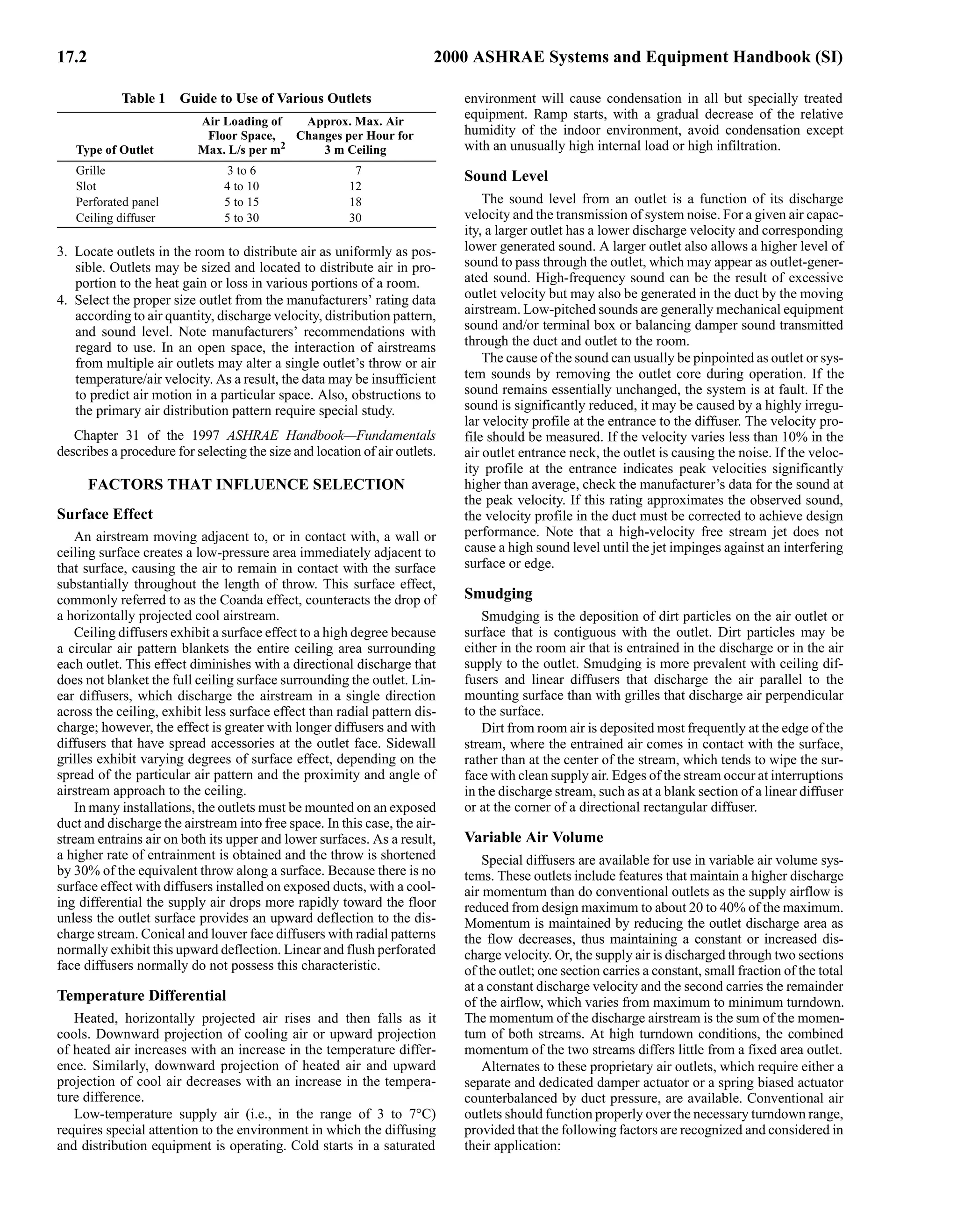


The American Society of Heating, Refrigerating and Air-Conditioning Engineers (ASHRAE) supports research to improve indoor environmental quality and sustainability. ASHRAE members share knowledge and write industry standards. ASHRAE also funds research through donations, enabling them to study new technologies and materials. The ASHRAE Handbook is regularly updated based on member expertise and research findings. It describes HVAC systems, equipment, and components to help designers select and operate efficient and effective solutions.


