Downloaded 17 times
![International Journal of Electronics and Communication Engineering & Technology (IJECET), ISSN 0976
INTERNATIONAL JOURNAL OF ELECTRONICS AND
– 6464(Print), ISSN 0976 – 6472(Online) Volume 3, Issue 1, January- June (2012), © IAEME
COMMUNICATION ENGINEERING & TECHNOLOGY (IJECET)
ISSN 0976 – 6464(Print)
ISSN 0976 – 6472(Online)
Volume 3, Issue 1, January- June (2012), pp. 130-138
IJECET
© IAEME: www.iaeme.com/ijecet.html
Journal Impact Factor (2011): 0.8500 (Calculated by GISI) ©IAEME
www.jifactor.com
FPGA IMPLEMENTATION OF LOW COMPLEXITY
LINEAR PERIODICALLY TIME VARYING FILTER
Sriadibhatla Sridevi, Dr. Ravindra Dhuli and Prof. P. L. H. Varaprasad
ABSTRACT
This paper presents a low complexity architecture for a linear periodically time
varying (LPTV) filter. This architecture is based on multi-input multi-output(MIMO)
representation of LPTV filters. The input signal is divided into blocks and parallel
processing is incorporated, there by considerably reducing the effective input sampling
rate. A single multiplier can be shared for each linear time invariant (LTI) filter in the
representation. Each LTI filter is realized in the transposed direct form filter using
multiplier less multiplication structures based on Binary common bit patterns (BCS). The
proposed structure is simulated, synthesized and implemented on Virtex v50efg256-7
Field Programmable Gate Array (FPGA).
Index Terms: LPTV, MIMO representation, BCS, FPGA
I. INTRODUCTION
LINEAR periodically time varying (LPTV) systems/filters have number of applications
in many fields such as Control systems, Communications, Signal processing and Circuit
modeling [3], [7], [21], [6]. Spread spectrum applications [6], Trans multiplexing [16],
blind channel estimation [18], spectral scrambling [9], temporal scrambling [4], digital
water marking of natural images [12], sample data systems [21] and multi rate filter
banks [19] are the potential applications.
LPTV systems can be expressed as generalization of Linear time invariant (LTI)
systems. If the input for a M-period LPTV system is delayed by M samples, output is also
delayed by the same number of samples. An LPTV system with a period of ’1’ is nothing
but an LTI system [15]. Various equivalent structures for an LPTV filters and their inter
relationships were derived in [14].
130](https://image.slidesharecdn.com/fpgaimplementationoflowcomplexitylinearperiodicallytimevaryingfilter-121125011544-phpapp02/85/Fpga-implementation-of-low-complexity-linear-periodically-time-varying-filter-1-320.jpg)
![International Journal of Electronics and Communication Engineering & Technology (IJECET), ISSN 0976
INTERNATIONAL JOURNAL OF ELECTRONICS AND
– 6464(Print), ISSN 0976 – 6472(Online) Volume 3, Issue 1, January- June (2012), © IAEME
COMMUNICATION ENGINEERING & TECHNOLOGY (IJECET)
ISSN 0976 – 6464(Print)
ISSN 0976 – 6472(Online)
Volume 3, Issue 1, January- June (2012), pp. 130-138
IJECET
© IAEME: www.iaeme.com/ijecet.html
Journal Impact Factor (2011): 0.8500 (Calculated by GISI) ©IAEME
www.jifactor.com
FPGA IMPLEMENTATION OF LOW COMPLEXITY
LINEAR PERIODICALLY TIME VARYING FILTER
Sriadibhatla Sridevi, Dr. Ravindra Dhuli and Prof. P. L. H. Varaprasad
ABSTRACT
This paper presents a low complexity architecture for a linear periodically time
varying (LPTV) filter. This architecture is based on multi-input multi-output(MIMO)
representation of LPTV filters. The input signal is divided into blocks and parallel
processing is incorporated, there by considerably reducing the effective input sampling
rate. A single multiplier can be shared for each linear time invariant (LTI) filter in the
representation. Each LTI filter is realized in the transposed direct form filter using
multiplier less multiplication structures based on Binary common bit patterns (BCS). The
proposed structure is simulated, synthesized and implemented on Virtex v50efg256-7
Field Programmable Gate Array (FPGA).
Index Terms: LPTV, MIMO representation, BCS, FPGA
I. INTRODUCTION
LINEAR periodically time varying (LPTV) systems/filters have number of applications
in many fields such as Control systems, Communications, Signal processing and Circuit
modeling [3], [7], [21], [6]. Spread spectrum applications [6], Trans multiplexing [16],
blind channel estimation [18], spectral scrambling [9], temporal scrambling [4], digital
water marking of natural images [12], sample data systems [21] and multi rate filter
banks [19] are the potential applications.
LPTV systems can be expressed as generalization of Linear time invariant (LTI)
systems. If the input for a M-period LPTV system is delayed by M samples, output is also
delayed by the same number of samples. An LPTV system with a period of ’1’ is nothing
but an LTI system [15]. Various equivalent structures for an LPTV filters and their inter
relationships were derived in [14].
130](https://image.slidesharecdn.com/fpgaimplementationoflowcomplexitylinearperiodicallytimevaryingfilter-121125011544-phpapp02/75/Fpga-implementation-of-low-complexity-linear-periodically-time-varying-filter-1-2048.jpg)
![International Journal of Electronics and Communication Engineering & Technology (IJECET), ISSN 0976
– 6464(Print), ISSN 0976 – 6472(Online) Volume 3, Issue 1, January- June (2012), © IAEME
The relations between multi-input multi-output (MIMO) representation and
various other representations are presented in [15]. Here the authors present a technique
to transform from the LTI MIMO structure to the original single-input/single-output
LPTV difference equation and discusses its implications. The hardware implementation
of the LPTV filters is the area of greater interest now a day. Much of the previous work
concentrated on VLSI implementation of LTI filters. The complexity of LTI filters is
dominated by the complexity of coefficient multipliers. R. I. Hartley proposed that the
common sub expression elimination (CSE) methods based on canonical signed digit
(CSD) coefficients will produce low complexity FIR filter coefficient multipliers [8]. In
[13], the technique in [8] was modified to minimize the number of adder-steps in a
maximal path of decomposed multiplications and thus to improve the speed of operation.
In [10], R. Mahesh and A. P. Vinod proposed the Binary Common Sub expression (BCS)
elimination algorithm. It resulted in improved adder reductions and thus low complexity
FIR filters compared to [8] and [13]. In [20], a method based on the pseudo floating point
method was used to encode the filter coefficients and thus to reduce the complexity of the
filter. Implementation approach for reconfigurable FIR filters has been proposed in [17]
and [11]. Ref [2], [1] have touched on the VLSI implementation of multi rate FIR filter
design.
In the present work we introduce a novel implementation strategy for an LPTV filter
using the MIMO representation. Any given LPTV filter can be viewed as MIMO LTI system.
Thus the analysis of MIMO LTI systems can be directly applied to LPTV systems. If we are
considering an LPTV system of period M, we will divide the input signal into blocks of size M.
We employ parallel processing on this blocks using LTI systems. Hence the effective input
sampling rate reduces by a factor M. After processing the resulting output signals are interlaced
equivalently to perform unblocked. Since there is a considerable reduction in the input sampling
rate, we can employ single multiplier on shared basis for each LTI filter. In the proposed
architecture, multiplication is performed without multipliers using Binary Common Bit patterns
(BCS) based shift and add units, multipliers and adders.
The organization of the paper is as follows. Section II deals with the basics of
LPTV system. Section III explains the proposed LPTV FIR filter design. Simulation and
synthesis results are presented in section IV. Section V concludes the paper.
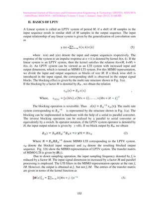
(a) Blocking operator (b) MIMO Representation
Fig. 1 Blocking operator and MIMO representation
131](https://image.slidesharecdn.com/fpgaimplementationoflowcomplexitylinearperiodicallytimevaryingfilter-121125011544-phpapp02/85/Fpga-implementation-of-low-complexity-linear-periodically-time-varying-filter-2-320.jpg)
![International Journal of Electronics and Communication Engineering & Technology (IJECET), ISSN 0976
– 6464(Print), ISSN 0976 – 6472(Online) Volume 3, Issue 1, January- June (2012), © IAEME
This relation an be proved by Fig. 1(a) and Fig. 1(b). Interested reader may refer
[5].To realize an N-tap, M period LPTV system in MIMO representation M2 LTI filters
consisting of N/M taps each are required. There are two advantages in this realization.
First advantage is that, instead of M number of N-tap filters, we can use M2 number of
N/M-tap filters. This facilitates to run all N/M tap filters in parallel which increases the
speed of operation. All the LTI filters can run at a sampling frequency of fs /M, instead of
fs. This is the second advantage. Each N/M tap filters requires N/M coefficient multipliers
normally. But as the rate at which multiplier has to operate is reduced by a factor M, we
can use a single multiplier in time sharing basis for all N/M coefficient multiplications.
Hence the total number of multipliers required for the entire LPTV system is reduced
from M × N to only M and this can considerably reduce the area occupied.
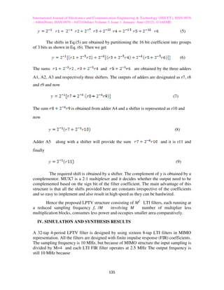
(a) Shift and Adder architecture (b) Multiplication block
III. LOW COMPLEXITY LPTV FIR FILTER DESIGN
An N- tap, M- period LPTV filter can be realized by using M2 LTI filters of N/M taps
each. Each LTI filter in the proposed design is in transposed direct form. In the proposed
design ,the coefficient multiplier of each LTI filter is replaced by a multiplier less
multiplication block based on Binary Common bit patterns (BCS).The novel
multiplication block can be divided into two units. BCS based shift and add unit and
multiplication unit.
A. BCS based Shift and Add Unit
An n-bit binary number in general can form 2n Binary Common Bit patterns. For
example, a 3-bit binary representation can form 8 common bit patterns. They are (000),
(001), (010), (011), (100), (101), (110), (111). The common bit patterns like (001), (010)
and (100) do not require any adder for their implementation as they have a single non
zero bit. The bit pattern (000) does not need an adder or a shifter. Considering x as input
signal, the remaining bit patterns can be expressed as follows
133](https://image.slidesharecdn.com/fpgaimplementationoflowcomplexitylinearperiodicallytimevaryingfilter-121125011544-phpapp02/85/Fpga-implementation-of-low-complexity-linear-periodically-time-varying-filter-4-320.jpg)
![International Journal of Electronics and Communication Engineering & Technology (IJECET), ISSN 0976
– 6464(Print), ISSN 0976 – 6472(Online) Volume 3, Issue 1, January- June (2012), © IAEME
(011) = 2−1x + 2−2x
(101) = x + 2−2x (4)
(110) = x + 2−1x
(111) = x + 2−1x + 2−2x
To realize the above Binary Common Bit patterns, five adders are required.
However, if we perform some simplifications such as 2-1x + 2−2x = 2−1(x + 2−1x) and x+
[2-1x+2-2x ] = x+ 2-1 x+2-2x, then all the BCSs can be realized with a minimum of three
adders . The number of adders required to realize all the possible n-bit common binary bit
patterns is 2n-1-1. The architecture of shift and add unit is shown in Fig. 2(a). All the eight
BCS are fed to the multiplication block.
B . Multiplication Block
The architecture of multiplication block is shown in Fig. 2(b). The coefficient
word length is 16 bits .The filter coefficients are stored in the coefficient memory in sign
magnitude form with most significant bit representing the sign bit. Each 16 bit coefficient
is stored as 17 bit value in coefficient memory. Each row in the memory corresponds to
one coefficient. The coefficient values corresponding to 20 to 2−14 are partitioned into
groups of three bits and they are used as select signals to multiplexers MUX1 to MUX5.
It is easy to note that MUX1 to MUX5 are 8:1 multiplexers as they have three select
lines. The value corresponding to 2−15 forms the select line to a 2:1 multiplexer. Let r1 to
r6 denote the outputs of MUX1 to MUX6 respectively. Then the output is given by
TABLE I MACRO-STATISTICS
TABLE II SYNTHESIS RESULTS
134](https://image.slidesharecdn.com/fpgaimplementationoflowcomplexitylinearperiodicallytimevaryingfilter-121125011544-phpapp02/85/Fpga-implementation-of-low-complexity-linear-periodically-time-varying-filter-5-320.jpg)
![International Journal of Electronics and Communication Engineering & Technology (IJECET), ISSN 0976
– 6464(Print), ISSN 0976 – 6472(Online) Volume 3, Issue 1, January- June (2012), © IAEME
Fig. 3 Simulation results
REFERENCES
[1] K.H. Abed and S.B. Nerurkar. Implementation of a low power decimation filter using
1/3-band iir filter. In Wireless Communications and Networking, 2003. WCNC 2003.
2003 IEEE, volume 1, pages 460–465. IEEE, 2003.
[2] D.C. Andreas. Vlsi implementation of a one-stage 64: 1 fir decimator. In 89th
Convention of the Audio Engineering Society, J. Audio Eng. Soc.(Abstracts), volume 38,
page 872, 1990.
[3] W. Chauvet, B. Cristea, B. Lacaze, D. Roviras, and A. Duverdier. Design of
orthogonal lptv filters: Application to spread spectrum multiple access. In Acoustics,
Speech, and Signal Processing, 2004. Proceedings.(ICASSP’04). IEEE International
Conference on, volume 2, pages ii–645. IEEE, 2004.
[4] W. Chauvet, B. Lacaze, D. Roviras, and A. Duverdier. Spreading properties of
periodic clock changes application to interleavers. Signal Processing, 88(2):221–235,
2008.
[5] Ravindra Dhuli and Brajesh Lall, Generalized poly phase identity. In the proceedings
of INDICON 09,DAIICT,Gandhinagar,India,December 2009.
[6] A. Duverdier and B. Lacaze. Transmission of two users by means of periodic clock
changes. In Acoustics, Speech and Signal Processing, 1998. Proceedings of the 1998
IEEE International Conference on, volume 3, pages 1825–1828. IEEE, 1998.
137](https://image.slidesharecdn.com/fpgaimplementationoflowcomplexitylinearperiodicallytimevaryingfilter-121125011544-phpapp02/85/Fpga-implementation-of-low-complexity-linear-periodically-time-varying-filter-8-320.jpg)
![International Journal of Electronics and Communication Engineering & Technology (IJECET), ISSN 0976
– 6464(Print), ISSN 0976 – 6472(Online) Volume 3, Issue 1, January- June (2012), © IAEME
[7] G. Gelli and F. Verde. Blind fsr-lptv equalization and interference rejection.
Communications, IEEE Transactions on, 51(2):145–150, 2003.
[8] R.I. Hartley. Subexpression sharing in filters using canonic signed digit multipliers.
Circuits and Systems II: Analog and Digital Signal Processing, IEEE Transactions on,
43(10):677–688, 1996.
[9] R. Ishii and M. Kakishita. A design method for a periodically time-varying digital
filter for spectrum scrambling. Acoustics, Speech and Signal Processing, IEEE
Transactions on, 38(7):1219–1222, 1990.
[10] R. Mahesh and AP Vinod. A new common subexpression elimination algorithm for
realizing low-complexity higher order digital filters. Computer-Aided Design of
Integrated Circuits and Systems, IEEE Transactions on, 27(2):217–229, 2008.
[11] R. Mahesh and AP Vinod. New reconfigurable architectures for implementing fir
filters with low complexity. Computer-Aided Design of Integrated Circuits and Systems,
IEEE Transactions on, 29(2):275–288, 2010.
[12] V. Martin, M. Chabert, and B. Lacaze. Digital watermarking of natural images based
on lptv filters. In Acoustics, Speech and Signal Processing, 2007. ICASSP 2007. IEEE
International Conference on, volume 2, pages II–197. IEEE, 2007.
[13] M. Mart´ınez-Peir´o, E.I. Boemo, and L. Wanhammar. Design of high-speed
multiplierless filters using a nonrecursive signed common subexpression algorithm.
Circuits and Systems II: Analog and Digital Signal Processing, IEEE Transactions on,
49(3):196–203, 2002.
[14] D. McLernon. One-dimensional linear periodically time-varying structures:
derivations, interrelationships and properties. In Vision, Image and Signal Processing,
IEE Proceedings-, volume 146, pages 245–252. IET, 1999.
[15] DC McLernon. Relationship between an lptv system and the equivalent lti mimo
structure. In Vision, Image and Signal Processing, IEE Proceedings-, volume 150, pages
133–141. IET, 2003.
[16] J.S. Prater and C.M. Loeffler. Analysis and design of periodically time-varying iir
filters, with applications to transmultiplexing. Signal Processing, IEEE Transactions on,
40(11):2715–2725, 1992.
[17] T. Solla and O. Vainio. Comparison of programmable fir filter architectures for low
power. In Solid-State Circuits Conference, 2002. ESSCIRC 2002. Proceedings of the
28th European, pages 759–762. IEEE, 2002.
[18] M.K. Tsatsanis and G.B. Giannakis. Transmitter induced cyclostationarity for blind
channel equalization. Signal Processing, IEEE Transactions on, 45(7):1785–1794, 1997.
[19] P.P. Vaidyanathan. Multirate systems and filter banks. Pearson Education India,
1993.
[20] AP Vinod and E.M.K. Lai. Low power and high-speed implementation of fir filters
for software defined radio receivers. Wireless Communications, IEEE Transactions on,
5(7):1669–1675, 2006.
[21] J. Wang, T. Chen, and B. Huang. Multirate sampled-data systems: computing fast-
rate models. Journal of process control, 14(1):79–88, 2004.
138](https://image.slidesharecdn.com/fpgaimplementationoflowcomplexitylinearperiodicallytimevaryingfilter-121125011544-phpapp02/85/Fpga-implementation-of-low-complexity-linear-periodically-time-varying-filter-9-320.jpg)

This document summarizes a research paper that proposes a low complexity architecture for implementing linear periodically time-varying (LPTV) filters using field programmable gate arrays (FPGAs). The architecture is based on representing an LPTV filter as a multi-input multi-output (MIMO) system of linear time-invariant (LTI) filters. It divides the input signal into blocks and processes them in parallel using LTI filters, reducing the effective input sampling rate. A single multiplier can be shared among the LTI filters. Each LTI filter is realized using multiplier-less multiplication structures based on binary common bit patterns to reduce complexity. The proposed architecture is simulated, synthesized and implemented on an FPGA to