This document provides an overview of foundations, including:
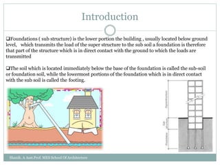
1. It defines foundations and their functions of transmitting loads from buildings to soil.
2. It describes different types of shallow foundations like spread, combined, strap, and raft foundations. It also describes different types of deep foundations like pile, pier, and well foundations.
3. It discusses foundation loads, bearing capacity of soil, methods of testing bearing capacity like plate load tests and penetration tests, and factors for selecting foundations based on soil conditions and building loads.