This document summarizes a paper on the design of machine foundations and the effects of earthquakes. It discusses the need for improved interaction between foundation designers and machine manufacturers to ensure better machine performance. It describes design methodologies and modeling approaches for machine foundations subjected to dynamic loads. Specifically, it recommends using finite element analysis with caution, discusses vibration isolation techniques, and touches on modeling and analyzing the effects of earthquakes on machine foundations.
RELIABILITY OF MECHANICAL SYSTEM OF SYSTEMScscpconf
In this paper, we present a new methodology about reliability of systems of systems. We present
also an example which combines the information transformation in complex systems and virtual
design of this system based on finite element analysis. This example is help to balance the
performances and the costs in complex system, or provide the optimal solution in manufacturing
design. It can also update the existing design of component by changing the new design of this
component.
This document provides an introduction to machine foundation design, which involves structural dynamics, structural engineering, and geotechnical engineering. It discusses the differences between static and dynamic analysis, and covers fundamental concepts in vibration theory like natural frequency, damping, and resonance that are important for machine foundation design. Harmonic motion is described as the simplest form of vibration induced by machines. Different types of vibrating machines are discussed, including reciprocating machines, rotary machines, and impact machines. Machine foundations must be designed to withstand the vibratory loads from machine operation while preventing excessive vibration that could damage the machine or foundation.
This document analyzes methods to reduce vibrations transmitted from machines to foundations. It examines a frame foundation model supported by springs, hard rock basalt layers, and soft rubber layers beneath the foundation. Dynamic analysis was conducted to determine the foundation's natural frequency and plot transmissibility curves. Results show that a soft rubber layer is most effective at isolating vibrations, with support reaction decreasing significantly as stiffness increases, indicating better vibration control compared to spring or hard rock basalt supports. The document concludes with recommendations for machine foundation design to minimize vibration transfer.
This document summarizes research on designing the column structure of a Horizontal Machining Center (HMC) to withstand vibration during operation. Three column structure concepts were modeled and analyzed in CREO and ANSYS to determine their natural frequencies and deformation under load. Modal analysis found Concept 1 had the highest natural frequency, lowest weight, and least deformation, indicating it would provide the most stability. Cutting force calculations for milling and drilling operations were also presented to estimate the loads the column would experience from dynamic machine components like the spindle motor. A pre-stressed analysis was proposed to validate the column's performance under the cutting forces generated during heavy machining processes.
IRJET- Seismic Evolution of Soft Storeyed Structures When Exposed to Earth Qu...IRJET Journal
This document summarizes a study on strengthening soft-story buildings to improve their seismic performance. Soft-story buildings, which have open or weaker first floors, perform poorly in earthquakes. The study models an 8-story reinforced concrete building under different structural configurations, including bare frame, infill masonry walls, shear walls, and bracing systems. Nonlinear static pushover analysis is used to evaluate the capacity and seismic response of each model. The results show that including infill walls, shear walls or bracing systems increases the building's lateral stiffness and decreases its fundamental natural period compared to the bare frame model. Strengthening the ground floor improves the seismic resistance of soft-story buildings.
IRJET- Structural Analysis and Optimization of ‘C’ Frame of Mechanical PressIRJET Journal
This document summarizes a study that analyzed and optimized the structural design of the 'C' frame component of a 100-ton mechanical press machine. The original C-frame design was modeled and analyzed using finite element analysis software to determine stress levels and weight. Various optimization techniques were then applied, including changing dimensions, materials, or both, to minimize weight while maintaining structural integrity. The optimal design was found to use mild steel with dimensions of 2100mm height, 250mm width and 80mm thickness, reducing the C-frame weight by 363kg (68% material savings) while keeping stress levels below allowable limits. This optimized design could lower material costs for the press machine.
The document discusses Anthropic's Simulation and ANSYS software capabilities. It introduces ANSYS, describing its capabilities for linear static stress analysis, vibration analysis, and thermal analysis. It outlines the basic steps for performing a complete ANSYS analysis, including preprocessing tasks like geometric modeling, applying loads and boundary conditions, element selection, and material property definition before solving and viewing results.
Seismic Evolution of Soft Storeyed Buildings when Subjected to Real Time Eart...IRJET Journal
This document discusses seismic evaluation of soft-storey buildings and methods to strengthen them. It begins with an abstract stating that buildings are often designed without considering the structural effects of masonry infill walls. During earthquakes, buildings with open ground floors (soft-storeys) perform poorly as the ground floor columns cannot provide adequate shear resistance. The document then evaluates 8 building models with different lateral load resisting systems - bare frame, masonry infill, shear walls, bracing - using linear static, linear dynamic and nonlinear static (pushover) analysis methods. It provides the design data, load calculations, time period calculations, and equivalent static analysis as per Indian codes for the models. Distribution of lateral forces is also shown
1. The document describes the author's 6-week training experience using ANSYS software to conduct various engineering simulations including static structural, explicit dynamics, fatigue, modal, steady-state thermal, transient thermal, and fluid flow analyses.
2. Several examples are provided for each type of analysis conducted in ANSYS including the analysis of a rim, bullet impact, connecting rod, airplane, cylindrical fins, piston head, and natural convection flow in a tube.
3. For each example, the author details the geometry, materials, meshing, boundary conditions, and results of the simulations performed in ANSYS to gain experience with the software.
An Optimization of pallet weight is an key point to be considered for lean manufacturing,cost reduction & effective operations. An effort for optimization of pallets has been carried out by many researchers using various methods considering static& dynamic loading conditions.
IRJET- Pushover Analysis on Reinforced Concrete Building using ETABSIRJET Journal
This document presents the results of a pushover analysis conducted on a 10-story reinforced concrete building modelled in ETABS to investigate the impact of using cracked versus uncracked section properties. Three cases were analyzed using different moment of inertia values to represent uncracked (1.0), partially cracked (0.7) and fully cracked (0.35) sections. The pushover curves showed that using cracked section properties resulted in lower base shear and displacement capacity compared to the uncracked model. The cracked section models more accurately represent the actual response and capacity of existing buildings that have developed cracks due to service loads. Accounting for cracked section properties is important for performance-based design.
This document summarizes a study that analyzed the stresses in a flywheel design using finite element analysis. It describes modeling a Maruti 800 flywheel in CATIA and analyzing it in ANSYS. Two materials were considered - gray cast iron and S-glass epoxy. The flywheel was meshed and appropriate boundary conditions were applied. The results found the maximum normal stress to be 44.07 MPa for gray cast iron and 11.54 MPa for S-glass epoxy. The study demonstrated using FEA to optimize flywheel design and select suitable materials.
Finite Element Analysis of Pedal Power Hub dynamomsejjournal
The Hub Dynamos are built for electricity generation form the bicycle motion and they are in light weight
and have low frictional resistance. However they are still subjected to normal bicycle loading such as
bicycle frame, rider weight, acceleration, braking and cornering forces. The challenge is to develop a
lightweight hub housing and hub axle that can safely withstand the required loads. The present paper deals
with designing a Hub dynamo assembly using Solid Works Office Premium software. The assembly
comprises of the Hub shell, hub axle, internal gear assembly, armature, and fasters. Static structural
analysis was done using SW simulation software. The plots for equivalent von-misesstress plot, total
deformation plot were obtained and the design was continuously optimized till a safe design was
obtained.Maximum distortion energy theory was used for the analysis. The material assignment is as
follows: hub assembly- Aluminum Alloys 356.0 T-6, hub axle- ASTM A36 Steel and Gear Assembly
Bracket- Alloy Steel (SS).
This document provides an overview of hazard maps and fragility maps. It discusses how fragility maps are constructed using fragility curves, which relate the probability of different damage states to the demand placed on a structure. Fragility curves are developed for different building types using numerical modeling and accounting for uncertainty. Shake maps are also discussed, which map ground shaking from earthquakes using ground motion prediction equations and sensor data. A case study on developing fragility maps for building types in Honduras is presented to demonstrate the process.
IRJET- Comparative Study & Seismic Anyalysis of Regular and Irregular Geometr...IRJET Journal
This study compares the seismic analysis of regular and irregular high-rise buildings in different seismic zones of India. Finite element software will be used to model and analyze a 10-story regular and irregular building subjected to different seismic zones. Results like deflections, axial forces, and moments will be compared to understand how seismic zone and building geometry affect structural response. The aim is to help improve earthquake-resistant design of high-rise buildings.
Design, analysis and development of special purpose machine to carry heavy lo...eSAT Journals
Abstract
In the olden days very complicated thing is in the industry is to carry heavy loaded components and lifting from one place to another place, human effort needs lots of energy and it takes more time for same work, there are many huge and large amount of load lifting machine available, in that first started with gantry hoist and gantry cranes with which they carry heavy loads from one place to other, it works so far by the time but it can operate only in open place, in small scale industries it can’t work, during the period the need is new machine which works in small scale industries with good time, the changing the generation with the new technology industries are planned to develop the special purpose machine which is used to lift the heavy loads. Structural analysis of the “Gantry Structure” has been carried out to find the mechanical response of the structure, subjected to applied loads and boundary conditions. The results include deformed shape of the structure, displacements at required locations. Modal analysis done for checking the model, Gravity Loading Applied for different position and checked for the deformation of Solid Beam for different position. Optimization is done to reduce the cost of the structure. The response of the structure got by structural analysis using MSC Nastran.
Keywords: Gantry, Types of gantry, Structural analysis, optimization, modal analysis, HyperMesh, NASTRAN.
IRJET- Effect of Vertical Irregularities in R.C Frame Structures on Accuracy ...IRJET Journal
This document discusses the effects of vertical irregularities in reinforced concrete frame structures on the accuracy of nonlinear static pushover analysis. It presents the results of nonlinear static pushover analysis and nonlinear time history analysis on 15 vertically irregular frame models with varying heights and types of irregularities. The models are analyzed using the SAP2000 software. The results show that pushover analysis reasonably estimates the seismic demands of vertically irregular buildings when compared to time history analysis, and the pushover results have good correlation with selected ground motion records.
IRJET-Optimization of Geometrical Parameters of Single Point Cutting Tool to ...IRJET Journal
The document discusses optimizing the geometrical parameters of a single point cutting tool to reduce stress and vibration during turning operations. Modal and harmonic analyses were performed to determine the tool's natural frequency range of 11384Hz to 45322Hz. Optimization found the minimum stress and vibration occurred with a horizontal and vertical cross-sectional dimension of 18.2mm, a back rack angle of 10.88°, side rack angle of 10.88°, end relief angle of 9.06°, end cutting angle of 27.2°, and side cutting edge angle of 13.6°. The optimal parameters can help reduce tool wear and extend the life of single point cutting tools.
This document presents a study that proposes and experimentally validates a robust control strategy for industrial motion control using an Extended State Observer (ESO). The control strategy is designed to enforce robustness without requiring information about uncertainties and disturbances in the system. The ESO is used to estimate the lumped uncertainties and disturbances, and the estimated values are used in the control law to guarantee robust performance. The effectiveness of the proposed strategy is experimentally tested on an industry-standard hardware testbed for various trajectory tracking performances under different induced uncertainties like backlash, friction, and disturbances.
Non linear analysis and optimization of flywheelIRJET Journal
This document discusses the non-linear finite element analysis of a flywheel made of different materials. It begins with an introduction to flywheels and the motivation for performing non-linear analysis. The flywheel model is created in SolidWorks and meshed. Non-linear static analysis is performed in ANSYS considering step loading and centrifugal forces. Various parameters like deformation, stress, and factor of safety are analyzed and compared for aluminum alloy and cast iron flywheel models. Shape optimization is also performed to reduce the flywheel mass by 20%. Experimental validation of deflection values matches well with FEA results, with error within 3-4%. Aluminum alloy is found to have lower stresses compared to cast iron, making it better
IRJET - Structural Optimisation of Upper Control ARM for Double Wishbone ...IRJET Journal
This document discusses the structural optimization of the upper control arm for a double wishbone suspension system. It aims to reduce the weight of the upper control arm by 10-12% to reduce costs while maintaining structural integrity. The document outlines the existing design, theoretical load calculations, and finite element analysis using ANSYS. Through iterative modeling and analysis, the optimized design was able to reduce the weight of the upper control arm by 6.9% while keeping stresses and deformations within safe limits.
The document describes the design and development of an attachment for a universal testing machine (UTM) to enable torsion testing. The attachment allows the UTM to determine the torsional strength and stiffness of materials by applying a twisting motion. It consists of a base plate and two chucks, with one chuck fixed and the other rotating due to steel wires connected to the UTM head. Calculations were done to design the attachment's dimensions. Torsion tests on rods showed modulus of rigidity values that matched standard results, demonstrating the feasibility of the attachment for expanding the UTM's testing capabilities.
The document summarizes the structural analysis of a culvert using finite element analysis software ANSYS. It describes the steps taken which include defining the material properties of low-carbon steel, applying appropriate loading and boundary conditions, generating a mesh, and analyzing the results to find maximum deformation and Von Mises stress. The maximum deformation occurs in the horizontal direction while the stress is concentrated at the arc of the structure. Reinforcement of the arc is recommended to improve the design.
Influence of Concrete and Steel Outrigger and Belt Truss in High Rise Moment ...IRJET Journal
1. The document analyzes 7 models of a 44-story reinforced concrete frame building with different outrigger and belt truss configurations to evaluate their effectiveness in reducing lateral displacement, storey drifts, base shear, and fundamental time periods under wind and earthquake loads.
2. Analysis found that a model with X-braced outriggers was most effective at reducing top storey displacement by 29.21% and maximum story drift by 26.64% compared to the bare frame model without outriggers. A model with a belt truss was also effective, reducing displacement by 34.57% and drift by 30.75%.
3. Steel outriggers provided the least benefit, reducing displacement by only
This document discusses engineering analysis software packages used in CAD. It introduces common types of engineering analysis like stress-strain calculations, heat transfer analysis, and dynamic simulation. It then describes examples of engineering analysis software in common use, including mass property analysis, interference checking, tolerance analysis, finite element analysis, kinematic and dynamic analysis, and discrete-event simulation. These software packages are used to perform complex engineering computations and simulations that aid the design process.
IRJET-Analysis of Beam Column Joint using Finite Element Method – Comparative...IRJET Journal
This document presents an analysis of beam-column joints in reinforced concrete structures using various methods, including stiffness method, flexibility method, finite element analysis using ANSYS, and strain energy method. The study analyzed an end joint and intermediate joint of a reinforced concrete beam-column system. The results showed that finite element analysis yielded the lowest values for bending moment, shear force, and stresses compared to the other methods. Therefore, finite element analysis can provide a more realistic design of beam-column joints compared to other analysis methods.
This document provides an overview of machine design. It defines machine design as designing machine elements and arranging them to obtain useful work. It discusses different types of design such as adaptive, developmental, and new design. It outlines key factors to consider in machine design like materials, forces, size, manufacturability, reliability, and cost. The goal of machine design is to safely transmit forces while allowing the machine to perform its task.
Dynamic analysis of machine foundation: when a static force cannot give the f...Gary Yung
This paper presents various design approaches for machine foundations from a rule of thumb static design to a comprehensive dynamic analysis and discusses their design limitations.
Dynamic Analysis of Foundation Supporting Rotary MachineIJERA Editor
With the advancement of technology in the field of industry, high speed machinery has been developed. As the speed of machinery has increased, vibrations also increased. Machines transmit vibrations to the structure supporting them. Hence, it is important to design and develop such structure which sustains the vibrations of machinery. Hence, in this study it has been aimed to execute the study on foundations supporting rotary type of machine like blower. In this paper, the most important parameters like frequency and amplitude are considered while execution of analysis of machine foundation supporting blower type machine. This paper shows, better interface between foundation designer and machine manufacturer for better performance of machine. The design aids/approaches for foundation design is also described in this paper and an attempt has been made to study the dynamic behaviour of a foundation structure for blower type machine subjected to forces due to operation of blower machine. Two different types of foundations for Rotary type Machine that is Blower have been studied in this paper
Finite Element Based Analysis of Rotating Robot PedestalIRJET Journal
The document describes performing a finite element analysis on the pedestal structure that supports two rotating robots. It outlines creating a CAD model of the pedestal in ANSYS, applying boundary conditions like forces and moments from the robot specifications, and analyzing the structure to determine equivalent stress and total deformation to validate that the design is safe and stable under the expected loads. The analysis found the maximum stress of 216 MPa and deformation of 1.33 mm when applying the worst-case load combinations, and modifications to the bolt size reduced the stress below the allowable limit of 150 MPa.
On account of cutting gadget holder preoccupation, cutting force affects the
dimensional precision. The troublesome of equipment holder redirection is attempted
routinely in a course of action of building surface things, and to accomplish this point
uninvolved strategy can be utilized. In this unassuming work, a refreshed hypothetical
momentous cutting force appear for end getting ready is open, utilizing confined part
approach. The model be committed to variable data sources, pick the kind of the end
procedure holder, in the event that it is straight or discontinuous. The cutting
parameters are given for getting a perfect preparing instrument redirection dispersing
and rehash an area examination. The expansion results demonstrate that the
instrument evading impacts the dimensional precision of the completed part. The
essential structures of pulled back technique for distraction mask of mechanical
frameworks are quickly exhibited. It depends upon the hypothesis of dynamic
redirection. For handling forces and gadget holder redirection, two sorts of instability
show yields are shown identifying with cutting force parameters
DESIGN AND DEVELOPMENT OF MACHINE FAULT SIMULATOR (MFS) FOR FAULT DIAGNOSISijmech
Recent years have seen the rise of vibration problems associated with structures, which are more delicate
and intricate, machines that are faster, more complex and production process that are automated and
interlinked. The occurred problems are directly related to demands of lower investment, running and
maintenance cost in incidence with the requirement of increase productivity and efficiency. This work
developed aMachine Fault Simulator (MFS),whichis the most comprehensive laboratory scale machine on
the market for performing rotor dynamics experiments.Also, it helps in learning vibration signature of the
most common machinery faults in a controlled manner without compromising your quality production/
profits. The bench top system has a spacious modular design featuring versatility, operational simplicity
and robustness in depth studies of a variety of faults can be conducted using over many applications. Some
examples are rolling element bearing defects, Gear defect, belt and pulley defect, motor bearing defect.
Structural damage mitigation in discrete structures using multiple actuatorsIAEME Publication
This document summarizes research on using actuators and feedback controllers to mitigate structural damage growth in discrete structures. It discusses using state and state derivative feedback controllers to assign undamaged eigenvalues and eigenvectors to a damaged structure, reducing vibration at damaged areas. It then illustrates applying this technique to a spring-mass-damper system with a known damaged spring, using eigenvector options to determine actuator loads that reduce vibration at the damaged spring. The goal is to extend the life of damaged structures undergoing dynamic loads using active structural control methods.
IRJET- Stress Concentration of Plate with Rectangular CutoutIRJET Journal
This document discusses a study that analyzes stress concentration in plates with various shaped cutouts using finite element analysis software (ANSYS). The study compares stress concentration factors around circular, square, and rectangular cutouts in metallic plates made of materials like mild steel and aluminum. Experimental tensile tests are also conducted on plates with different cutout shapes and loaded in one direction. Results from the finite element analysis are validated by comparing with experimental test results, finding them to be relatively similar. The stress concentration is highest for plates with cutouts that have more oriented geometries compared to a baseline. Orientation is identified as an important factor in reducing stress concentration.
IRJET- Seismic Time History Performance of Conventional Multi-Outriggers with...IRJET Journal
This document summarizes a study that analyzed the seismic performance of different configurations of outrigger systems in high-rise buildings using time history analysis. Five 35-story building models were analyzed: 1) bare frame, 2) two outriggers, 3) two outriggers with belt truss, 4) three outriggers, and 5) two outriggers with mega columns. The models were subjected to time history analyses using earthquake records. Results showed that using multiple outriggers and mega columns reduced top story displacements, inter-story drifts, and building period compared to the bare frame model, with two outriggers with mega columns performing the best. Outriggers significantly reduced drift at outrigger levels,
Test platform for electronic control units of high-performance safety-critica...IJECEIAES
In this paper we are mostly concerned with the problem of testing electronic control units of synchronized electric power actuators. This task is particularly complex for safety critical applications, where it is crucial that the control system properly reacts in response to the faults that are hard to reproduce and verify. A cost-effective flexible and reconfigurable test platform is proposed, discussing its architecture and implementation. The proposed system facilitates the phase of definition and development of the electronic control unit, allowing the interfacing towards both hydraulic and electromechanical actuators, and having a high flexibility as regards the I/O signals. Some results, obtained during the laboratory test activity, are also presented.
This thesis examines the design of dynamically loaded foundations for pumps and compressors. It provides background on different machine and foundation types that must account for dynamic loads. Key design criteria are avoiding resonance, limiting vibration amplitudes, and restricting settlement. An Excel file is created to calculate foundation parameters for rotary and reciprocating machines based on machine properties, soil properties, and theoretical models representing different vibration modes as spring-mass-damper systems. The resulting file allows checking foundation compliance with criteria for dynamically loaded foundations.
This document presents a literature review and overview of machine foundation design for a civil engineering course project. It discusses the increasing vibrations caused by advancing machinery technology. Various types of machine foundations are described, including block, box, spring mounted block, combined block, tabletop, tabletop with isolator, inertia block in structure, and pile supported foundations. Foundation design criteria aim to limit motion amplitudes. Soil exploration is important to understand foundation response to dynamic loads. Depth of site exploration should be sufficient. In conclusion, thermal power plants require extensive foundation studies due to heavy equipment, and foundation issues cause about 19% of equipment problems annually.
Design and Analysis of Mechanism for Dynamic Characterization of Power Transm...iosrjce
Power transmission systems are being widely used for transmission of power between two members.
Once a particular transmission system is realized it needs to be qualified before its course of application. As
part of this intended torque of the transmission systems needs to be measured and tested. Conventional means of
dynamic characterization of power transmission system has got the demerit of energy consumption to a greater
extent. Because of this more effort is to be put in terms of power for the sake of testing the intended system.
Great need exists for a system which consumes less or ideally no energy while performing test. This project
aims at evolution of a novel technique for evaluating the torque transmitting capability of power transmission
systems without consuming more energy. To start with all the subsystems of the proposed design will be
identified and each of them will be designed for getting their dimensions. Then these dimensional models will be
transformed to solid model of the assembled configuration using 3D CAD software. Functional load which will
be experienced by this design will be assessed and structural analysis will be carried out against these loads
using Finite Element Method (FEM) in commercial FEA software i.e. ANSYS
The document describes the design and analysis of a mechanism to dynamically characterize power transmission systems without consuming significant energy. It involves using an electro-mechanical clutch connected to a motor via pulleys of different sizes to measure the torque transmitting capability of a transmission system by gradually increasing the load torque until slip occurs. Structural analysis using FEA found the design to be safe with a factor of safety above the minimum required.
Proportional integral derivative controller based on ant colony optimization...IJECEIAES
Flexible plate structure provides many benefits as compared to their rigid counterparts including lower energy consumption, effective, lightweight, and quick response. However, the vibration easily affects the flexible plate structure resulting in structural damage. This study introduces the modelling of a flexible plate structure based on a system identification technique known as ant colony optimization (ACO) algorithm for vibration control. Firstly, the input-output vibration data that represent the actual structure of flexible plate was achieved from the experiment. Next, the acquired vibration data was used to develop a dynamic model of the flexible plate structure. The performances of the ACO algorithm were assess based on mean squared error (MSE), pole-zero plot and correlation test in order to get a precise and reliable outcome. The results show that ACO algorithm achieved the minimum MSE which was 6.7613 × 10⁻⁶ , high stability of pole-zero plot and excellent correlation test. Subsequently, the best model of ACO was chosen to create controller based on an active vibration control technique. It was noticed that the controller managed to obtain a 6.19 dB reduction at the first mode vibration in which the percentage of attenuation of the controller was 10.63% for sinusoidal disturbances and 9.64% for multiple sinusoidal disturbances.
IRJET- Base Isolation and Damping Sytems for Earthquake ResistanceIRJET Journal
This document discusses various damping systems and base isolation techniques that can be used to improve the earthquake resistance of buildings. It summarizes the types of damping systems, including viscous dampers, tuned mass dampers, base isolation, active damping and semi-active damping. The document compares the performance of buildings with base isolation and damping systems to fixed base buildings through analytical models. It finds that base isolated buildings and those with damping systems experience significantly reduced displacements compared to fixed base buildings. Finally, the document discusses the use of viscous damping systems specifically for high-rise buildings and their advantages over other techniques.
This document summarizes a research paper that proposes a computer-aided mass balancing method for rotary fixtures on CNC machines. The method uses CAD software to divide the fixture into four quadrants and calculate the mass properties of each quadrant. It then analyzes the mass distribution to determine any imbalances and calculates the necessary counterweights to balance the fixture. This approach allows imbalances to be predicted and addressed during the design phase before manufacturing, which can save costs and improve productivity compared to traditional post-manufacturing balancing methods. The paper presents this proposed computer-aided mass balancing method as applied to the specific case of designing a rotary fixture for machining a TEE body component on a CNC turning center.
This document defines machine design and its considerations. Machine design is using scientific principles and imagination to describe a machine to perform tasks efficiently. The design specifies materials, sizes, and arrangements of mechanical elements. The design aims to optimize parameters, reduce costs, prevent failures, and satisfy prescribed tasks. Computer systems assist in design creation, modification, analysis and optimization. Proper design improves user experience and reduces size/weight while meeting strength, deflection, probability of failure, safety, cost, and other standards.
Automation of Fixtures Using Hydraulic Power Pack for a Bogie UnderframeIOSR Journals
In this era of automation technologies manufacturing sectors have placed very high demands on fast and reliable production methods. This work is the evaluation & analysis of the existing clamping system. The current system uses manual clamping of fixtures for holding the work piece in the proper position while welding process is being done on the part. The evaluated system uses hydraulic vertical swing clamps for holding the work piece driven by hydraulic power pack. Thus the new system achieves automatic and simultaneous clamping of fixtures.
Quasi-Static Evaluation of a Modular and Reconfigurable Manufacturing CellHillary Green
This document presents a novel modular and reconfigurable manufacturing cell (MRMC) system that aims to provide flexible manufacturing capabilities. Some key points:
- The MRMC system consists of modular manipulation hardware and software that can be quickly configured and reconfigured for different assembly and packaging applications.
- It uses a unique interconnect design to allow mechanical and electrical connection between modules. Distributed intelligence and self-locating software enables automatic configuration.
- Analytical evaluation of precision shows the MRMC maintains necessary accuracy and repeatability for tasks like pick-and-place despite reconfiguration.
- The goal is to offer a low-cost, low-risk solution for prototyping and low-volume manufacturing through
Optimization of vehicle suspension system using genetic algorithmIAEME Publication
This document describes using a genetic algorithm to optimize the parameters of a vehicle suspension system. A quarter-car model with 5 parameters is developed in Matlab and Simulink. The objective is to minimize sprung mass acceleration. A genetic algorithm is run for 51 generations to optimize the parameters. The optimized parameters found are reported, and plots show the genetic algorithm converged on optimal solutions. The optimized suspension model response matches the goal of minimizing sprung mass acceleration compared to initial arbitrary parameter values.
Introduction to AI for Nonprofits with Tapp NetworkTechSoup
Dive into the world of AI! Experts Jon Hill and Tareq Monaur will guide you through AI's role in enhancing nonprofit websites and basic marketing strategies, making it easy to understand and apply.
Macroeconomics- Movie Location
This will be used as part of your Personal Professional Portfolio once graded.
Objective:
Prepare a presentation or a paper using research, basic comparative analysis, data organization and application of economic information. You will make an informed assessment of an economic climate outside of the United States to accomplish an entertainment industry objective.
it describes the bony anatomy including the femoral head , acetabulum, labrum . also discusses the capsule , ligaments . muscle that act on the hip joint and the range of motion are outlined. factors affecting hip joint stability and weight transmission through the joint are summarized.
This presentation was provided by Steph Pollock of The American Psychological Association’s Journals Program, and Damita Snow, of The American Society of Civil Engineers (ASCE), for the initial session of NISO's 2024 Training Series "DEIA in the Scholarly Landscape." Session One: 'Setting Expectations: a DEIA Primer,' was held June 6, 2024.
How to Add Chatter in the odoo 17 ERP ModuleCeline George
In Odoo, the chatter is like a chat tool that helps you work together on records. You can leave notes and track things, making it easier to talk with your team and partners. Inside chatter, all communication history, activity, and changes will be displayed.
The simplified electron and muon model, Oscillating Spacetime: The Foundation...RitikBhardwaj56
Discover the Simplified Electron and Muon Model: A New Wave-Based Approach to Understanding Particles delves into a groundbreaking theory that presents electrons and muons as rotating soliton waves within oscillating spacetime. Geared towards students, researchers, and science buffs, this book breaks down complex ideas into simple explanations. It covers topics such as electron waves, temporal dynamics, and the implications of this model on particle physics. With clear illustrations and easy-to-follow explanations, readers will gain a new outlook on the universe's fundamental nature.
বাংলাদেশের অর্থনৈতিক সমীক্ষা ২০২৪ [Bangladesh Economic Review 2024 Bangla.pdf] কম্পিউটার , ট্যাব ও স্মার্ট ফোন ভার্সন সহ সম্পূর্ণ বাংলা ই-বুক বা pdf বই " সুচিপত্র ...বুকমার্ক মেনু 🔖 ও হাইপার লিংক মেনু 📝👆 যুক্ত ..
আমাদের সবার জন্য খুব খুব গুরুত্বপূর্ণ একটি বই ..বিসিএস, ব্যাংক, ইউনিভার্সিটি ভর্তি ও যে কোন প্রতিযোগিতা মূলক পরীক্ষার জন্য এর খুব ইম্পরট্যান্ট একটি বিষয় ...তাছাড়া বাংলাদেশের সাম্প্রতিক যে কোন ডাটা বা তথ্য এই বইতে পাবেন ...
তাই একজন নাগরিক হিসাবে এই তথ্য গুলো আপনার জানা প্রয়োজন ...।
বিসিএস ও ব্যাংক এর লিখিত পরীক্ষা ...+এছাড়া মাধ্যমিক ও উচ্চমাধ্যমিকের স্টুডেন্টদের জন্য অনেক কাজে আসবে ...
How to Fix the Import Error in the Odoo 17Celine George
An import error occurs when a program fails to import a module or library, disrupting its execution. In languages like Python, this issue arises when the specified module cannot be found or accessed, hindering the program's functionality. Resolving import errors is crucial for maintaining smooth software operation and uninterrupted development processes.
How to Build a Module in Odoo 17 Using the Scaffold MethodCeline George
Odoo provides an option for creating a module by using a single line command. By using this command the user can make a whole structure of a module. It is very easy for a beginner to make a module. There is no need to make each file manually. This slide will show how to create a module using the scaffold method.
Strategies for Effective Upskilling is a presentation by Chinwendu Peace in a Your Skill Boost Masterclass organisation by the Excellence Foundation for South Sudan on 08th and 09th June 2024 from 1 PM to 3 PM on each day.
Thinking of getting a dog? Be aware that breeds like Pit Bulls, Rottweilers, and German Shepherds can be loyal and dangerous. Proper training and socialization are crucial to preventing aggressive behaviors. Ensure safety by understanding their needs and always supervising interactions. Stay safe, and enjoy your furry friends!
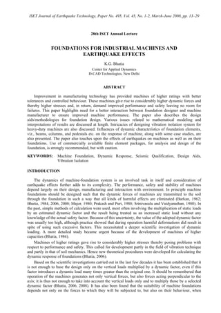
1. ISET Journal of Earthquake Technology, Paper No. 495, Vol. 45, No. 1-2, March-June 2008, pp. 13–29
28th ISET Annual Lecture
FOUNDATIONS FOR INDUSTRIAL MACHINES AND
EARTHQUAKE EFFECTS
K.G. Bhatia
Center for Applied Dynamics
D-CAD Technologies, New Delhi
ABSTRACT
Improvement in manufacturing technology has provided machines of higher ratings with better
tolerances and controlled behaviour. These machines give rise to considerably higher dynamic forces and
thereby higher stresses and, in return, demand improved performance and safety leaving no room for
failures. This paper highlights need for a better interaction between foundation designer and machine
manufacturer to ensure improved machine performance. The paper also describes the design
aids/methodologies for foundation design. Various issues related to mathematical modeling and
interpretations of results are discussed at length. Intricacies of designing vibration isolation system for
heavy-duty machines are also discussed. Influences of dynamic characteristics of foundation elements,
viz., beams, columns, and pedestals etc. on the response of machine, along with some case studies, are
also presented. The paper also touches upon the effects of earthquakes on machines as well as on their
foundations. Use of commercially available finite element packages, for analysis and design of the
foundation, is strongly recommended, but with caution.
KEYWORDS: Machine Foundation, Dynamic Response, Seismic Qualification, Design Aids,
Vibration Isolation
INTRODUCTION
The dynamics of machine-foundation system is an involved task in itself and consideration of
earthquake effects further adds to its complexity. The performance, safety and stability of machines
depend largely on their design, manufacturing and interaction with environment. In principle machine
foundations should be designed such that the dynamic forces of machines are transmitted to the soil
through the foundation in such a way that all kinds of harmful effects are eliminated (Barkan, 1962;
Bhatia, 1984, 2006, 2008; Major, 1980; Prakash and Puri, 1988; Srinivasulu and Vaidyanathan, 1980). In
the past, simple methods of calculation were used, most often involving the multiplication of static loads
by an estimated dynamic factor and the result being treated as an increased static load without any
knowledge of the actual safety factor. Because of this uncertainty, the value of the adopted dynamic factor
was usually too high, although practice showed that during operation harmful deformations did result in
spite of using such excessive factors. This necessitated a deeper scientific investigation of dynamic
loading. A more detailed study became urgent because of the development of machines of higher
capacities (Bhatia, 1984).
Machines of higher ratings gave rise to considerably higher stresses thereby posing problems with
respect to performance and safety. This called for development partly in the field of vibration technique
and partly in that of soil mechanics. Hence new theoretical procedures were developed for calculating the
dynamic response of foundations (Bhatia, 2006).
Based on the scientific investigations carried out in the last few decades it has been established that it
is not enough to base the design only on the vertical loads multiplied by a dynamic factor, even if this
factor introduces a dynamic load many times greater than the original one. It should be remembered that
operation of the machines generates not only vertical forces, but also forces acting perpendicular to the
axis; it is thus not enough to take into account the vertical loads only and to multiply those by a selected
dynamic factor (Bhatia, 2006, 2008). It has also been found that the suitability of machine foundations
depends not only on the forces to which they will be subjected to, but also on their behaviour, when
2. 14 Foundations for Industrial Machines and Earthquake Effects
exposed to dynamic loads, which depends on the speed of the machine and natural frequency of the
foundation. Thus a vibration analysis becomes necessary. Each and every machine foundation does
require detailed vibration analysis providing insight into the dynamic behaviour of foundation and its
components for satisfactory performance of the machine. The complete knowledge of load-transfer
mechanism from the machine to the foundation and also the complete knowledge of excitation forces and
associated frequencies are a must for the correct evaluation of machine performance.
All machine foundations, irrespective of the size and type of machine, should be regarded as
engineering problems and their designs should be based on sound engineering practices. Dynamic loads
from the machines causing vibrations must be duly accounted for to provide a solution, which is
technically sound and economical. Though advanced computational tools are available for precise
evaluation of dynamic characteristics of machine-foundation systems, their use in design offices, which
was limited in the past, has now been found to be quite common. A machine-foundation system can be
modeled either as a two-dimensional structure or as a three-dimensional structure.
For mathematical modeling and analysis, valid assumptions are made keeping in view the following:
• The mathematical model should be compatible with the prototype structure within a reasonable
degree of accuracy.
• The mathematical model has to be such that it can be analysed with the available mathematical tools.
• The influence of each assumption should be quantitatively known with regard to the response of the
foundation.
Vibration isolation techniques have also been used to reduce vibrations in the machines. Isolation
leads to reduction in the transmissibility of the exciting forces from the machine to the foundation and
vice-versa. Use of vibration isolation devices is one of the methods by which one can achieve satisfactory
performance, which in turn can result in minimizing failures and reduce downtime on account of high
vibrations. However, for equipment on elevated foundations, it is desirable to have support structure
stiffness sufficiently higher than the overall stiffness of isolation system in order to get the desired
isolation efficiency (Bhatia, 2008). The support structure, a 3-D elevated structural system, possesses
many natural frequencies. The vibration isolation system, comprising the machine, inertia block and the
isolation devices, also has six modes of vibration having specific stiffness values corresponding to each
mode of vibration. It is of interest to note that the lateral stiffness of an elevated structure is very much
lower than its vertical stiffness. If this lower (lateral) stiffness is comparable to the stiffness of isolators, it
certainly affects the overall stiffness and thereby the response of the machine-foundation system. Hence,
the lateral stiffness of the support structure must also be computed and considered while selecting the
isolators. Finally it may be desirable to carry out detailed dynamic analysis of the complete system
including the substructure.
MACHINE-FOUNDATION SYSTEM
The main constituents of a typical machine-foundation system are
• machine: rotary machines, reciprocating machines, impact machines;
• foundation: block foundations, or frame foundations; and
• support medium: soil continuum, or a soil-pile system, or a substructure that, in turn, is supported
over the soil continuum or soil-pile system.
Dynamic forces are (i) internally generated forces by the machine itself, or (ii) externally applied forces
(that are applied directly to the machine, or transmitted through the support medium/foundation).
Figure 1 shows the schematic of dynamics between various elements of a machine-foundation
system. It is seen that all the three constituents of the machine-foundation system, viz., machine,
foundation and soil, contribute to the frequency of the system. This system, when subjected to dynamic
forces (whether internally generated, externally applied, or transmitted through the soil), results in
response of the system.
MODELING AND ANALYSIS
Every foundation designer should remember that he/she is dealing with machines weighing several
tonnes and is required to design the foundations having dimensions of several meters but with amplitudes
restricted to only a few microns. The designer, therefore, must clearly understand the assumptions,
3. ISET Journal of Earthquake Technology, March-June 2008 15
approximations, and simplifications made during the modeling and must recognize their influence on the
response. It is this aspect that makes modeling and analysis a very important part of design.
Foundation
Soil
Frequency
Safety
Check
System
Response
Modification
No
Yes
O.K.
Machine
Dynamic
Loads
Fig. 1 Schematic diagram of a machine-foundation system subjected to dynamic loads
For the purpose of analysis, the machine-foundation system is represented by an appropriate
mathematical model with the basic objective that the model should be compatible with the prototype. For
each mathematical representation, a host of assumptions and approximations are made. The extent of
complexity introduced in the mathematical model directly influences the reliability of results. In addition,
simplifications/approximations are also introduced to meet the limitations of the analytical tools. In other
words, mathematical representation not only depends on the machine and foundation parameters but also
depends on the analysis tools.
1. Manual Computational Method
1.1 Block Foundations
For the machines on block foundations, it is good enough to use simple formulations (which are
equations of motion considering block as a rigid body supported on an elastic medium, i.e., soil). Whereas
majority of the machine and foundation aspects are well taken care of by these procedures, there are some
aspects, as given below, that cannot be fully managed by these manual computational methods.
1.2 Foundation Eccentricity
If foundation eccentricity is higher than the permissible value, the vertical mode of vibration will no
longer remain uncoupled from the lateral and rotational modes (Barkan, 1962; Bhatia, 2008). It is
undoubtedly easy to write equations of motion for such uncoupled modes, but getting closed-form
solutions for those equations is not that simple, and computations may turn out to be complex. Further,
getting transient response history may be a tedious task, though it is possible to evaluate transient
response at any of the defined frequencies.
It is therefore recommended to use finite element (FE) analysis, wherever feasible, in order to include
all these aspects. Further, this gives improved reliability on account of lesser number of
4. 16 Foundations for Industrial Machines and Earthquake Effects
approximations/assumptions. This also permits visualization of animated mode shapes, and viewing of
response amplitude build-up and stress concentration locations.
1.3 Frame Foundations
The formulations used for manual computations cover only standard/ideal frames, i.e., frame beam is
rectangular in cross-section having machine mass at its center. Analysis of a single portal frame is based
on the premise that longitudinal beams of a frame foundation are flexible enough to permit transverse
frames to vibrate independently (Barkan, 1962; BIS, 1992). These procedures are only for very ideal
cases, and most of the real-life machine foundations do not fall under this category. Some of the aspects
that cannot be suitably accounted for by the manual computational methods (Bhatia, 2008; Ramdasa et
al., 1982) are
• haunches,
• machine mass at off-center locations of the beam,
• beams extended as cantilevers on one side/both sides of the frame beam,
• beams inclined in elevation supporting heavy machine mass,
• no frame beam at column locations,
• higher-order frame-column vibration frequencies,
• presence of solid thick deck within the frames, and
• depression/recess in the top deck.
Based on many design studies carried out by the author, it has been observed that
1. Variation in natural frequencies of a frame obtained manually compared to the FE method is of the
order of 10% to 20% (Bhatia, 2008).
2. FE analysis confirms the presence of three-to-four additional frequencies between the first and second
vertical modes as computed manually. These additional frequencies lie well within the operating
range of the medium-RPM machines and may significantly contribute to the response.
3. In recognition of the higher reliability of the FE method, and the fact that manual computations give
results that are in variance by 10% to 20% compared to the FE analysis, it has been suggested that no
corrections need to be applied on account of either frame centerline dimensions or inclusion of
haunches, etc.; all corrections put together will easily get absorbed by the available margins (Bhatia,
2008).
It is, therefore, recommended to use FE analysis with appropriate element types for the modeling of frame
foundation. It is, however, recommended to use the manual analytical approach to evaluate free-vibration
response for each frame to get a first-hand feeling of the frequency range of frames vis-à-vis the operating
frequency and their sub- and super-harmonics.
2. Finite Element Method
Finite element method is the most commonly accepted analysis tool for the solution of engineering
problems. Effective pre- and post-processing capabilities make modeling and interpretation of results
simple. It is relatively easy to incorporate changes, if any, and to redo the analysis without much loss of
time. Viewing of the animated mode shapes and dynamic response makes understanding of the dynamic
behaviour of the machine foundation system relatively simpler. Design of machine foundation involves
the consideration of machine, foundation and soil together as a system, subjected to applied or generated
dynamic forces. Development of a specific FE-based package for the design of machine foundation is
generally not feasible on account of (a) tight project schedules and (b) validation of results. Use of
commercially available packages is more effective for design offices. There are many issues that need
careful examination before finalizing the package, e.g., user friendliness, pre-processor capabilities (i.e.,
modeling capabilities), analysis capabilities, post-processor capabilities (related to the processing of
results), etc., but the most important issue is the validation of results. Every package is a black box for the
user and it has its associated limitations, some of which are explicit and some are implicit. Validation for
some known sample cases, therefore, becomes a must before one accepts the results. The author has
himself used many commercially available packages for the analysis and design of machine foundations
during the course of his professional career. Finite element method enables the modeling of machine,
foundation and soil in one go, which brings behaviour of the machine-foundation system closer to that of
the prototype, resulting in improved reliability. Rigid-beam elements are used for modeling the machine
whereas solid elements are used for modeling the foundation. In case soil is represented as continuum, it
5. ISET Journal of Earthquake Technology, March-June 2008 17
is also modeled using the solid elements. In case soil is represented by equivalent springs, it could be
modeled using spring elements or boundary elements. Modeling of each of the constituent is an art in
itself and is briefly discussed below.
2.1 Machine
Machine is relatively rigid compared to the foundation and soil. It is considered contributing to the
mass, only with its centre of gravity (CG) lying above the foundation level. While modeling the machine,
the broad objective is to represent the machine in such a way that its mass is truly reflected, and CG of the
overall mass of the model matches with that of the prototype. Thus, modeling of the machine with rigid
links or rigid-beam elements is considered good enough. Machine mass is considered lumped at
appropriate locations so as to correctly simulate the CG location. This should be cross-checked with the
mass distribution given by the supplier/manufacturer.
Whether it is a block foundation or a frame foundation, lumping of the machine mass at the top level
of the foundation is not desirable, as this will result in mismatch of the CG of the machine mass (in the
vertical direction) of the model with that of the prototype. Figure 2(a) shows such a lumping for a typical
block foundation (Bhatia, 2006, 2008). Such a representation does affect the mass moment of inertia and
thereby the natural frequencies and the response. It is therefore essential that the CG of the machine mass
in vertical direction must be matched with that of the prototype, as given by the manufacturer. Machine
mass should be lumped at an appropriate level above the foundation, as shown in Figure 2(b). Similar
concept should be used for modeling the bearing pedestals.
For advanced modeling, it is desirable to model the rotor and stator independently. The rotor is
represented using a set of beam elements with corresponding section and material properties that
represent the variation of rotor section along the machine axis, whereas the stator is modeled using the
rigid links, with stator mass lumped at appropriate locations, such that the CG of mass matches with that
provided by the supplier. Rotor support at the bearing locations should be modeled with the
corresponding stiffness and damping properties offered by the bearings (Bhatia, 2008). Such a model is as
shown in Figure 2(c). The bearing pedestals, however, are modeled as the rigid links.
(a) (b) (c)
Fig. 2 Modeling of machine with foundation: (a) machine mass lumped at the foundation top,
(b) machine masses lumped at the CG level of the machine, (c) rotor and stator modeled
separately—masses lumped at the respective CG levels
2.2 Foundation
Block Foundation: A foundation block is a solid mass made of reinforced cement concrete (RCC) with
required openings, depressions, raised pedestals, cutouts, bolt pockets, and extended cantilever
projections. Solid elements are good enough for modeling a foundation block. A coarse mesh for the
block and relatively finer mesh in the vicinity of openings, pockets, and cutouts is considered sufficient.
Solid model and FE mesh of a typical foundation block are shown in Figure 3. Generally speaking,
modeling the foundation block with 8-noded brick elements or 10-noded tetrahedral elements works
reasonably well and is considered good enough. A higher order solid element would increase the size of
6. 18 Foundations for Industrial Machines and Earthquake Effects
the model, requiring more computational time and power, while improvement in the results may only be
marginal. Choice of element size is fairly subjective as it is problem-dependent. It is, therefore, not
possible to specify firm guidelines regarding the choice of right element size that will be applicable to all
types of problems. The judgment of optimum mesh density, however, would emerge after experience.
Solid Model
FE Mesh
Solid Model FE Mesh
Solid Model
FE Mesh
Solid Model FE Mesh
(Portion below Ground Level not shown)
A Typical Fan Foundation
A Typical Block FoundationSolid Model
FE Mesh
Solid Model FE Mesh
Solid Model
FE Mesh
Solid Model FE Mesh
(Portion below Ground Level not shown)
A Typical Fan Foundation
A Typical Block Foundation
Fig. 3 Foundation block—solid model and FE mesh
Frame Foundation: A frame foundation comprises base raft, set of columns (which is equal to the number
of frames), and top deck consisting of (longitudinal and transverse) beams and slabs. The top deck is
made of RCC with required openings, depressions, raised pedestals, cutouts, bolt pockets and extended
cantilever projections. In certain cases, haunches may also be provided between the columns and the top
deck. There are many ways of representing the model of a frame foundation. One can model using the
beam elements, shell elements, solid elements, or a combination of all of these. Models with the solid
elements as well as beam and shell elements are shown in Figures 4(a) and 4(b) respectively. Each
modeling style, however, will have associated limitations. For example, while modeling using the solid
elements, one may not be able to get the bending moments and shear forces in the columns, beams and
slabs, which are needed for the structural design of these members. When it is possible to get the bending
moments and shear forces in the flexural members like beams, columns, slabs, etc., the modeling would
not permit inclusion of the effects like haunches, depressions, cut-outs, raised blocks, projections, etc., as
shown in Figure 4(c). It may be noted that a FE mesh of frame foundation with all the openings, pockets,
cutouts, notches, etc., though feasible, is basically undesirable. It may unnecessarily add to the problem
size and, thereby, to the computational time without any significant gain in the results. Only those
elements that contribute significantly to the stiffness and mass, like large openings, sizeable depressions,
etc., must be accounted for and modeled in detail, whereas the elements like pockets, small notches, etc.
could easily be ignored while modeling. Since modeling of the top deck and base raft by the shell element
is done at their mid-surface locations, it usually results in increased column heights, thus making the
system more flexible than the prototype. Necessary modifications therefore are necessary to overcome
this deficiency. Similar is the case while modeling the machine. Use of the rigid links is recommended to
cover up such deficiencies. Here again, a coarse mesh for the foundation in general, and relatively finer
mesh in the vicinity of openings, depressions, raised pedestals, pockets, and cutouts is considered
adequate. The judgment of optimum mesh density, however, would emerge only after experience.
7. ISET Journal of Earthquake Technology, March-June 2008 19
Solid Model
FE Mesh
Geometric Model FE Mesh(b) Shell & Beam Elements
(a) Solid Elements
(c)
Openings, notches, cutouts, pockets etc.
FE Mesh
Solid Model
Solid Model
FE Mesh
Geometric Model FE Mesh(b)
(a)
(c) A Typical Top Deck View
FE MeshFE Mesh
Solid Model
Solid Model
FE Mesh
Geometric Model FE Mesh(b) Shell & Beam Elements
(a) Solid Elements
(c)
Openings, notches, cutouts, pockets etc.
FE MeshFE Mesh
Solid Model
Solid Model
FE Mesh
Geometric Model FE Mesh(b)
(a)
(c) A Typical Top Deck View
FE MeshFE Mesh
Solid Model
Fig. 4 Frame foundation—solid element model and shell-beam model
2.3 Soil
2.3.1 Soil Modeling
Use of the FE analysis has become the state of art for the design of machine foundations. There are
many ways of mathematical representation of the soil. We limit our discussion here only to two ways that
are common in the design office practices for the FE analysis and design of foundations.
Soil Represented by a Set of Equivalent Springs: Two types of representations are commonly used in the
FE modeling of the foundation:
a) The soil is represented by a set of three translational springs and three rotational springs, attached at
the CG of the base, as shown in Figure 5(a). This kind of representation yields results (i.e.,
frequencies and amplitudes) that are found to be in close agreement with the manual computations
(Barkan, 1962; Bhatia, 1981, 2006, 2008; Prakash and Puri, 1988).
b) The soil is represented by a set of three translational springs, attached at each node at the base of the
foundation in contact with the soil, as shown in Figure 5(b). This kind of representation provides an
upper bound to the overall rotational stiffness offered by the soil about the X-, Y-, and Z-axes (Bhatia,
2008).
Soil Represented as Continuum: Soil domain in true sense is an infinite domain, and for analysis
purposes, it becomes necessary to confine it to a finite domain when soil is considered as continuum
(Bhatia, 2008; Prakash, 1981). The broad issues that need to be addressed are
a) the extent of the soil domain to be considered for the modeling; and
b) whether to consider soil domain only below the foundation base (in which case the foundation is not
embedded) or to consider the foundation embedded into the soil domain.
8. 20 Foundations for Industrial Machines and Earthquake Effects
(a) (b)
Fig. 5 Various methods of soil representation for FE modeling: (a) soil represented by a set of
three translational springs, ,xk ,yk ,zk and three rotational springs, ,kθ ,kψ ,kφ applied
at the CG of the base of the foundation; (b) soil represented by a set of three translational
springs, xk , yk , zk , applied at each node in contact with the soil at the foundation base
2.3.2 Extent of Soil Domain
For FE modeling, it is well known that a narrow domain with fixed boundaries is not likely to
represent a realistic soil behaviour, whereas a very large domain would result in an increased problem
size. It is, therefore, necessary to find an optimum value that reflects the realistic behaviour of soil
without significant loss in accuracy. Different designers adopt their own practices based on the rule of
thumb, while deciding on the extent of soil domain to be modeled with the foundation. The extent of soil
domain has been found to vary from three to eight times the width of the foundation, to be provided on all
the five sides of the foundation. It is to be noted that such a consideration is good enough for academic
purposes only. In a real industrial situation, no foundation could remain isolated from other
equipment/structure foundations within this finite soil domain. In other words, many other
equipment/structure foundations would exist within the range of three to eight times the dimension of the
foundation in each X-, Y-, and Z-direction. Thus, in the author’s opinion, the computed behaviour of a
foundation as a stand-alone foundation is likely to differ with the actual one. It is also true that the
modeling of all the equipment and structure foundations of a project in one single go is neither feasible
nor necessary (Bhatia, 2008). Here too, a mesh consisting of the solid elements is good enough. As the
soil domain is very large compared to the foundation, a relatively coarser mesh of the soil is considered to
be adequate. Refinement of the mesh size may be adopted, if considered necessary, for specific cases. The
choice of element size remains subjective.
The precise decision on the extent of soil domain still remains a question mark. Even the
academicians have provided no definite answer to this issue. It is also true that a practicing engineer, in
view of his/her tight time schedule, can neither afford to search for the optimum domain size nor ignore
the problem. In the author’s considered opinion, soil domain equal to three to five times the lateral
dimensions in plan on either side of the foundation and five times along the depth should work out to be
reasonably good. The finite soil domain is modeled along with the foundation block using the FE
idealization. Appropriate soil properties in terms of the elastic modulus/shear modulus and Poisson’s ratio
are assigned to the soil. If the soil profile indicates the presence of layered media, appropriate soil
properties are assigned to the respective soil layers, with variation in soil properties along the length,
width, and depth of the soil domain.
2.3.3 Unembedded and Embedded Foundations
While modeling soil along with the foundation, two cases arise:
i) Soil domain is modeled below the foundation up to three to five times the width of the foundation
along the length, breadth, and depth of the foundation. This makes the foundation not embedded into
the soil, as shown in Figure 6(a).
9. ISET Journal of Earthquake Technology, March-June 2008 21
ii) Soil domain is modeled right from the ground level encompassing the foundation up to three to five
times the width of the foundation along the length, breadth, and depth of the foundation. This makes
the foundation embedded into the soil, which is a realistic situation. This representation is shown in
Figure 6(b).
Block EmbeddedBlock Un-embedded
Solid Model
FE Mesh
Solid Model – Cut View
Block EmbeddedBlock Un-embedded
Solid Model
FE Mesh
Solid Model – Cut View
Block EmbeddedBlock Un-embedded
Solid Model
FE Mesh
Solid Model – Cut View
Block EmbeddedBlock Un-embedded
Solid Model
FE Mesh
Solid Model – Cut View
(a) (b)
Fig. 6 Various methods of soil representation for FE modeling: (a) soil represented by a
continuum below the foundation base, extending three times the width of the
foundation along the length and the width and five times the depth of the foundation
along the depth; (b) soil represented by a continuum starting from the ground level,
extending three times the width of the foundation along the length and the width and
five times the depth of the foundation along the depth
To investigate as to how each method of soil representation compares with others, free-vibration
analysis of a typical block foundation is performed using each method of soil representation having
same/compatible soil properties (Bhatia, 2008):
• Case-1: The soil is represented by a set of six springs attached at the CG of the base of the foundation.
• Case-2: The soil is represented by a set of three springs attached at each node in contact with the soil
at the base of the foundation. In total 45 nodes are considered in contact with the soil. Translational
stiffness at each node is therefore 1/45 of zyx kkk ,, as given above.
• Case-3: The soil is represented as continuum below the foundation base level, i.e., the foundation is
not embedded. The soil domain considered is 10 m on all the five sides of the foundation.
• Case-4: The soil is represented as continuum right from the ground level all around the foundation,
i.e., the foundation is embedded. Here again, the soil domain considered is 10 m on all the four sides
(in plan) of the foundation. The ground level is considered at 0.75 m below the top of the block. The
soil domain along depth is taken as (10 + 3 =) 13 m from the ground level.
The data considered is as under:
• foundation block dimensions (along the Z-, X-, Y-axes): 4 × 2 × 3.75 m;
• coefficient of uniform compression: uC = 4.48×10⁴
kN/m3
;
• soil spring stiffness (translational): yk = 35.84×10⁴
kN/m, xk = zk = 17.97×10⁴
kN/m;
• soil spring stiffness (rotational): kθ = 95.5×10⁴
kN-m/rad (about the X-axis), kψ = 44.8×10⁴
kN-m/rad
(about the Y-axis), kφ = 23.9×10⁴
kN-m/rad (about the Z-axis);
• soilρ = 1.8 t/m3
, soilν = 0.33, soilE = 89,218 kN/m2
; and
• concρ = 2.5 t/m3
; concν = 0.15; concE = 2×10⁷
kN/m2
.
Modal frequencies are listed in Table 1. The comparison reveals interesting observations as
follows:
a) The translational mode frequencies for Case-3 and Case-4, i.e., when soil is considered as continuum,
are much lower than those obtained for Case-1 and Case-2.
10. 22 Foundations for Industrial Machines and Earthquake Effects
b) Discrepancies in rotational frequencies of Case-3 and Case-4 are also significant in comparison with
those of Case-1 and Case-2.
c) For Case-2, both linear as well as rotational frequencies are marginally lower than those for Case-1.
For block foundations, since soil flexibility is a controlling parameter that governs the response of the
foundation, the author recommends only the use of modeling as in Case-1 and Case-2. In view of the
above observations, modeling of soil as continuum is not recommended for the block foundations.
Designers, however, may take their own need-based decisions.
Table 1: Modal Frequencies (in Hz)
Predominant Mode Direction
Soil Representation Type
X Y Z ΘX ΘY ΘZ
1
Soil represented by six springs (three linear and three
rotational) at the CG of the foundation base
15.4 10.9 15 5.6 9.4 3.62
2
Soil represented by three equivalent linear springs at
the foundation base at each node in contact with the
soil
15.2 11 14 4.9 8.9 3.24
3
Soil continuum—foundation considered as not
embedded
5.16 6.8 6.1 7 7.6 6.97
4 Soil continuum—foundation considered as embedded 6.52 5.96 6.3 7 7.3 7.23
Whichever modeling criteria are finally chosen by the designer, it is strongly recommended that
validation of the FE results with the manual computations must be done for very simple problems using
the same modeling criteria, before those are adopted for the actual design. Such a caution is essential as
one often tends to feel that whatever results are obtained by using a computer code are bound to be
correct.
PARAMETERS INFLUENCING VIBRATION
Foundation parameters that influence the vibrations of a machine-foundation system are mainly
(i) overall foundation size, (ii) depth of embedment, (iii) sizes of the foundation members like columns,
beam, deck slab, cantilever projections, etc., (iv) dynamic soil parameters or dynamic soil-pile properties,
and (v) dynamic forces, both internally generated as well as externally applied. The three constituents,
viz., machine, foundation and soil, contribute to the frequencies of the system. When the system is
subjected to dynamic forces (whether internally generated, externally applied, or transmitted through the
soil), we get response of the system. If the response is well within the prescribed limits, it is fine;
otherwise, it calls for modifications in the system till the response achieved becomes satisfactory. Such a
statement is qualitative and its implementation requires complete knowledge of each constituent and
experience to precisely identify the modification. At the design stage it is possible to play with the
parameters of each constituent to bring down the response under the control limits. However, if such a
check/modification is not implemented at the design stage, it may not be that simple to apply desired
modifications after the foundation is cast and the machine is placed in position. In either case it may be
desirable to know the uncertainties associated with each constituent before one even attempts the design
or its modification. An effort is made to broadly identify these uncertainties and address those as given
below.
1. Uncertainties Associated with Soil Parameters
There are two distinct types of uncertainties: (i) those associated with the evaluation of dynamic soil
parameters; and (ii) those associated with the modeling of soil.
1.1 Dynamic Soil Parameters
It is seen very often that there is a marked variation in the evaluated soil data when evaluation is done
by different agencies (Bhatia, 2008). It becomes extremely difficult to precisely choose design dynamic
11. ISET Journal of Earthquake Technology, March-June 2008 23
soil properties from the so-called soil evaluation reports. Such a scenario is practically true for every
project site. Level of uncertainty becomes even higher when selecting the dynamic stiffness properties of
a group of piles, for application to a machine-foundation system, from the single-pile test. This aspect of
soil is also not quantifiable from the point of view of the machine-foundation design. For the design
purposes, the author therefore recommends that higher frequency margins of the foundation be kept vis-à-
vis the machine operating speed.
1.2 Soil Mass Participation
It is a reality that part of the soil mass vibrates along with the foundation (Barkan, 1962; Bhatia, 2006,
2008; Bhatia and Sinha, 1977; Prakash and Puri, 1988). Some of the issues that need to be addressed are
as follows:
• What is the extent of the soil that vibrates with the foundation?
• Does the vibrating soil mass depend upon the mode of vibration?
• Does it have any influence on the soil stiffness and damping?
• Can these aspects be quantified?
There are various opinions expressed by different authors regarding the soil mass participation.
According to some, the mass of the soil moving with the foundation varies with the dead load, exciting
force, base contact area, mode of vibration, and the type of soil. According to other authors, the size of the
participating mass of soil is related to a bulb-shaped stress distribution curve under the effect of uniformly
distributed load. Till date no concrete formulation is available giving quantification of the soil mass
participation for different types of soils, and what is lacking is perhaps the validation of the results. It is
generally the view that soil mass participation will increase the overall effective mass of the machine-
foundation system and will thereby tend to reduce the natural frequency. Here again, this aspect of soil is
not quantifiable from the point of view of machine-foundation design. For the design purposes, the author
therefore recommends (Bhatia, 2008):
a) for under-tuned foundations, soil mass participation to be ignored; and
b) for over-tuned foundations, frequency margin to be increased by additional 5%, i.e., natural
frequencies to be kept away from the operating speed by 25% instead of the normal 20%.
1.3 Effect of Embedment
All machine foundations are invariably embedded partly into the ground. Many authors have studied
this effect and have made varying observations (Barkan, 1962; Bhatia, 2008; Prakash, 1981; Richart et al.,
1970; Srinivasulu and Vaidyanathan, 1980; Swami, 1999). Some have reported that embedment causes an
increase in the natural frequency, and some have reported that it causes a reduction in amplitudes. By and
large, it has been generally agreed that embedment tends to reduce the dynamic amplitudes. The reduction
in the amplitudes could be on account of change in stiffness, change in damping, change in soil mass
participation, or their combinations. Here again, this aspect of soil is not quantifiable from the point of
view of machine-foundation design for all types of soils. For design purposes, the author recommends
that it will be on the safe side to ignore the embedment effect while computing the dynamic response.
1.4 Soil Damping
Damping is an inherent property of soil and its influence on forced vibration response is significant
during the resonance or near-resonance conditions (Barkan, 1962; Bhatia, 2008; Richart et al., 1970).
Different soils exhibit different damping properties, depending upon their soil composition and other
characteristic parameters. In the case of embedded foundations, the depth of embedment also influences
the damping properties. Soil damping comprises (a) geometrical damping, and (b) material damping.
While geometrical damping represents the energy radiated away from the foundation, material damping
represents the energy lost within the soil due to the hysteretic effects.
In the context of machine-foundation design, the contribution of geometrical damping to rocking
modes of vibration has been reported to be of low order compared to the translational and torsional modes
of vibration. Damping in the soil has been observed to be both strain- and frequency-dependent. Same soil
exhibits different damping characteristics at different strain levels and similar is the variation with the
frequency of excitation. In other words, soil damping not only depends upon the stress, strain, or contact
pressure distribution but also on the frequency of vibration. Representation of frequency-dependent soil
damping has not found appropriate place in the design industry for real-life design problems (Bhatia,
12. 24 Foundations for Industrial Machines and Earthquake Effects
2008). On the other hand, representation in the form of equivalent viscous damping has found larger
acceptability.
It has to be remembered that damping plays a role only during resonance. If one is able to avoid the
resonance of foundation with the machine excitation frequencies at the design stage itself, the significance
of damping could be felt only during the transient resonance. In the author’s opinion, considering strain-
and frequency-dependent geometrical or radiation damping in design office practices is not only difficult
but inconvenient too. The commonly available mathematical tools with the industry, in general, are not
geared to accommodate this type of damping. Further, the use of high-end analytical tools is not
recommended for design purposes in view of tight project schedules. In the absence of any specified data
for the damping value of a site, the damping coefficient equal to 8% to 10%, i.e., ζ = 0.08 to 0.1 could
safely be considered for computing the response at resonance.
2. Uncertainties Associated with Foundation Parameters
Elastic Modulus: The basic question is whether to use the static elastic modulus or dynamic elastic
modulus of concrete for design. Some authors and codes of practices recommend the use of dynamic
elastic modulus, whereas some suggest the use of static elastic modulus of concrete. The difference is of
the order of about 20%. As the dynamic elastic modulus is strain-dependent, and since stresses developed
in the foundation during the normal operating conditions are relatively of lower order of magnitude, the
author recommends the use of static elastic modulus for dynamic analysis and design (Bhatia, 2008).
Cold Joints, Cracks at Beam Column Interface and Honeycombs: At times cold joints and honeycombs
are encountered in the super-structure of a frame foundation. In addition, cracks have also been witnessed
at the beam-column interface. Such cracks have a tendency to result in lower stiffness and thereby lower
frequencies. Epoxy or cement grout is used for the repair of such cracks. Loss of stiffness on account of
this phenomenon is well known but this still remains unquantifiable. In view of this uncertainty, it is
recommended to keep slightly higher margins for the over-tuned foundations.
3. Uncertainties Associated with Machine Parameters
Dynamic forces furnished by machine suppliers, at times, contain a fictitious multiplying factor that
results in very large dynamic forces (Barkan, 1962; Bhatia, 2006, 2008). This not only makes the life of
designer miserable but also adversely affects the reliability of design. It is, therefore, desirable for the
designer to evaluate the dynamic forces in line with the balance quality grade of the rotor and to cross-
check the same with the given machine data. In addition, phase angle of the dynamic forces pertaining to
different rotors may be 1800
degree out of phase as shown in Figure 7.
When the forces are 1800
out of phase, i.e., 1φ = φ and 2φ = 180 −φ , the total maximum reaction
along the Y-axis will be 2121 FFFF yy −=− (for sinφ = 1), and the total maximum reaction along the
X-axis will also be 2121 FFFF xx −=− (for cosφ = 1). In addition, the unbalance forces will give rise to
two couples with reference to the moment at any point, say at Bearing 1 (at the distance a, along the Z-
axis, from the center of Rotor 1). The maximum value of this moment about the Y-axis is Mψ =
2 1( )x xF L a F a+ − and about the X-axis is Mθ = 2 1( ) .y yF L a F a+ −
This phenomenon is common to practically most of the machines. Thus, the rotational modes of
vibration of the foundation get excited and may significantly contribute to the enhanced response. Thus, it
is clear that though the generated unbalance forces have components only in the X- and Y-directions, these
will also generate moments about the Y- and X-axes. Hence it becomes obvious that it is not enough to
compute amplitudes for the vibration modes in the Y- and X-translations; amplitudes must also be
computed for the rocking (about the X-axis) as well as the torsional modes (about the Y-axis) for the
moments thus generated.
VIBRATION ISOLATION SYSTEM
In machine-foundation design, the term ‘isolation’ refers to a reduction in the transmission of
vibration from machine to the foundation and vice-versa. In other words, it means control of transmission
of dynamic forces from machine to the foundation, and thereby to the adjoining structures and equipment,
13. ISET Journal of Earthquake Technology, March-June 2008 25
or from the adjoining structures and equipment to the machine through its foundation (Bhatia, 2008;
Bhatia and Sinha, 1977; Prakash, 1981; Singh and Bhatia, 1989; Srinivasulu and Vaidyanathan, 1980).
Rotor 2
Bearing 2B
C2
Bearing 2A
Bearing 1B
Bearing 1A
C1
a
Z
Rotor 1
F1x
Z X
Y
Coupling
F2x
L
(a)
Rotor 2
Bearing 2B
C2
Bearing 2A
Bearing 1B
Bearing 1A
C1
a
Z
Rotor 1
F1y
Coupling
F2y
(b)
Fig. 7 Machine having two rotors with unbalanced forces out of phase in each rotor: (a) X-
component of unbalanced force 1800
out of phase; (b) Y-component of unbalanced force
1800
out of phase
Principle of Isolation: Whether dynamic excitation is applied at the mass and the force is transmitted at
the base of the foundation, or dynamic excitation is applied at the base of the foundation and the force is
transmitted at the mass, the transmitted force should be the least. The ratio of the transmitted force to the
excitation force is termed as transmissibility ratio (TR). A plot of transmissibility ratio versus frequency
ratio is shown in Figure 8.
Isolation Efficiency: Isolation efficiency η is given as η = (1−TR). It is clear from this equation that
lesser the transmissibility ratio, better is the isolation efficiency .η A plot of isolation efficiency versus
frequency ratio is shown in Figure 9.
Isolation Requirements: Generally speaking, for machine-foundation applications one would be
interested in the isolation above 85%; otherwise the very purpose of isolation gets defeated. In view of
this, let us view the isolation plot for η > 80%, which obviously means that β > 2, as shown in Figure 9.
It is noticed from the plot that even for zero damping, one requires β = 3 for η = 88% and β = 5 for η
= 96%. This gives an impression that one can achieve as high isolation as desired just by increasing the
frequency ratio. In reality, this impression, however, does not hold any ground. It is evident from Figure 9
that there is hardly any appreciable gain in η for β > 6, which corresponds toη = 97%. This implies
14. 26 Foundations for Industrial Machines and Earthquake Effects
that one can, at best, aim for the isolation efficiency of about η = 97%, knowing that the presence of
damping in isolators, if any, shall reflect in a reduction of .η It is obvious that higher the value of ,η
higher will be β and lower will be the frequency of isolation system, f (= ω β ). It is also known that
lower the value of f, lower will be the stiffness of the isolation system, k, and that this lower stiffness
would result in higher static deflection δ under the self-weight of the system. A plot of isolator system
frequency versus static deflection of isolator is shown in Figure 10.
0.00
0.50
1.00
1.50
2.00
0 1 2 3 4 5 6
Frequency Ratio b
.
z = 0.1
z = 0 z = 0.5
z = 0.8z = 0.2
TransmissibilityRatioTR
2
Fig. 8 Transmissibility ratio (TR) versus frequency ratio ( β )
1.0
0.95
0.9
0.85
0.8
2 3 4 5 6
z = 0
z = 0.1
z = 0.2
IsolationEfficiency100h´
Frequency Ratio b
Fig. 9 Isolation efficiency η (> 80%) versus frequency ratio β (> 2)
12
10
8
8
4
2
0
0 10 20 30 40 50
IsolatorSystemFrequency.Hzf-
Static Deflection of Isolator - mmd
Fig. 10 Isolator system frequency f versus static deflection of isolator unit, δ
15. ISET Journal of Earthquake Technology, March-June 2008 27
Inertia Block: Inertia block, generally made of RCC, is provided to support the machine. It is made
heavy enough (with mass two to three times that of the machine) so as to keep the overall centroid in a
stable position. It should be rigid enough so as to have its natural frequencies much above the machine
speed and its harmonics.
Isolators: These are commercially available devices (as per the required specifications) to be installed
between the inertia block and the support system. There are many types of isolators available
commercially. We limit our discussions here to only two types: (a) mechanical isolators (spring type with
or without damping), and (b) sheet/pad type isolators (cork, rubber sheets, etc).
Selection of Isolator: It is totally dependent on the machine excitation frequency, target isolation
efficiency, and the overall mass of machine plus the mass of inertia block. There are many ways one can
arrive at the specification for the required isolators. A typical machine system supported on isolators is
shown in Figure 11.
Machine
Inertia block
Support system
FE
FT
Mechanical
Isolators
Machine
Inertia block
Support system
FE
FT
Pad type
Isolator
(a) (b)
Fig. 11 Machine foundation isolation system: (a) mechanical isolators; (b) sheet/pad type
isolators
EARTHQUAKE EFFECTS
Significant damage to machinery has been reported for many earthquake occurrences the world over.
Majority of this damage, however, pertains to static electrical/mechanical equipments, and only in rare
cases damage is reported for rotating electrical/mechanical equipments. In the context of machine-
foundation systems, earthquakes not only influence the foundation but also the machine. Earthquake
forces get transmitted from ground to the machines through their foundations.
In the absence of any specific code for earthquake-resistant design of machine-foundation systems, it
is recommended to use the provisions of IS 1893 (Part 4) (BIS, 2005). The horizontal seismic coefficient
hA should be computed as per Clause 8.3 of these provisions. Unlike other structures, the author
recommends that the vertical seismic coefficient be considered same as the horizontal seismic coefficient
in the applications to machine-foundation systems.
Unlike the buildings and structures where ductility plays an important role in bringing down the
design seismic coefficient, there is practically no provision for ductility in the design of machine
foundation systems. Thus, even controlled damages to the foundations are not permitted. Hence, the
seismic coefficient for a machine-foundation system should be computed using the reduction factor R = 3,
as applicable to the ordinary moment resisting frames (refer Table 3 of IS 1893 (Part 4) (BIS, 2005)).
Since the importance factor assigned to a machine varies with the machine functionality or use in the
plant cycle, it is recommended to use the same value as that assigned to the industrial structures but not
less than 1.5 (refer Table 2 of IS 1893 (Part 4) (BIS, 2005)).
Dynamic interaction between the machines, their foundations, and the soil during the earthquakes is
of prime importance. It must be borne in mind that there are no codal provisions to avoid failures of
machine-foundation systems during earthquakes. Air gap (or clearance) between the rotor and stator could
be as low as 1 to 2 mm and could also be as high as tens of millimeters. The basic objective is that there
should not be any rubbing of rotor with the stator. This makes the seismic qualification of machine-
foundation systems a shade different from that of the other structural systems. It is recommended to use
16. 28 Foundations for Industrial Machines and Earthquake Effects
the same mathematical model (i.e., the same FE model) as that used for the dynamic analysis of the
machine-foundation system under consideration. As mentioned earlier, it must be ensured that the
machine is modeled along with the foundation and that its masses are lumped at appropriate centroid
locations. It is not only desirable but essential to model the rotor and stator separately. This helps in
ensuring the safety against rotor-stator rubbing.
In the event of foundation design requiring structural changes on account of seismic safety, the entire
dynamic computations need to be redone. This includes free-vibration analysis, and the analyses for
forced-vibration response and transient response, in addition to the analysis for seismic safety.
CONCLUDING REMARKS
This paper is based on the long experience (of about 3 decades) of the author on design, testing and
troubleshooting of machine-foundation systems. Salient observations may be made as given below:
1. Generally speaking, machine-foundation design has been associated with the civil engineering
discipline. Whether it is a soil specialist or structure specialist, depending upon his/her specialization,
the designer studies and analyses all the data connected to his/her specialization and takes the rest of
the data as a black box. This is neither desirable nor adequate. This paper recommends a higher level
of interaction amongst all the concerned disciplines, which should result in an improved machine
performance.
2. The paper highlights various issues related to the mathematical modeling of machine, foundation and
soil. The gray areas have been specifically highlighted. The influence of various assumptions and
simplifications on the response has also been discussed.
3. From the point of view of dynamic response, limitations of the manual methods of computation have
been discussed. It is observed that not only the dynamic behaviour of foundation as a whole but also
its elements, viz., beams, columns, pedestals, etc., show strong influence on the machine response.
4. Necessary design aids/methodologies for the modeling and analysis of machine foundations,
including various issues related to the mathematical modeling, are provided. Basics of the vibration
isolation system for heavy-duty machines are also described.
5. The paper also touches upon the effects of earthquakes on machines as well as on their foundations in
view of the reported damages for many industrial systems. Use of commercially available finite
element packages, for the analysis and design of foundations, is strongly recommended, but with
some caution.
ACKNOWLEDGEMENTS
The author is grateful to two organizations of excellence for work experience, viz., M/s Engineers
India Limited (EIL), New Delhi, India and M/s Bharat Heavy Electricals Limited (BHEL), New Delhi,
India, for providing him the environment to carry out extensive design-oriented research work including
testing and trouble shooting. The author is especially thankful to Mr. R. Venkatesh of EIL, New Delhi,
for inducting him into the field of machine foundation as early as in 1971, and to Dr. A.K. Singh of
BHEL who had been all along with him in most of the programmes related to machine foundation.
REFERENCES
1. Barkan, D.D. (1962). “Dynamics of Bases and Foundations”, McGraw-Hill Book Company, New
York, U.S.A.
2. Bhatia, K.G. (1981). “Soil Structure Interaction Effects on the Response of 210 MW TG Frame
Foundation”, Proceedings of the International Conference on Recent Advances in Geotechnical
Earthquake Engineering and Soil Dynamics, St. Louis, U.S.A., Vol. 1, pp. 319–322.
3. Bhatia, K.G. (1984). “Machine Foundation in Power Plant and Other Industries—Case Studies”,
Proceedings of the International Conference on Case Histories in Geotechnical Engineering, St.
Louis, U.S.A., Vol. 2, pp. 775–779.
4. Bhatia, K.G. (2006). “Machine Foundation Design—A State of the Art”, Journal of Structural
Engineering, SERC, Vol. 33, No. 1, pp. 69–80.
17. ISET Journal of Earthquake Technology, March-June 2008 29
5. Bhatia, K.G. (2008). “Foundations for Industrial Machines—A Handbook for Practising Engineers”,
D-CAD Publishers, New Delhi.
6. Bhatia, K.G. and Sinha, K.N. (1977). “Effect of Soil-Structure Interaction on the Behaviour of
Machine Foundations”, Proceedings of the International Symposium on Soil-Structure Interaction,
Roorkee, pp. 399–404.
7. BIS (1979). “IS: 2974 (Part IV)-1979—Indian Standard Code of Practice for Design and Construction
of Machine Foundations, Part IV: Foundations for Rotary Type Machines of Low Frequency (First
Revision)”, Bureau of Indian Standards, New Delhi.
8. BIS (1980). “IS: 2974 (Part II)-1980—Indian Standard Code of Practice for Design and Construction
of Machine Foundations, Part II: Foundations for Impact Type Machines (Hammer Foundations)
(First Revision)”, Bureau of Indian Standards, New Delhi.
9. BIS (1982). “IS: 2974 (Part I)-1982—Indian Standard Code of Practice for Design and Construction
of Machine Foundations, Part I: Foundation for Reciprocating Type Machines (Second Revision)”,
Bureau of Indian Standards, New Delhi.
10. BIS (1987). “IS: 2974 (Part 5)-1987—Indian Standard Code of Practice for Design and Construction
of Machine Foundations, Part 5: Foundations for Impact Machines other than Hammer (Forging and
Stamping Press, Pig Breaker, Drop Crusher and Jolter) (First Revision)”, Bureau of Indian Standards,
New Delhi.
11. BIS (1992). “IS 2974 (Part 3): 1992—Indian Standard Design and Construction of Machine
Foundations—Code of Practice, Part 3: Foundations for Rotary Type Machines (Medium and High
Frequency) (Second Revision)”, Bureau of Indian Standards, New Delhi.
12. BIS (2005). “IS 1893 (Part 4): 2005—Indian Standard Criteria for Earthquake Resistant Design of
Structures, Part 4: Industrial Structures Including Stack-like Structures”, Bureau of Indian Standards,
New Delhi.
13. Major, A. (1980). “Dynamics in Civil Engineering—Analysis and Design, Vols. I–IV”, Akadémiai
Kiadó, Budapest, Hungary.
14. Prakash, S. (1981). “Soil Dynamics”, McGraw-Hill Book Company, New York, U.S.A.
15. Prakash, S. and Puri, V.K. (1988). “Foundations for Machines: Analysis and Design”, John Wiley &
Sons, New York, U.S.A.
16. Ramdasa, K., Singh, A.K. and Bhatia, K.G. (1982). “Dynamic Analysis of Frame Foundation Using
FEM”, Proceedings of the 7th Symposium on Earthquake Engineering, Roorkee, Vol. 1, pp. 411–416.
17. Richart Jr., F.E., Hall Jr., J.R. and Woods, R.D. (1970). “Vibrations of Soils and Foundations”,
Prentice-Hall, Englewood Cliffs, U.S.A.
18. Singh, A.K. and Bhatia, K.G. (1989). “Base Isolation of Equipment and System”, Bulletin of Indian
Society of Earthquake Technology, Vol. 26, No. 4, pp. 39–48.
19. Srinivasulu, P. and Vaidyanathan, V. (1980). “Handbook of Machine Foundations”, Tata McGraw-
Hill Publishing Company, New Delhi.
20. Swami, S. (1999). “Soil Dynamics and Machine Foundation”, Galgotia Publications Private Limited,
New Delhi.