Download to read offline


![NPTEL – ADVANCED FOUNDATION ENGINEERING-I
The allowable structural capacity for steel piles is
푄푄all = 퐴퐴푠푠푓푓푠푠 [8.1]
Where
퐴퐴푠푠 = cross − sectional area of the steel
푓푓푠푠 = allowable stress of steel
Based on geotechnical considerations (once the design load for a pile is fixed)
determining whether 푄푄(design ) is within the allowable range as defined by equation 1) is
always advisable.
When necessary, steel piles are spliced by welding or by riveting. Figure 8. 2a shows a
typical condition of splicing by welding for an H-pile. A typical case of splicing by
welding for a pipe is shown in figure 8. 2b. Figure 8. 2c shows a diagram of splicing an
H-pile by rivets or bolts.
Figure 8. 2 Steel piles: (a) splicing of H-pile by welding; (b) splicing of pile by welding;
(c) splicing of H-pile rivets and bolts; (d) flat driving point of pipe pile; (e) conical
driving point of pipe pile](https://image.slidesharecdn.com/foundationanalysisanddesign-140910033213-phpapp02/85/Foundation-analysis-and-design-7-320.jpg)

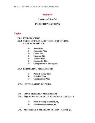
![NPTEL – ADVANCED FOUNDATION ENGINEERING-I
may be divided into two broad categories: (a) cased and (b) uncased. Both types may
have a pedestal at the bottom.
Cased piles are made by driving a steel casing into the ground with the help of a mandrel
placed inside the casing. When the pile reaches the proper depth, the mandrel is
withdrawn and the casing is filled with concrete. Figure 8.4a, b, c, and d show some
examples of cased piles without a pedestal. Table 1 gives additional information about
these cased piles. Figure 8.4 shows a cased pile with a pedestal. The pedestal is an
expanded concrete bulb that is formed by dropping a hammer on fresh concrete.
Figure 8.4 Cast-in-place concrete piles (see table 1 for descriptions)
Figure 8.4f and 8.4g are two types of uncased pile, one with a pedestal and the other
without. The uncased piles are made by first driving the casing to the desired depth and
then filling it with fresh concrete. The casing is then gradually withdrawn.
The allowable loads fore cast-in-place concrete piles are given by the following
equations,
Cased Pile
푄푄all = 퐴퐴푠푠푓푓푠푠 + 퐴퐴푐푐 푓푓푐푐 [8.2a]
Where](https://image.slidesharecdn.com/foundationanalysisanddesign-140910033213-phpapp02/85/Foundation-analysis-and-design-9-320.jpg)
![NPTEL – ADVANCED FOUNDATION ENGINEERING-I
퐴퐴푠푠 = area of cross section of steel
퐴퐴푐푐 = area of cross section of concrete
푓푓푠푠 = allowable stress of steel
푓푓푐푐 = allowable stress of concrete
Uncased Pile
푄푄all = 퐴퐴푐푐 푓푓푐푐 [2b]
Table 1 Description of the Cast-in-Place Piles Shown in figure 8. 4
Part in figure 8.
4 Name of pile Type of casing
Maximum usual depth of pile
(ft) (meter)
a Raymond Step-
Taper
Corrugated,
thin, cylindrical
casing
100 30
b Monotube or
Union Metal
Thin, fluted,
tapered steel
casing driven
without mandrel
130 40
c Western cased Thin sheet
casing
100-130 30-40
d Seamless pile or
Armco
Straight steel
pipe casing
160 50
e Franki cased
pedestal
Thin sheet
casing
100-130 30-40
f Western
uncased without
pedestal
- 50-65 15-20
g Franki uncased
pedestal
- 100-130 30-40
Timber Piles
Timber piles are tree trunks that have had their branches and bark carefully trimmed off.
The maximum length of most timber piles is 30-65 ft (10-20 m). To qualify for use as a
pile, the timber should be straight, sound, and without any defects. The American Society](https://image.slidesharecdn.com/foundationanalysisanddesign-140910033213-phpapp02/85/Foundation-analysis-and-design-10-320.jpg)

![NPTEL – ADVANCED FOUNDATION ENGINEERING-I
Timber piles can stay undamaged indefinitely if they are surrounded by saturated soil.
However, in a marine environment timber piles are subject to attack by various organisms
and can be damaged extensively in a few months. When located above the water table,
the piles are subject to attach by insects. The life of the piles may be increased by treating
them with preservatives such as creosote.
The allowable load-carrying capacity of wooden piles is
푄푄all = 퐴퐴푝푝 푓푓푤푤 [8.3]
Where
퐴퐴푝푝 = average area of cross section of the pile
푓푓푤푤 = allowable stress for the timber
The following allowable stresses are for pressure-treated round timber piles made from
Pacific Coast Douglas fir and Southern pine, when used in hydraulic structures (ASCE,
1993).
Allowable stress Pacific coast Douglas fir Southern pine
Compression parallel to
gain
875 lb/in2 (6.04 MN/m2) 825 lb/in2 (5.7MN/m2)
Bending 1700 lb/in2 (11.7 MN/
m2)
1650 lb/in2 (11.4 MN/
m2)
Horizontal shear 95 lb/in2 (0.66 MN/m2) 90 lb/in2 (0.62 MN/m2)
Compression perpendicular
to grain
190 lb/in2 (1.31 MN/m2) 205 lb/in2 (1.41 MN/m2)
Composite Piles
The upper and lower portions of composite piles are made of different materials. For
example, composite piles may be made of steel and concrete or timber and concrete. Steel
and concrete piles consist of a lower portion of steel and an upper portion of cast-in-place
concrete. This type of pile is the one used when the length of the pile required for
adequate bearing exceeds the capacity of simple cast-in-place concrete piles. Timber and
concrete piles usually consist of a lower portion of timber pile below the permanent water
table and an upper portion of concrete. In any case, forming proper joints between two
dissimilar materials is difficult, and, for that reason, composite piles are not widely used.
Comparison of Pile Types](https://image.slidesharecdn.com/foundationanalysisanddesign-140910033213-phpapp02/85/Foundation-analysis-and-design-12-320.jpg)


![NPTEL – ADVANCED FOUNDATION ENGINEERING-I
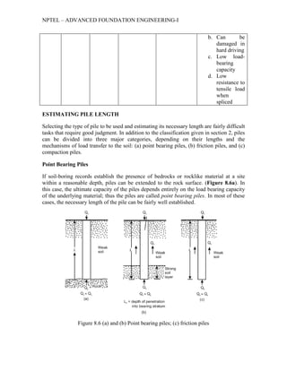
If, instead to bedrock, a fairly compact and hard stratum of soil is encountered at a
reasonable depth, piles can be extended a few meters into the hard stratum (figure 8. 6b).
Piles with pedestals can be constructed on the bed of the hard stratum, and the ultimate
pile load may be expressed as
푄푄푢푢 + 푄푄푝푝 + 푄푄푠푠 [8.4]
Where
푄푄푝푝 = load carried at the pile point
푄푄푠푠 = load carried by skin friction developed at the side of the pile (caused by
shearing resistance between the soil and the pile)
If 푄푄푠푠 is very small,
푄푄푢푢 ≈ 푄푄푝푝 [8.5]
In this case, the required pile length maybe estimated accurately if proper subsoil
exploration records are available.
Friction Piles
When no layer of rock or rocklike material is present at a reasonable depth at a site, point
bearing piles become very long and uneconomical. For this type o subsoil condition, piles
are driven through the softer material to specified depths (figure 8. 6c). The ultimate load
of these piles may be expressed by equation (4). However, if the value o 푄푄푝푝 is relatively
small,
푄푄푢푢 ≈ 푄푄푠푠 [8.6]
These piles are called friction piles because most of the resistance is derived from skin
friction. However, the term friction pile, although used often in the literature, is a
misnomer: in clayey soils, the resistance to applied load is also caused by adhesion.
The length of friction of piles depends on the shear strength of the soil, the applied load
and the pile size. To determine the necessary lengths of these piles, an engineer needs a
good understanding of soil-pile interaction, good judgment, and experience. Theoretical
procedures for the calculation of load-bearing capacity of piles are presented later in this
chapter.
Compaction Piles
Under certain circumstances, piles are driven in granular soils to achieve proper
compaction of soil close to the ground surface. These piles are called compaction piles.
The length of compaction piles depends on factors such as (a) relative density of the soil
before compaction, (b) desired relative density of the soil after compaction, and (c)
required depth of compaction. These piles are generally short; however, some field tests
are necessary to determine a reasonable length.](https://image.slidesharecdn.com/foundationanalysisanddesign-140910033213-phpapp02/85/Foundation-analysis-and-design-17-320.jpg)


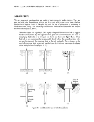
This document discusses pile foundations. It describes different types of piles including steel, concrete, timber, and composite piles. It discusses estimating pile length, installation methods, load transfer mechanisms, and methods for estimating pile capacity. Key points covered include the use of piles when upper soil layers are weak, to resist horizontal forces, in expansive soils, and for uplift resistance. Equations are provided for estimating allowable load capacity of different pile types.