1. Highway & Rail Transit Tunnel Maintenance &
Rehabilitation Manual
2005 Edition
Chapter 2: Tunnel Construction And Systems
A. Tunnel Types
This section describes the various types of highway and rail transit tunnels. These tunnel
types are described by their shape, liner type, invert type, construction method, and tunnel
finishes. It should be noted that other types may exist currently or be constructed in the future
as new technologies become available. The purpose of this section is to look at the types that
are most commonly used in tunnel construction to help the inspector properly classify any
given tunnel. As a general guideline a minimum length of 100 meters (~300 feet) was used in
defining a tunnel for inventory purposes. This length is primarily to exclude long underpasses,
however other reasons for using the tunnel classification may exist such as the presence of
lighting or a ventilation system, which could override the length limitation.
o 1. Shapes
a) Highway Tunnels
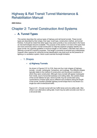
As shown in Figures 2.01 to 2.04, there are four main shapes of highway
tunnels - circular, rectangular, horseshoe, and oval/egg. The different shapes
typically relate to the method of construction and the ground conditions in
which they were constructed. Although many tunnels will appear rectangular
from inside, due to horizontal roadways and ceiling slabs, the outside shape
of the tunnel defines its type. Some tunnels may be constructed using
combinations of these types due to different soil conditions along the length
of the tunnel. Another possible highway tunnel shape that is not shown is a
single box with bi-directional traffic.
Figure 2.01 - Circular tunnel with two traffic lanes and one safety walk. Also
shown is an alternative ceiling slab. Invert may be solid concrete over liner or
a structural slab.
2. Figure 2.02 - Double box tunnel with two traffic lanes and one safety walk in
each box. Depending on location and loading conditions, center wall may be
solid or composed of consecutive columns.
Figure 2.03 - Horseshoe tunnel with two traffic lanes and one safety walk.
Also shown is an alternative ceiling slab. Invert may be a slab on grade or a
structural slab.
3. Figure 2.04 - Oval/egg tunnel with three traffic lanes and two safety walks.
Also shown is alternative ceiling slab.
b) Rail Transit Tunnels
Figures 2.05 to 2.09 show the typical shapes for rail transit tunnels. As with
highway tunnels, the shape typically relates to the method/ground conditions
in which they were constructed. The shape of rail transit tunnels often varies
along a given rail line. These shapes typically change at the transition
between the station structure and the typical tunnel cross-section. However,
the change in shape may also occur between stations due to variations in
ground conditions.
4. Figure 2.05 - Circular tunnel with a single track and one safety walk. Invert
slab is placed on top of liner.
Figure 2.06 - Double box tunnel with a single track and one safety walk in
each box. Depending on location and loading conditions, center wall may be
solid or composed of consecutive columns.
5. Figure 2.07 - Single box tunnel with a single track and one safety walk.
Tunnel is usually constructed beside another single box tunnel for opposite
direction travel.
6. Figure 2.08 - Horseshoe tunnel with a single track and one safety walk. This
shape typically exists in rock conditions and may be unlined within stable
rock formations.
7. Figure 2.09 - Oval tunnel with a single track and one safety walk.
8. o 2. Liner Types
Tunnel liner types can be described using the following classifications:
Unlined Rock
Rock Reinforcement Systems
Shotcrete
Ribbed Systems
Segmental Linings
Placed Concrete
Slurry Walls.
a) Unlined Rock
9. As the name suggests, an unlined rock tunnel is one in which no lining exists
for the majority of the tunnel length. Linings of other types may exist at
portals or at limited zones of weak rock. This type of liner was common in
older railroad tunnels in the western mountains, some of which have been
converted into highway tunnels for local access.
b) Rock Reinforcement Systems
Rock reinforcement systems are used to add additional stability to rock
tunnels in which structural defects exist in the rock. The intent of these
systems is to unify the rock pieces to produce a composite resistance to the
outside forces. Reinforcement systems include the use of metal straps and
mine ties with short bolts, untensioned steel dowels, or tensioned steel bolts.
To prevent small fragments of rock from spalling off the lining, wire mesh,
shotcrete, or a thin concrete lining may be used in conjunction with the above
systems.
c) Shotcrete
Shotcrete is appealing as a lining type due to its ease of application and short
"stand-up" time. Shotcrete is primarily used as a temporary application prior
to a final liner being installed or as a local solution to instabilities in a rock
tunnel. However, shotcrete can be used as a final lining. When this is the
case, it is typically placed in layers and can have metal or randomly-oriented,
synthetic fibers as reinforcement. The inside surface can be finished smooth
as with regular concrete; therefore, it is difficult to determine the lining type
without having knowledge of the construction method.
d) Ribbed Systems
Ribbed systems are typically a two-pass system for lining a drill-and-blast
rock tunnel. The first pass consists of timber, steel, or precast concrete ribs
usually with blocking between them. This provides structural stability to the
tunnel. The second pass typically consists of poured concrete that is placed
inside of the ribs. Another application of this system is to form the ribs using
prefabricated reinforcing bar cages embedded in multiple layers of shotcrete.
One other soft ground application is to place "barrel stave" timber lagging
between the ribs.
e) Segmental Linings
Segmental linings are primarily used in conjunction with a tunnel boring
machine (TBM) in soft ground conditions. The prefabricated lining segments
are erected within the cylindrical tail shield of the TBM. These prefabricated
segments can be made of steel, concrete, or cast iron and are usually bolted
together to compress gaskets for preventing water penetration.
f) Placed Concrete
Placed concrete linings are usually the final linings that are installed over any
of the previous initial stabilization methods. They can be used as a thin cover
layer over the primary liner to provide a finished surface within the tunnel or
to sandwich a waterproofing membrane. They can be reinforced or
unreinforced. They can be designed as a non-structural finish element or as
the main structural support for the tunnel.
10. g) Slurry Walls
Slurry wall construction types vary, but typically they consist of excavating a
trench that matches the proposed wall profile. This trench is continually kept
full with a drilling fluid during excavation, which stabilizes the sidewalls. Then
a reinforcing cage is lowered into the slurry or soldier piles are driven at a
predetermined interval and finally tremie concrete is placed into the
excavation, which displaces the drilling fluid. This procedure is repeated in
specified panel lengths, which are separated with watertight joints.
o 3. Invert Types
The invert of a tunnel is the slab on which the roadway or track bed is supported.
There are two main methods for supporting the roadway or track bed; one is by
placing the roadway or track bed directly on grade at the bottom of the tunnel
structure, and the other is to span the roadway between sidewalls to provide space
under the roadway for ventilation and utilities. The first method is used in most rail
transit tunnels because their ventilation systems rarely use supply ductwork under the
slab. This method is also employed in many highway tunnels over land where
ventilation is supplied from above the roadway level.
The second method is commonly found in circular highway tunnels that must provide
a horizontal roadway surface that is wide enough for at least two lanes of traffic and
therefore the roadway slab is suspended off the tunnel bottom a particular distance.
The void is then used for a ventilation plenum and other utilities. The roadway slab in
many of the older highway tunnels in New York City is supported by placing structural
steel beams, encased in concrete, that span transversely to the tunnel length, and
are spaced between 750 mm (30 in) and 1,500 mm (60 in) on centers. Newer
tunnels, similar to the second Hampton Roads Tunnel in Virginia, provide structural
reinforced concrete slabs that span the required distance between supports.
It is necessary to determine the type of roadway slab used in a given tunnel because
a more extensive inspection is required for a structural slab than for a slab-on-grade.
Examples of structural slabs in common tunnel shapes are shown in Figures 2.10 to
2.12.
Figure 2.10 - Circular tunnel with a structural slab that provides space for an air
plenum below.
11. Figure 2.11 - Single box tunnel with a structural slab that provides space for an air
plenum below.
12. Figure 2.12 - Horseshoe tunnel with a structural slab that provides space for an air
plenum below.
13. o 4. Construction Methods
As mentioned previously, the shape of the tunnel is largely dependent on the method
used to construct the tunnel. Table 2.1 lists the six main methods used for tunnel
construction with the shape that typically results. Brief descriptions of the construction
methods follow:
Table 2.01 - Construction Methods
Circular Horseshoe Rectangular
Cut and Cover X
Shield Driven X
Bored X
Drill and Blast X X
14. Table 2.01 - Construction Methods
Circular Horseshoe Rectangular
Immersed Tube X X
Sequential Excavation X
Jacked Tunnel X X
a) Cut and Cover
This method involves excavating an open trench in which the tunnel is
constructed to the design finish elevation and subsequently covered with
various compacted earthen materials and soils. Certain variations of this
method include using piles and lagging, tie back anchors or slurry wall
systems to construct the walls of a cut and cover tunnel.
b) Shield Driven
This method involves pushing a shield into the soft ground ahead. The
material inside the shield is removed and a lining system is constructed
before the shield is advanced further.
c) Bored
This method refers to using a mechanical TBM in which the full face of the
tunnel cross section is excavated at one time using a variety of cutting tools
that depend on ground conditions (soft ground or rock). The TBM is designed
to support the adjacent soil until temporary (and subsequently permanent)
linings are installed.
d) Drill and Blast
An alternative to using a TBM in rock situations would be to manually drill and
blast the rock and remove it using conventional conveyor techniques. This
method was commonly used for older tunnels and is still used when it is
determined cost effective or in difficult ground conditions.
e) Immersed Tube
When a canal, channel, river, etc., needs to be crossed, this method is often
used. A trench is dug at the water bottom and prefabricated tunnel segments
are made water tight and sunken into position where they are connected to
the other segments. Afterward, the trench may be backfilled with earth to
cover and protect the tunnel from the water-borne traffic, e.g., ships, barges,
and boats.
f) Sequential Excavation Method (SEM)
Soil in certain tunnels may have sufficient strength such that excavation of
the soil face by equipment in small increments is possible without direct
support. This excavation method is called the sequential excavation method.
Once excavated, the soil face is then supported using shotcrete and the
excavation is continued for the next segment. The cohesion of the rock or soil
can be increased by injecting grouts into the ground prior to excavation of
that segment.
15. g) Jacked Tunnels
The method of jacking a large tunnel underneath certain obstructions
(highways, buildings, rail lines, etc.) that prohibit the use of typical cut-and-
cover techniques for shallow tunnels has been used successfully in recent
years. This method is considered when the obstruction cannot be moved or
temporarily disturbed. First jacking pits are constructed. Then tunnel sections
are constructed in the jacking pit and forced by large hydraulic jacks into the
soft ground, which is systematically removed in front of the encroaching
tunnel section. Sometimes if the soil above the proposed tunnel is poor then
it is stabilized through various means such as grouting or freezing.
o 5. Tunnel Finishes
The interior finish of a tunnel is very important to the overall tunnel function. The
finishes must meet the following standards to ensure tunnel safety and ease of
maintenance:
Be designed to enhance tunnel lighting and visibility
Be fire resistant
Be precluded from producing toxic fumes during a fire
Be able to attenuate noise
Be easy to clean.
A brief description of the typical types of tunnel finishes that exist in highway tunnels
is given below. Transit tunnels often do not have an interior finish because the public
is not exposed to the tunnel lining except as the tunnel approaches the stations or
portals.
a) Ceramic Tile
This type of tunnel finish is the most widely used by tunnel owners. Tunnels
with a concrete or shotcrete inner lining are conducive to tile placement
because of their smooth surface. Ceramic tiles are extremely fire resistant,
economical, easily cleaned, and good reflectors of light due to the smooth,
glazed exterior finish. They are not; however, good sound attenuators, which
in new tunnels has been addressed through other means. Typically, tiles are
106 mm (4-¼ in) square are available in a wide variety of colors. They differ
from conventional ceramic tile in that they require a more secure connection
to the tunnel lining to prevent the tiles from falling onto the roadway below.
Even with a more secure connection, tiles may need to be replaced
eventually because of normal deterioration. Additional tiles are typically
purchased at the time of original construction since they are specifically made
for that tunnel. The additional amount purchased can be up to 10 percent of
the total tiled surface.
b) Porcelain-Enameled Metal Panels
Porcelain enamel is a combination of glass and inorganic color oxides that
are fused to metal under extremely high temperatures. This method is used
to coat most home appliances. The Porcelain Enamel Institute (PEI) has
established guidelines for the performance of porcelain enamel through the
following publications:
Appearance Properties (PEI 501)
16. Mechanical and Physical Properties (PEI 502)
Resistance to Corrosion (PEI 503)
High Temperature Properties (PEI 504)
Electrical Properties (PEI 505).
Porcelain enamel is typically applied to either cold-formed steel panels or
extruded aluminum panels. For ceilings, the panels are often filled with a
lightweight concrete; for walls, fiberglass boards are frequently used. The
attributes of porcelain-enameled panels are similar to those for ceramic tile
previously discussed; they are durable, easily washed, reflective, and come
in a variety of colors. As with ceramic tile, these panels are not good for
sound attenuation.
c) Epoxy-Coated Concrete
Epoxy coatings have been used on many tunnels during construction to
reduce costs. Durable paints have also been used. The epoxy is a
thermosetting resin that is chemically formulated for its toughness, strong
adhesion, reflective ability, and low shrinkage. Experience has shown that
these coatings do not withstand the harsh tunnel environmental conditions as
well as the others, resulting in the need to repair or rehabilitate more often.
d) Miscellaneous Finishes
There are a variety of other finishes that can be used on the walls or ceilings
of tunnels. Some of these finishes are becoming more popular due to their
improved sound absorptive properties, ease of replacement, and ability to
capitalize on the benefits of some of the materials mentioned above. Some of
the systems are listed below:
(1) Coated Cementboard Panels
These panels are not in wide use in American tunnels at this time,
but they offer a lightweight, fiber-reinforced cementboard that is
coated with baked enamel.
(2) Pre-cast Concrete Panels
This type of panel is often used as an alternative to metal panels;
however, a combination of the two is also possible where the metal
panel is applied as a veneer. Generally ceramic tile is cast into the
underside of the panel as the final finish.
(3) Metal Tiles
This tile system is uncommon, but has been used successfully in
certain tunnel applications. Metal tiles are coated with porcelain
enamel and are set in mortar similarly to ceramic tile.
B. VENTILATION SYSTEMS
o 1. Types
17. Tunnel ventilation systems can be categorized into five main types or any
combination of these five. The five types are as follows:
Natural Ventilation
Longitudinal Ventilation
Semi-Transverse Ventilation
Full-Transverse Ventilation
Single-Point Extraction.
It should be noted that ventilation systems are more applicable to highway tunnels
due to high concentration of contaminants. Rail transit tunnels often have ventilation
systems in the stations or at intermediate fan shafts, but during normal operations
rely mainly on the piston effect of the train pushing air through the tunnel to remove
stagnant air. Many rail transit tunnels have emergency mechanical ventilation that
only works in the event of a fire. For further information on tunnel ventilation systems
refer to NFPA 502 (National Fire Protection Association10).
a) Natural Ventilation
A naturally ventilated tunnel is as simple as the name implies. The movement
of air is controlled by meteorological conditions and the piston effect created
by moving traffic pushing the stale air through the tunnel. This effect is
minimized when bi-directional traffic is present. The meteorological conditions
include elevation and temperature differences between the two portals, and
wind blowing into the tunnel. Figure 2.13 shows a typical profile of a naturally
ventilated tunnel. Another configuration would be to add a center shaft that
allows for one more portal by which air can enter or exit the tunnel. Many
naturally ventilated tunnels over 180 m (600 ft) in length have mechanical
fans installed for use during a fire emergency.
Figure 2.13 - Natural Ventilation
b) Longitudinal Ventilation
Longitudinal ventilation is similar to natural ventilation with the addition of
mechanical fans, either in the portal buildings, the center shaft, or mounted
inside the tunnel. Longitudinal ventilation is often used inside rectangular-
shaped tunnels that do not have the extra space above the ceiling or below
the roadway for ductwork. Also, shorter circular tunnels may use the
longitudinal system since there is less air to replace; therefore, the need for
even distribution of air through ductwork is not necessary. The fans can be
reversible and are used to move air into or out of the tunnel. Figure 2.14
shows two different configurations of longitudinally ventilated tunnels.
Figure 2.14 - Longitudinal Ventilation
18. c) Semi-Transverse Ventilation
Semi-transverse ventilation also makes use of mechanical fans for movement
of air, but it does not use the roadway envelope itself as the ductwork. A
separate plenum or ductwork is added either above or below the tunnel with
flues that allow for uniform distribution of air into or out of the tunnel. This
plenum or ductwork is typically located above a suspended ceiling or below a
structural slab within a tunnel with a circular cross-section. Figure 2.15 shows
one example of a supply-air semi-transverse system and one example of an
exhaust-air semi-transverse system. It should be noted that there are many
variations of a semi-transverse system. One such variation would be to have
half the tunnel be a supply-air system and the other half an exhaust-air
system. Another variation is to have supply-air fans housed at both ends of
the plenum that push air directly into the plenum, towards the center of the
tunnel. One last variation is to have a system that can either be exhaust-air or
supply-air by utilizing reversible fans or a louver system in the ductwork that
can change the direction of the air. In all cases, air either enters or leaves at
both ends of the tunnel (bi-directional traffic flow) or on one end only (uni-
directional traffic flow).
Figure 2.15 - Semi-Transverse Ventilation
19. d) Full-Transverse Ventilation
Full-transverse ventilation uses the same components as semi-transverse
ventilation, but it incorporates supply air and exhaust air together over the
same length of tunnel. This method is used primarily for longer tunnels that
have large amounts of air that need to be replaced or for heavily traveled
tunnels that produce high levels of contaminants. The presence of supply and
exhaust ducts allows for a pressure difference between the roadway and the
ceiling; therefore, the air flows transverse to the tunnel length and is
circulated more frequently. This system may also incorporate supply or
exhaust ductwork along both sides of the tunnel instead of at the top and
bottom. Figure 2.16 shows an example of a full-transverse ventilation system.
Figure 2.16 - Full-Transverse Ventilation
e) Single-Point Extraction
In conjunction with semi- and full-transverse ventilation systems, single-point
extraction can be used to increase the airflow potential in the event of a fire in
20. the tunnel. The system works by allowing the opening size of select exhaust
flues to increase during an emergency. This can be done by mechanically
opening louvers or by constructing portions of the ceiling out of material that
would go from a solid to a gas during a fire, thus providing a larger opening.
Both of these methods are rather costly and thus are seldom used. Newer
tunnels achieve equal results simply by providing larger extraction ports at
given intervals that are connected to the fans through the ductwork.
o 2. Equipment
a) Fans
(1) Axial
There are two main types of axial fans - tube axial fans and vane
axial fans. Both types move air parallel to the impellor shaft, but the
difference between the two is the addition of guide vanes on one or
both sides of the impellor for the vane axial fans. These additional
vanes allow the fan to deliver pressures that are approximately four
times that of a typical tube axial fan. The two most common uses of
axial fans are to mount them horizontally on the tunnel ceiling at
given intervals along the tunnel or to mount them vertically within a
ventilation shaft that exits to the surface.
Figure 2.17 - Axial Fans
(2) Centrifugal
This type of fan outlets the air in a direction that is 90° to the direction
at which air is obtained. Air enters parallel to the shaft of the blades
and exits perpendicular to that. For tunnel applications, centrifugal
fans can either be backward-curved or airfoil-bladed. Centrifugal fans
are predominantly located within ventilation or portal buildings and
are connected to supply or exhaust ductwork. They are commonly
selected over axial fans due to their higher efficiency with less
horsepower required and are therefore less expensive to operate.
Figure 2.18 - Centrifugal Fan