1. Engineering mechanics deals with the behavior of physical bodies under the action of forces or displacements. It examines topics such as statics, dynamics, solid and fluid mechanics using principles from Newtonian physics.
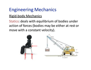
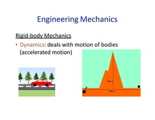
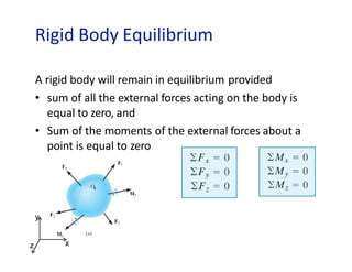
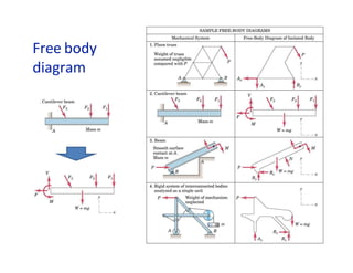
2. Statics analyzes bodies at rest or in constant motion, while dynamics considers bodies in motion and the forces involved in causing and changing that motion. Rigid body mechanics examines both topics for systems that do not deform under loading.
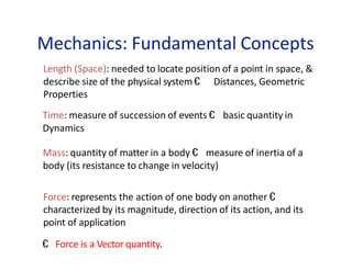
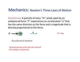
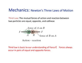
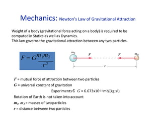
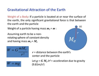
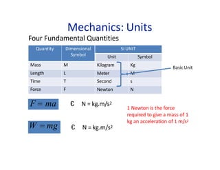
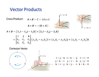
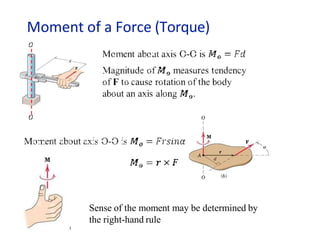
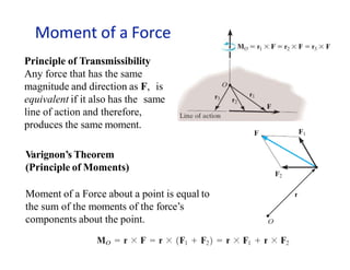
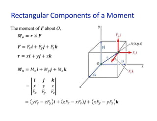
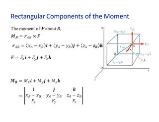
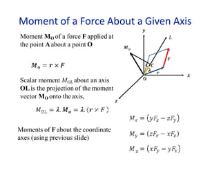
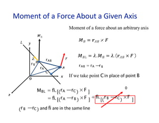
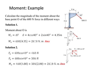
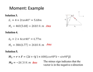
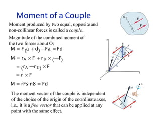
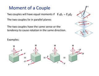
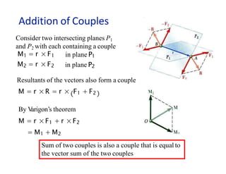
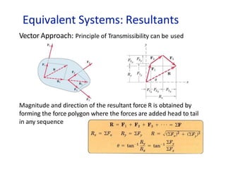
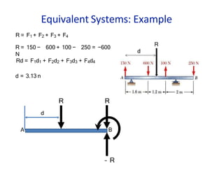
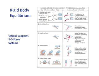
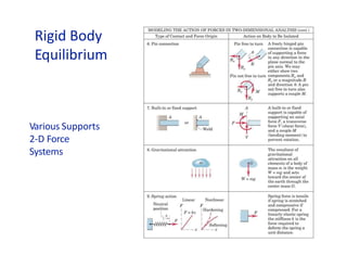
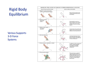
3. Fundamental concepts in mechanics include length, time, mass, and force. Newton's laws of motion describe how forces affect motion. Moments represent the tendency of forces to cause rotation and are important in mechanics of rigid bodies.