SlideShare a Scribd company logo
A Closer Look
 Definition
 History of FMS
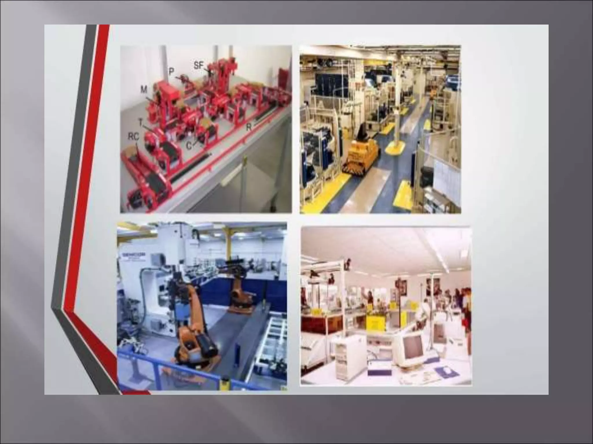
 FMS equipment
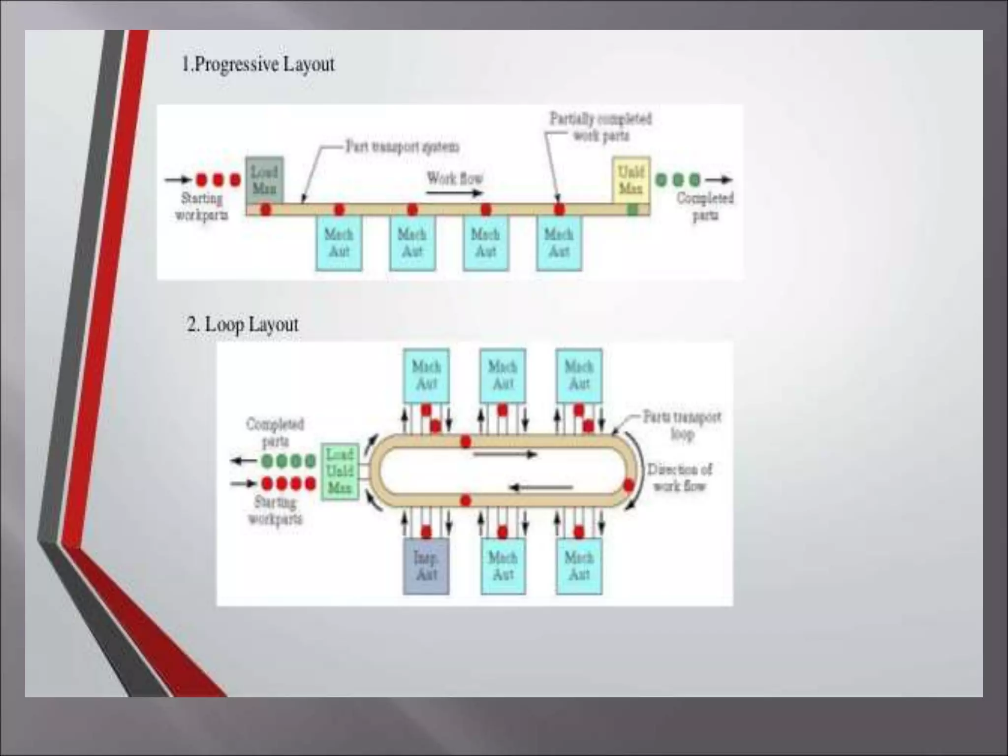
 Types of FMS
 Applications of FMS
 FSM different approaches
 Advantages
 Disadvantage
 Development of FMS
 Nuts and Bolts
 How FMS works
 A real world example
 Summary
A Flexible Manufacturing System (FMS) is a
production system consisting of a set of identical
and/or complementary numerically controlled
machine which are connected through an
automated transportation system.
each process in FMS is controlled by a
dedicated computer (FMS cell computer).
(Learn more…)
At the turn of the century FMS did not exist. There was not a big enough
need for efficiency because the markets were national and there was no foreign
competition. Manufacturers could tell the consumers what to buy. Henry Ford
is quoted as saying �people can order any color of car as long as it is
black.� This was the thinking of many big manufacturers of the time. After the
Second World War a new era in manufacturing was to come. The discovery of
new materials and production techniques increased quality and
productivity. The wars end open foreign markets and new competition. Now
the market focused on consumer and not the manufacturer. The first FMS was
patent in 1965 by Theo Williamson who made numerically controlled
equipment. Examples of numerically controlled equipment are like a CNC
lathes or mills which is called varying types of FMS. In the 70�s manufacturers
could not stay to date with the ever-growing technological knowledge
manufacturers competitors have, so FMS became mainstream in manufacturing.
In the 80�s for the first time manufacturers had to take in consideration
efficiency, quality, and flexibility to stay in business.
 Primary equipment
work centers
• Universal machining centers (prismatic FMSs)
• Turning centers (rotational FMSs)
• Grinding machines
• Nibbling machines
Process centers
• Wash machines
• Coordinate measuring machines
• Robotic work stations
• Manual workstations
 Secondary equipment
Support stations
• Pallet/fixture load/unload stations
• Tool commissioning/setting area
Support equipment
• Robots
• Pallet/fixture/stillage stores
• Pallet buffer stations
• Tools stores
• Raw material stores
• Transport system(AGVs,RGVs,robots)
• Transport units(pallets/stillages)
 Sequential FMS
 Random FMS
 Dedicated FMS
 Engineered FMS
 Modular FMS
 Metal-cutting machining
 Metal forming
 Assembly
 Joining-welding (arc , spot), glueing
 Surface treatment
 Inspection
 Testing
 The capability of producing different parts
without major retooling
 A measure of how fast the company converts
its process/es from making an old line of
products to produce a new product
 The ability to change a production schedule, to
modify a part, or to handle multiple parts
 To reduce set up and queue times
 Improve efficiency
 Reduce time for product completion
 Utilize human workers better
 Improve product routing
 Produce a variety of Items under one roof
 Improve product quality
 Serve a variety of vendors simultaneously
 Produce more product more quickly
 Limited ability to adapt to changes in product
or product mix (ex:machines are of limited capacity and the tooling
necessary for products, even of the same family, is not always feasible in a given FMS)
 Substantial pre-planning activity
 Expensive, costing millions of dollars
 Technological problems of exact component
positioning and precise timing necessary to
process a component
 Sophisticated manufacturing systems
 Several actions must be decided on before you can
have a have a FMS. These actions include.
 Selecting operations needed to make the product.
 Putting the operations in a logical order.
 Selecting equipment to make the product.
 Arranging the equipment for efficient use.
 Designing special devices to help build the product.
 Developing ways to control product quality.
 Testing the manufacturing system.
How Does It Work ?
 By implementing the components of robotics,
manufacturing technology and computer integrated
manufacturing in a correct order one can achieve a
successful Flexible Manufacturing System
An outline for Mechanical Engineering
CAD/CAM laboratory Integrated System
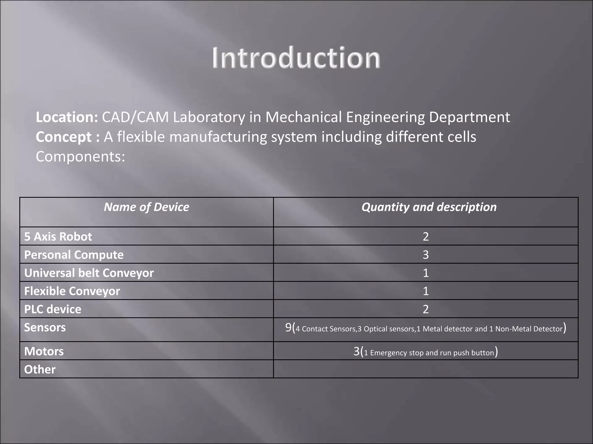
Name of Device Quantity and description
5 Axis Robot 2
Personal Compute 3
Universal belt Conveyor 1
Flexible Conveyor 1
PLC device 2
Sensors 9(4 Contact Sensors,3 Optical sensors,1 Metal detector and 1 Non-Metal Detector)
Motors 3(1 Emergency stop and run push button)
Other
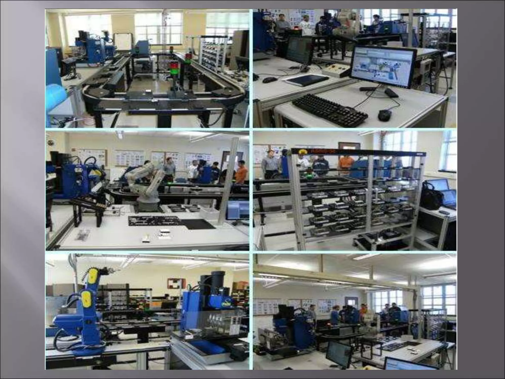
Location: CAD/CAM Laboratory in Mechanical Engineering Department
Concept : A flexible manufacturing system including different cells
Components:
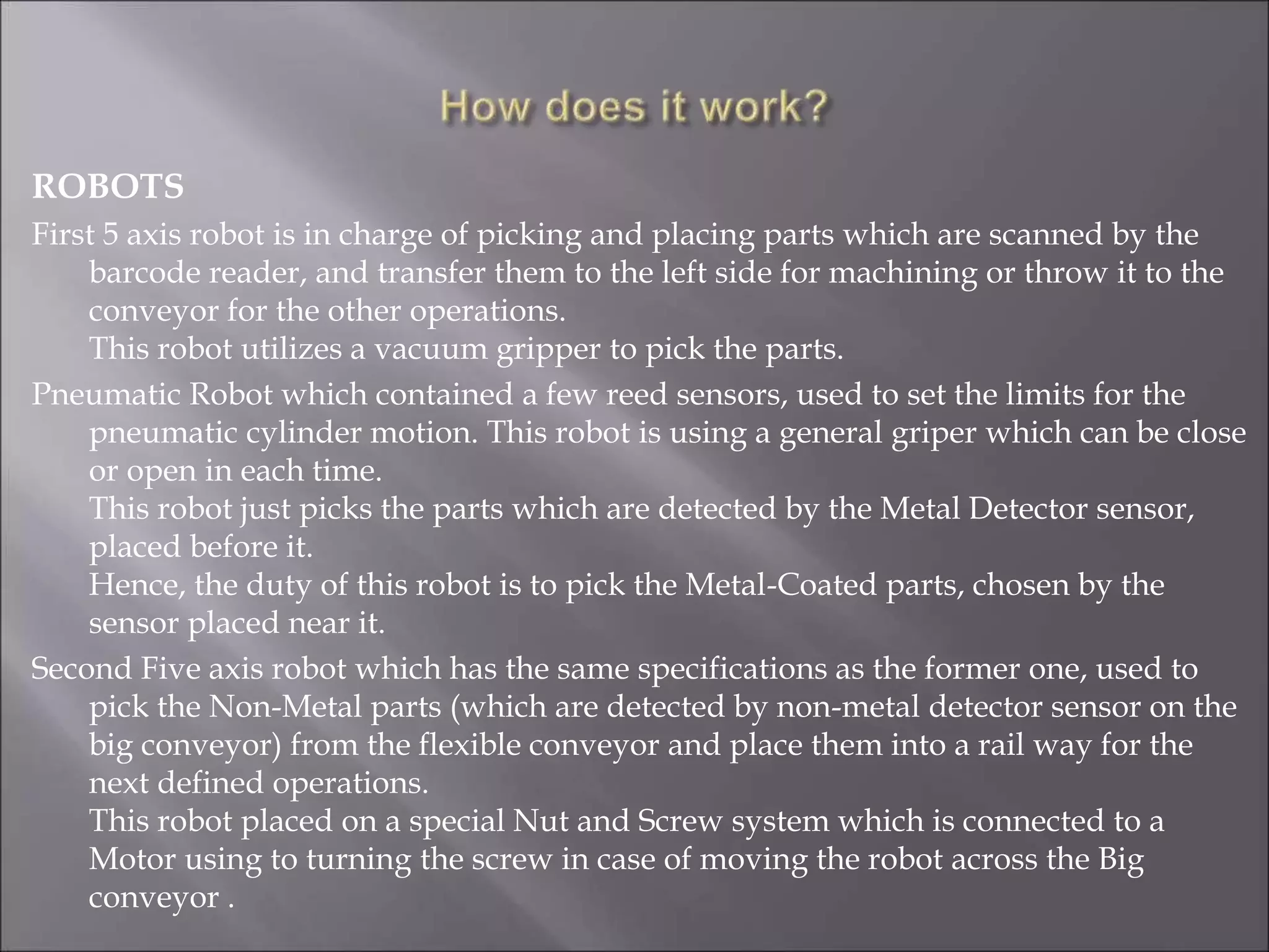
ROBOTS
First 5 axis robot is in charge of picking and placing parts which are scanned by the
barcode reader, and transfer them to the left side for machining or throw it to the
conveyor for the other operations.
This robot utilizes a vacuum gripper to pick the parts.
Pneumatic Robot which contained a few reed sensors, used to set the limits for the
pneumatic cylinder motion. This robot is using a general griper which can be close
or open in each time.
This robot just picks the parts which are detected by the Metal Detector sensor,
placed before it.
Hence, the duty of this robot is to pick the Metal-Coated parts, chosen by the
sensor placed near it.
Second Five axis robot which has the same specifications as the former one, used to
pick the Non-Metal parts (which are detected by non-metal detector sensor on the
big conveyor) from the flexible conveyor and place them into a rail way for the
next defined operations.
This robot placed on a special Nut and Screw system which is connected to a
Motor using to turning the screw in case of moving the robot across the Big
conveyor .
First robot second robot
pneumatic robot
COMPUTERS AND SOFTWARES
First Robot is controlled by a General PC, using a visual basic
program to read the barcodes and also control the robot’s motion.
For each part the program decide Where to be placed according to
the parts’ barcode
The second 5-axis robot is controlled by a PC using special software
which is named “Robotica”.
Generally, this software has a GIU (Graphical User Interface)
which can be used for programming the robot remotely. After
writing the program, by pressing the Run Button on the program
screen, each line transferred to the robot using a general RS-232
cable.
Also we have another PC which is used to monitor the Main PlC ,
placed in an anti dust cabin for safety.
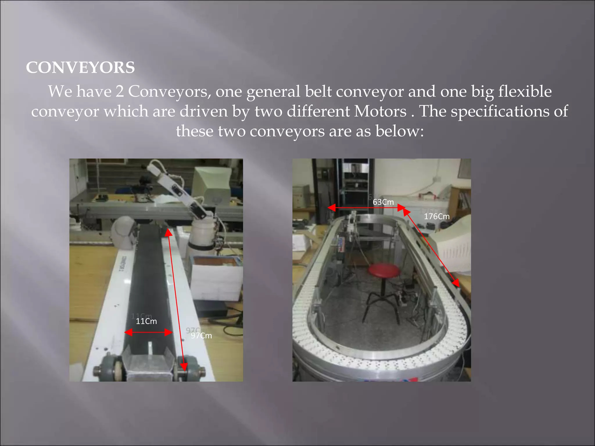
CONVEYORS
We have 2 Conveyors, one general belt conveyor and one big flexible
conveyor which are driven by two different Motors . The specifications of
these two conveyors are as below:
11Cm
97Cm
63Cm
176Cm
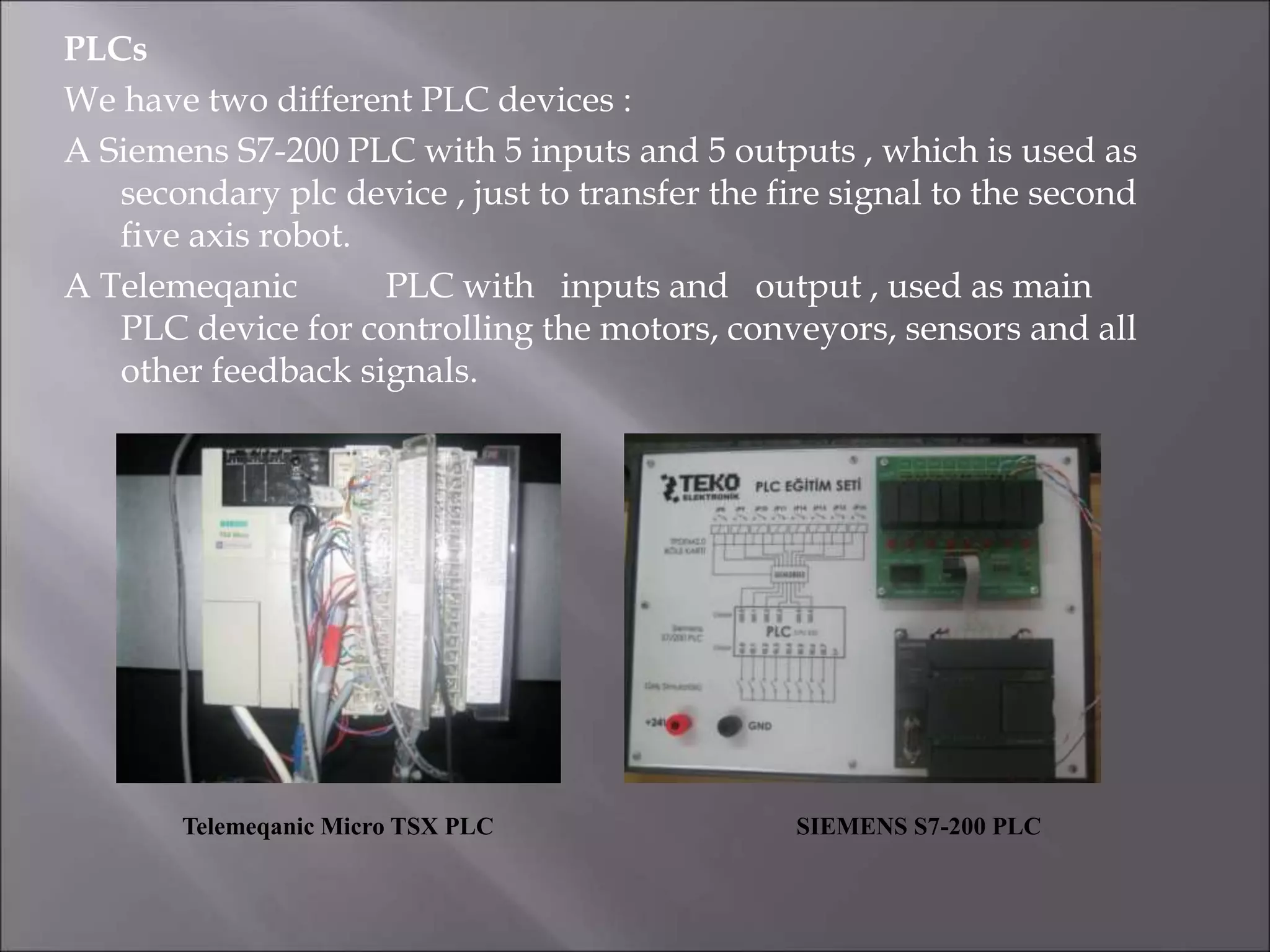
PLCs
We have two different PLC devices :
A Siemens S7-200 PLC with 5 inputs and 5 outputs , which is used as
secondary plc device , just to transfer the fire signal to the second
five axis robot.
A Telemeqanic PLC with inputs and output , used as main
PLC device for controlling the motors, conveyors, sensors and all
other feedback signals.
Telemeqanic Micro TSX PLC SIEMENS S7-200 PLC
Computer integrated manufacturing and PLC
In today’s manufacturing units several PLCs are used to switch on
or off robots ,conveyer belts and other part of manufacturing
systems. The advantages of PLC in automated systems made PLC
one of the main component of any Manufacturing unit.
1 2
Host
computer
Raw
Materials
Area
Swarf
disposal
Universal Machining Center
AGV transport system 1
AGV transport system 2
Universal Machining Center
Head
Indexing
Machines
Wash
Machine
Coordinate
Measuring
Machine
Assembly
Cells
1 & 2
Finish
Machine
Cell
Piecepart
Buffer
Area
One Design + One Assembly Process = Multiple Models
When different models are designed to be assembled in the same sequence they can be built
in the same plant.
This maximizes efficiency and allows the company to respond quickly to changing customer
Through the use of reprogrammable tooling in the body shop, standardized equipment in the
paint shop and common build sequence in final assembly, Ford can build multiple models on
one or more platforms in one plant.
In the body shop, where
the sheet metal comes
together to form the
vehicle’s body, flexibility
means more than 80
percent of the tooling is
not specific to one model.
It can be reprogrammed to
weld a car or a truck or a
crossover of similar size.
Body Shop
In the paint shop, flexibility
means robotic applicators
are programmed to cover
various body styles – as
they move through the
paint booth – with equal
precision. This results in
minimizing waste and
environmental impact
while maximizing quality.
Paint Shop
In the final assembly
area, flexibility means
the build sequence is the
same among multiple
models on one or more
platforms allowing for
efficient utilization of
people and equipment.
Final Assembly
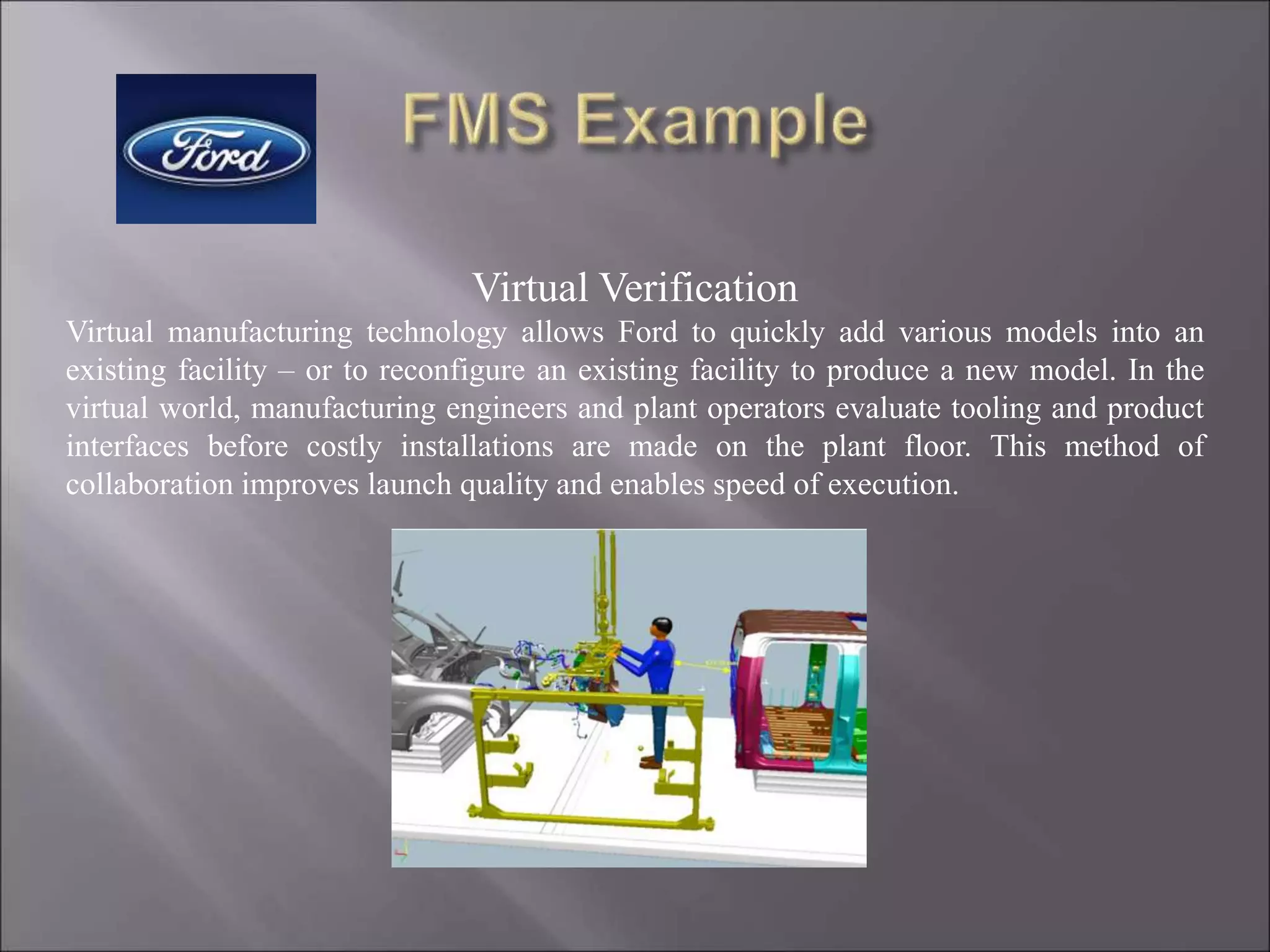
Virtual Verification
Virtual manufacturing technology allows Ford to quickly add various models into an
existing facility – or to reconfigure an existing facility to produce a new model. In the
virtual world, manufacturing engineers and plant operators evaluate tooling and product
interfaces before costly installations are made on the plant floor. This method of
collaboration improves launch quality and enables speed of execution.
Thank you

More Related Content

Similar to FMS unit 4 cim.ppt

Flexible manufacturing system
Flexible manufacturing systemFlexible manufacturing system
Flexible manufacturing system
Designage Solutions
 
CAD CAM 1 Module-3 Part-A 18ME72
CAD CAM  1 Module-3 Part-A 18ME72CAD CAM  1 Module-3 Part-A 18ME72
CAD CAM 1 Module-3 Part-A 18ME72
Mohammed Imran
 
FMS IN CAD/CAM TYPES HISTORY ADVANTAGES PPT_final.pptx
FMS IN CAD/CAM  TYPES HISTORY ADVANTAGES PPT_final.pptxFMS IN CAD/CAM  TYPES HISTORY ADVANTAGES PPT_final.pptx
FMS IN CAD/CAM TYPES HISTORY ADVANTAGES PPT_final.pptx
PraveenVundrajavarap
 
Industrial applications of robots
Industrial applications of robotsIndustrial applications of robots
Industrial applications of robots
CKSunith1
 
MANUFACTURING OF MILLING HEAD – ON KTM 760 BY USING CNC PART PROGRAMING
MANUFACTURING OF MILLING HEAD – ON KTM 760 BY USING   CNC PART PROGRAMINGMANUFACTURING OF MILLING HEAD – ON KTM 760 BY USING   CNC PART PROGRAMING
MANUFACTURING OF MILLING HEAD – ON KTM 760 BY USING CNC PART PROGRAMING
ShalinisinghSolanki
 
66281324-Flexible-Manufacturing-Systems.ppt
66281324-Flexible-Manufacturing-Systems.ppt66281324-Flexible-Manufacturing-Systems.ppt
66281324-Flexible-Manufacturing-Systems.ppt
TAMILSELVANNATARAJAN3
 
FMS-1.ppt .
FMS-1.ppt                                        .FMS-1.ppt                                        .
FMS-1.ppt .
Athar739197
 
Automated Process
Automated ProcessAutomated Process
Automated ProcessMOHD ARISH
 
Flexible Manufacturing Systems V2 090310
Flexible Manufacturing Systems V2 090310Flexible Manufacturing Systems V2 090310
Flexible Manufacturing Systems V2 090310
Leicester College- Technology & Engineering Centre
 
Flexible manufacturing systems analysis
Flexible manufacturing systems analysisFlexible manufacturing systems analysis
Flexible manufacturing systems analysis
Nachiketas Waychal
 
FMS.ppt
FMS.pptFMS.ppt
Motion control application for clean room robot
Motion control application for clean room robotMotion control application for clean room robot
Motion control application for clean room robotElmo Motion Control
 
Digital transformation
Digital transformationDigital transformation
Digital transformation
shivani12380
 
CNC vs Robot
CNC vs RobotCNC vs Robot
CNC vs Robot
AV&R
 
plant layout
plant layoutplant layout
plant layout
PAARTH GUPTA
 
Kawasaki Robotics and InduSoft Web Studio: Kawasaki Presentation
Kawasaki Robotics and InduSoft Web Studio: Kawasaki PresentationKawasaki Robotics and InduSoft Web Studio: Kawasaki Presentation
Kawasaki Robotics and InduSoft Web Studio: Kawasaki Presentation
AVEVA
 
Flexible Manufacturing System
Flexible Manufacturing SystemFlexible Manufacturing System
Flexible Manufacturing System
Desai Vaishali
 
Automated Systems General Foundation
Automated Systems General FoundationAutomated Systems General Foundation
Automated Systems General Foundationmrcarty
 
Flexible Manufacturing System, Advantages and DIsadvantages of FMS
Flexible Manufacturing System, Advantages and DIsadvantages of FMSFlexible Manufacturing System, Advantages and DIsadvantages of FMS
Flexible Manufacturing System, Advantages and DIsadvantages of FMS
RajivB10
 

Similar to FMS unit 4 cim.ppt (20)

Flexible manufacturing system
Flexible manufacturing systemFlexible manufacturing system
Flexible manufacturing system
 
CAD CAM 1 Module-3 Part-A 18ME72
CAD CAM  1 Module-3 Part-A 18ME72CAD CAM  1 Module-3 Part-A 18ME72
CAD CAM 1 Module-3 Part-A 18ME72
 
FMS IN CAD/CAM TYPES HISTORY ADVANTAGES PPT_final.pptx
FMS IN CAD/CAM  TYPES HISTORY ADVANTAGES PPT_final.pptxFMS IN CAD/CAM  TYPES HISTORY ADVANTAGES PPT_final.pptx
FMS IN CAD/CAM TYPES HISTORY ADVANTAGES PPT_final.pptx
 
Industrial applications of robots
Industrial applications of robotsIndustrial applications of robots
Industrial applications of robots
 
MANUFACTURING OF MILLING HEAD – ON KTM 760 BY USING CNC PART PROGRAMING
MANUFACTURING OF MILLING HEAD – ON KTM 760 BY USING   CNC PART PROGRAMINGMANUFACTURING OF MILLING HEAD – ON KTM 760 BY USING   CNC PART PROGRAMING
MANUFACTURING OF MILLING HEAD – ON KTM 760 BY USING CNC PART PROGRAMING
 
66281324-Flexible-Manufacturing-Systems.ppt
66281324-Flexible-Manufacturing-Systems.ppt66281324-Flexible-Manufacturing-Systems.ppt
66281324-Flexible-Manufacturing-Systems.ppt
 
FMS-1.ppt .
FMS-1.ppt                                        .FMS-1.ppt                                        .
FMS-1.ppt .
 
Automated Process
Automated ProcessAutomated Process
Automated Process
 
Flexible Manufacturing Systems V2 090310
Flexible Manufacturing Systems V2 090310Flexible Manufacturing Systems V2 090310
Flexible Manufacturing Systems V2 090310
 
Flexible manufacturing systems analysis
Flexible manufacturing systems analysisFlexible manufacturing systems analysis
Flexible manufacturing systems analysis
 
FMS.ppt
FMS.pptFMS.ppt
FMS.ppt
 
4.resource management
4.resource management4.resource management
4.resource management
 
Motion control application for clean room robot
Motion control application for clean room robotMotion control application for clean room robot
Motion control application for clean room robot
 
Digital transformation
Digital transformationDigital transformation
Digital transformation
 
CNC vs Robot
CNC vs RobotCNC vs Robot
CNC vs Robot
 
plant layout
plant layoutplant layout
plant layout
 
Kawasaki Robotics and InduSoft Web Studio: Kawasaki Presentation
Kawasaki Robotics and InduSoft Web Studio: Kawasaki PresentationKawasaki Robotics and InduSoft Web Studio: Kawasaki Presentation
Kawasaki Robotics and InduSoft Web Studio: Kawasaki Presentation
 
Flexible Manufacturing System
Flexible Manufacturing SystemFlexible Manufacturing System
Flexible Manufacturing System
 
Automated Systems General Foundation
Automated Systems General FoundationAutomated Systems General Foundation
Automated Systems General Foundation
 
Flexible Manufacturing System, Advantages and DIsadvantages of FMS
Flexible Manufacturing System, Advantages and DIsadvantages of FMSFlexible Manufacturing System, Advantages and DIsadvantages of FMS
Flexible Manufacturing System, Advantages and DIsadvantages of FMS
 

More from TAMILSELVANNATARAJAN3

Project_work_-_1st_review_Presentation_dt._28-12-2021.pptx
Project_work_-_1st_review_Presentation_dt._28-12-2021.pptxProject_work_-_1st_review_Presentation_dt._28-12-2021.pptx
Project_work_-_1st_review_Presentation_dt._28-12-2021.pptx
TAMILSELVANNATARAJAN3
 
Heat-Exchanger-Classification-and-Selection-II.pdf
Heat-Exchanger-Classification-and-Selection-II.pdfHeat-Exchanger-Classification-and-Selection-II.pdf
Heat-Exchanger-Classification-and-Selection-II.pdf
TAMILSELVANNATARAJAN3
 
unit-1-Basics of metrology.pptx
unit-1-Basics of metrology.pptxunit-1-Basics of metrology.pptx
unit-1-Basics of metrology.pptx
TAMILSELVANNATARAJAN3
 
MT-I U-I PART I .pptx
MT-I U-I  PART I .pptxMT-I U-I  PART I .pptx
MT-I U-I PART I .pptx
TAMILSELVANNATARAJAN3
 
Industrial robotics.pptx
Industrial robotics.pptxIndustrial robotics.pptx
Industrial robotics.pptx
TAMILSELVANNATARAJAN3
 
EDC PDF UNIT 1.pdf
EDC PDF UNIT 1.pdfEDC PDF UNIT 1.pdf
EDC PDF UNIT 1.pdf
TAMILSELVANNATARAJAN3
 
6978130
69781306978130

More from TAMILSELVANNATARAJAN3 (9)

Project_work_-_1st_review_Presentation_dt._28-12-2021.pptx
Project_work_-_1st_review_Presentation_dt._28-12-2021.pptxProject_work_-_1st_review_Presentation_dt._28-12-2021.pptx
Project_work_-_1st_review_Presentation_dt._28-12-2021.pptx
 
Heat-Exchanger-Classification-and-Selection-II.pdf
Heat-Exchanger-Classification-and-Selection-II.pdfHeat-Exchanger-Classification-and-Selection-II.pdf
Heat-Exchanger-Classification-and-Selection-II.pdf
 
ROBOTICS PPT.pdf
ROBOTICS PPT.pdfROBOTICS PPT.pdf
ROBOTICS PPT.pdf
 
unit-1-Basics of metrology.pptx
unit-1-Basics of metrology.pptxunit-1-Basics of metrology.pptx
unit-1-Basics of metrology.pptx
 
MT-I U-I PART I .pptx
MT-I U-I  PART I .pptxMT-I U-I  PART I .pptx
MT-I U-I PART I .pptx
 
ch01.ppt
ch01.pptch01.ppt
ch01.ppt
 
Industrial robotics.pptx
Industrial robotics.pptxIndustrial robotics.pptx
Industrial robotics.pptx
 
EDC PDF UNIT 1.pdf
EDC PDF UNIT 1.pdfEDC PDF UNIT 1.pdf
EDC PDF UNIT 1.pdf
 
6978130
69781306978130
6978130
 

Recently uploaded

Cosmetic shop management system project report.pdf
Cosmetic shop management system project report.pdfCosmetic shop management system project report.pdf
Cosmetic shop management system project report.pdf
Kamal Acharya
 
Event Management System Vb Net Project Report.pdf
Event Management System Vb Net  Project Report.pdfEvent Management System Vb Net  Project Report.pdf
Event Management System Vb Net Project Report.pdf
Kamal Acharya
 
AKS UNIVERSITY Satna Final Year Project By OM Hardaha.pdf
AKS UNIVERSITY Satna Final Year Project By OM Hardaha.pdfAKS UNIVERSITY Satna Final Year Project By OM Hardaha.pdf
AKS UNIVERSITY Satna Final Year Project By OM Hardaha.pdf
SamSarthak3
 
NO1 Uk best vashikaran specialist in delhi vashikaran baba near me online vas...
NO1 Uk best vashikaran specialist in delhi vashikaran baba near me online vas...NO1 Uk best vashikaran specialist in delhi vashikaran baba near me online vas...
NO1 Uk best vashikaran specialist in delhi vashikaran baba near me online vas...
Amil Baba Dawood bangali
 
Final project report on grocery store management system..pdf
Final project report on grocery store management system..pdfFinal project report on grocery store management system..pdf
Final project report on grocery store management system..pdf
Kamal Acharya
 
CFD Simulation of By-pass Flow in a HRSG module by R&R Consult.pptx
CFD Simulation of By-pass Flow in a HRSG module by R&R Consult.pptxCFD Simulation of By-pass Flow in a HRSG module by R&R Consult.pptx
CFD Simulation of By-pass Flow in a HRSG module by R&R Consult.pptx
R&R Consult
 
Nuclear Power Economics and Structuring 2024
Nuclear Power Economics and Structuring 2024Nuclear Power Economics and Structuring 2024
Nuclear Power Economics and Structuring 2024
Massimo Talia
 
Vaccine management system project report documentation..pdf
Vaccine management system project report documentation..pdfVaccine management system project report documentation..pdf
Vaccine management system project report documentation..pdf
Kamal Acharya
 
Courier management system project report.pdf
Courier management system project report.pdfCourier management system project report.pdf
Courier management system project report.pdf
Kamal Acharya
 
TECHNICAL TRAINING MANUAL GENERAL FAMILIARIZATION COURSE
TECHNICAL TRAINING MANUAL   GENERAL FAMILIARIZATION COURSETECHNICAL TRAINING MANUAL   GENERAL FAMILIARIZATION COURSE
TECHNICAL TRAINING MANUAL GENERAL FAMILIARIZATION COURSE
DuvanRamosGarzon1
 
Industrial Training at Shahjalal Fertilizer Company Limited (SFCL)
Industrial Training at Shahjalal Fertilizer Company Limited (SFCL)Industrial Training at Shahjalal Fertilizer Company Limited (SFCL)
Industrial Training at Shahjalal Fertilizer Company Limited (SFCL)
MdTanvirMahtab2
 
J.Yang, ICLR 2024, MLILAB, KAIST AI.pdf
J.Yang,  ICLR 2024, MLILAB, KAIST AI.pdfJ.Yang,  ICLR 2024, MLILAB, KAIST AI.pdf
J.Yang, ICLR 2024, MLILAB, KAIST AI.pdf
MLILAB
 
Architectural Portfolio Sean Lockwood
Architectural Portfolio Sean LockwoodArchitectural Portfolio Sean Lockwood
Architectural Portfolio Sean Lockwood
seandesed
 
Standard Reomte Control Interface - Neometrix
Standard Reomte Control Interface - NeometrixStandard Reomte Control Interface - Neometrix
Standard Reomte Control Interface - Neometrix
Neometrix_Engineering_Pvt_Ltd
 
ASME IX(9) 2007 Full Version .pdf
ASME IX(9)  2007 Full Version       .pdfASME IX(9)  2007 Full Version       .pdf
ASME IX(9) 2007 Full Version .pdf
AhmedHussein950959
 
Sachpazis:Terzaghi Bearing Capacity Estimation in simple terms with Calculati...
Sachpazis:Terzaghi Bearing Capacity Estimation in simple terms with Calculati...Sachpazis:Terzaghi Bearing Capacity Estimation in simple terms with Calculati...
Sachpazis:Terzaghi Bearing Capacity Estimation in simple terms with Calculati...
Dr.Costas Sachpazis
 
Planning Of Procurement o different goods and services
Planning Of Procurement o different goods and servicesPlanning Of Procurement o different goods and services
Planning Of Procurement o different goods and services
JoytuBarua2
 
DESIGN A COTTON SEED SEPARATION MACHINE.docx
DESIGN A COTTON SEED SEPARATION MACHINE.docxDESIGN A COTTON SEED SEPARATION MACHINE.docx
DESIGN A COTTON SEED SEPARATION MACHINE.docx
FluxPrime1
 
power quality voltage fluctuation UNIT - I.pptx
power quality voltage fluctuation UNIT - I.pptxpower quality voltage fluctuation UNIT - I.pptx
power quality voltage fluctuation UNIT - I.pptx
ViniHema
 
Design and Analysis of Algorithms-DP,Backtracking,Graphs,B&B
Design and Analysis of Algorithms-DP,Backtracking,Graphs,B&BDesign and Analysis of Algorithms-DP,Backtracking,Graphs,B&B
Design and Analysis of Algorithms-DP,Backtracking,Graphs,B&B
Sreedhar Chowdam
 

Recently uploaded (20)

Cosmetic shop management system project report.pdf
Cosmetic shop management system project report.pdfCosmetic shop management system project report.pdf
Cosmetic shop management system project report.pdf
 
Event Management System Vb Net Project Report.pdf
Event Management System Vb Net  Project Report.pdfEvent Management System Vb Net  Project Report.pdf
Event Management System Vb Net Project Report.pdf
 
AKS UNIVERSITY Satna Final Year Project By OM Hardaha.pdf
AKS UNIVERSITY Satna Final Year Project By OM Hardaha.pdfAKS UNIVERSITY Satna Final Year Project By OM Hardaha.pdf
AKS UNIVERSITY Satna Final Year Project By OM Hardaha.pdf
 
NO1 Uk best vashikaran specialist in delhi vashikaran baba near me online vas...
NO1 Uk best vashikaran specialist in delhi vashikaran baba near me online vas...NO1 Uk best vashikaran specialist in delhi vashikaran baba near me online vas...
NO1 Uk best vashikaran specialist in delhi vashikaran baba near me online vas...
 
Final project report on grocery store management system..pdf
Final project report on grocery store management system..pdfFinal project report on grocery store management system..pdf
Final project report on grocery store management system..pdf
 
CFD Simulation of By-pass Flow in a HRSG module by R&R Consult.pptx
CFD Simulation of By-pass Flow in a HRSG module by R&R Consult.pptxCFD Simulation of By-pass Flow in a HRSG module by R&R Consult.pptx
CFD Simulation of By-pass Flow in a HRSG module by R&R Consult.pptx
 
Nuclear Power Economics and Structuring 2024
Nuclear Power Economics and Structuring 2024Nuclear Power Economics and Structuring 2024
Nuclear Power Economics and Structuring 2024
 
Vaccine management system project report documentation..pdf
Vaccine management system project report documentation..pdfVaccine management system project report documentation..pdf
Vaccine management system project report documentation..pdf
 
Courier management system project report.pdf
Courier management system project report.pdfCourier management system project report.pdf
Courier management system project report.pdf
 
TECHNICAL TRAINING MANUAL GENERAL FAMILIARIZATION COURSE
TECHNICAL TRAINING MANUAL   GENERAL FAMILIARIZATION COURSETECHNICAL TRAINING MANUAL   GENERAL FAMILIARIZATION COURSE
TECHNICAL TRAINING MANUAL GENERAL FAMILIARIZATION COURSE
 
Industrial Training at Shahjalal Fertilizer Company Limited (SFCL)
Industrial Training at Shahjalal Fertilizer Company Limited (SFCL)Industrial Training at Shahjalal Fertilizer Company Limited (SFCL)
Industrial Training at Shahjalal Fertilizer Company Limited (SFCL)
 
J.Yang, ICLR 2024, MLILAB, KAIST AI.pdf
J.Yang,  ICLR 2024, MLILAB, KAIST AI.pdfJ.Yang,  ICLR 2024, MLILAB, KAIST AI.pdf
J.Yang, ICLR 2024, MLILAB, KAIST AI.pdf
 
Architectural Portfolio Sean Lockwood
Architectural Portfolio Sean LockwoodArchitectural Portfolio Sean Lockwood
Architectural Portfolio Sean Lockwood
 
Standard Reomte Control Interface - Neometrix
Standard Reomte Control Interface - NeometrixStandard Reomte Control Interface - Neometrix
Standard Reomte Control Interface - Neometrix
 
ASME IX(9) 2007 Full Version .pdf
ASME IX(9)  2007 Full Version       .pdfASME IX(9)  2007 Full Version       .pdf
ASME IX(9) 2007 Full Version .pdf
 
Sachpazis:Terzaghi Bearing Capacity Estimation in simple terms with Calculati...
Sachpazis:Terzaghi Bearing Capacity Estimation in simple terms with Calculati...Sachpazis:Terzaghi Bearing Capacity Estimation in simple terms with Calculati...
Sachpazis:Terzaghi Bearing Capacity Estimation in simple terms with Calculati...
 
Planning Of Procurement o different goods and services
Planning Of Procurement o different goods and servicesPlanning Of Procurement o different goods and services
Planning Of Procurement o different goods and services
 
DESIGN A COTTON SEED SEPARATION MACHINE.docx
DESIGN A COTTON SEED SEPARATION MACHINE.docxDESIGN A COTTON SEED SEPARATION MACHINE.docx
DESIGN A COTTON SEED SEPARATION MACHINE.docx
 
power quality voltage fluctuation UNIT - I.pptx
power quality voltage fluctuation UNIT - I.pptxpower quality voltage fluctuation UNIT - I.pptx
power quality voltage fluctuation UNIT - I.pptx
 
Design and Analysis of Algorithms-DP,Backtracking,Graphs,B&B
Design and Analysis of Algorithms-DP,Backtracking,Graphs,B&BDesign and Analysis of Algorithms-DP,Backtracking,Graphs,B&B
Design and Analysis of Algorithms-DP,Backtracking,Graphs,B&B
 

FMS unit 4 cim.ppt

  • 2.  Definition  History of FMS  FMS equipment  Types of FMS  Applications of FMS  FSM different approaches  Advantages  Disadvantage  Development of FMS  Nuts and Bolts  How FMS works  A real world example  Summary
  • 3. A Flexible Manufacturing System (FMS) is a production system consisting of a set of identical and/or complementary numerically controlled machine which are connected through an automated transportation system. each process in FMS is controlled by a dedicated computer (FMS cell computer). (Learn more…)
  • 4. At the turn of the century FMS did not exist. There was not a big enough need for efficiency because the markets were national and there was no foreign competition. Manufacturers could tell the consumers what to buy. Henry Ford is quoted as saying �people can order any color of car as long as it is black.� This was the thinking of many big manufacturers of the time. After the Second World War a new era in manufacturing was to come. The discovery of new materials and production techniques increased quality and productivity. The wars end open foreign markets and new competition. Now the market focused on consumer and not the manufacturer. The first FMS was patent in 1965 by Theo Williamson who made numerically controlled equipment. Examples of numerically controlled equipment are like a CNC lathes or mills which is called varying types of FMS. In the 70�s manufacturers could not stay to date with the ever-growing technological knowledge manufacturers competitors have, so FMS became mainstream in manufacturing. In the 80�s for the first time manufacturers had to take in consideration efficiency, quality, and flexibility to stay in business.
  • 5.  Primary equipment work centers • Universal machining centers (prismatic FMSs) • Turning centers (rotational FMSs) • Grinding machines • Nibbling machines Process centers • Wash machines • Coordinate measuring machines • Robotic work stations • Manual workstations
  • 6.  Secondary equipment Support stations • Pallet/fixture load/unload stations • Tool commissioning/setting area Support equipment • Robots • Pallet/fixture/stillage stores • Pallet buffer stations • Tools stores • Raw material stores • Transport system(AGVs,RGVs,robots) • Transport units(pallets/stillages)
  • 7.
  • 8.  Sequential FMS  Random FMS  Dedicated FMS  Engineered FMS  Modular FMS
  • 9.  Metal-cutting machining  Metal forming  Assembly  Joining-welding (arc , spot), glueing  Surface treatment  Inspection  Testing
  • 10.  The capability of producing different parts without major retooling  A measure of how fast the company converts its process/es from making an old line of products to produce a new product  The ability to change a production schedule, to modify a part, or to handle multiple parts
  • 11.  To reduce set up and queue times  Improve efficiency  Reduce time for product completion  Utilize human workers better  Improve product routing  Produce a variety of Items under one roof  Improve product quality  Serve a variety of vendors simultaneously  Produce more product more quickly
  • 12.  Limited ability to adapt to changes in product or product mix (ex:machines are of limited capacity and the tooling necessary for products, even of the same family, is not always feasible in a given FMS)  Substantial pre-planning activity  Expensive, costing millions of dollars  Technological problems of exact component positioning and precise timing necessary to process a component  Sophisticated manufacturing systems
  • 13.  Several actions must be decided on before you can have a have a FMS. These actions include.  Selecting operations needed to make the product.  Putting the operations in a logical order.  Selecting equipment to make the product.  Arranging the equipment for efficient use.  Designing special devices to help build the product.  Developing ways to control product quality.  Testing the manufacturing system.
  • 14.
  • 15.
  • 16.
  • 17.
  • 18.
  • 19.
  • 20.
  • 21.
  • 22.
  • 23. How Does It Work ?
  • 24.  By implementing the components of robotics, manufacturing technology and computer integrated manufacturing in a correct order one can achieve a successful Flexible Manufacturing System
  • 25.
  • 26. An outline for Mechanical Engineering CAD/CAM laboratory Integrated System
  • 27. Name of Device Quantity and description 5 Axis Robot 2 Personal Compute 3 Universal belt Conveyor 1 Flexible Conveyor 1 PLC device 2 Sensors 9(4 Contact Sensors,3 Optical sensors,1 Metal detector and 1 Non-Metal Detector) Motors 3(1 Emergency stop and run push button) Other Location: CAD/CAM Laboratory in Mechanical Engineering Department Concept : A flexible manufacturing system including different cells Components:
  • 28. ROBOTS First 5 axis robot is in charge of picking and placing parts which are scanned by the barcode reader, and transfer them to the left side for machining or throw it to the conveyor for the other operations. This robot utilizes a vacuum gripper to pick the parts. Pneumatic Robot which contained a few reed sensors, used to set the limits for the pneumatic cylinder motion. This robot is using a general griper which can be close or open in each time. This robot just picks the parts which are detected by the Metal Detector sensor, placed before it. Hence, the duty of this robot is to pick the Metal-Coated parts, chosen by the sensor placed near it. Second Five axis robot which has the same specifications as the former one, used to pick the Non-Metal parts (which are detected by non-metal detector sensor on the big conveyor) from the flexible conveyor and place them into a rail way for the next defined operations. This robot placed on a special Nut and Screw system which is connected to a Motor using to turning the screw in case of moving the robot across the Big conveyor .
  • 29. First robot second robot pneumatic robot
  • 30. COMPUTERS AND SOFTWARES First Robot is controlled by a General PC, using a visual basic program to read the barcodes and also control the robot’s motion. For each part the program decide Where to be placed according to the parts’ barcode The second 5-axis robot is controlled by a PC using special software which is named “Robotica”. Generally, this software has a GIU (Graphical User Interface) which can be used for programming the robot remotely. After writing the program, by pressing the Run Button on the program screen, each line transferred to the robot using a general RS-232 cable. Also we have another PC which is used to monitor the Main PlC , placed in an anti dust cabin for safety.
  • 31. CONVEYORS We have 2 Conveyors, one general belt conveyor and one big flexible conveyor which are driven by two different Motors . The specifications of these two conveyors are as below: 11Cm 97Cm 63Cm 176Cm
  • 32. PLCs We have two different PLC devices : A Siemens S7-200 PLC with 5 inputs and 5 outputs , which is used as secondary plc device , just to transfer the fire signal to the second five axis robot. A Telemeqanic PLC with inputs and output , used as main PLC device for controlling the motors, conveyors, sensors and all other feedback signals. Telemeqanic Micro TSX PLC SIEMENS S7-200 PLC
  • 33. Computer integrated manufacturing and PLC In today’s manufacturing units several PLCs are used to switch on or off robots ,conveyer belts and other part of manufacturing systems. The advantages of PLC in automated systems made PLC one of the main component of any Manufacturing unit.
  • 34. 1 2 Host computer Raw Materials Area Swarf disposal Universal Machining Center AGV transport system 1 AGV transport system 2 Universal Machining Center Head Indexing Machines Wash Machine Coordinate Measuring Machine Assembly Cells 1 & 2 Finish Machine Cell Piecepart Buffer Area
  • 35. One Design + One Assembly Process = Multiple Models When different models are designed to be assembled in the same sequence they can be built in the same plant. This maximizes efficiency and allows the company to respond quickly to changing customer
  • 36. Through the use of reprogrammable tooling in the body shop, standardized equipment in the paint shop and common build sequence in final assembly, Ford can build multiple models on one or more platforms in one plant. In the body shop, where the sheet metal comes together to form the vehicle’s body, flexibility means more than 80 percent of the tooling is not specific to one model. It can be reprogrammed to weld a car or a truck or a crossover of similar size. Body Shop In the paint shop, flexibility means robotic applicators are programmed to cover various body styles – as they move through the paint booth – with equal precision. This results in minimizing waste and environmental impact while maximizing quality. Paint Shop In the final assembly area, flexibility means the build sequence is the same among multiple models on one or more platforms allowing for efficient utilization of people and equipment. Final Assembly
  • 37. Virtual Verification Virtual manufacturing technology allows Ford to quickly add various models into an existing facility – or to reconfigure an existing facility to produce a new model. In the virtual world, manufacturing engineers and plant operators evaluate tooling and product interfaces before costly installations are made on the plant floor. This method of collaboration improves launch quality and enables speed of execution.