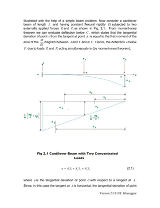
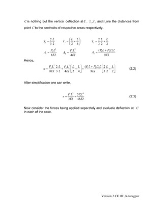
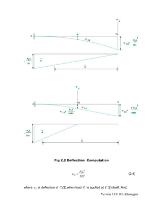
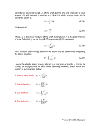
SlideShare a Scribd company logo
1 of 21
Download to read offline
Module
              1
Energy Methods in
Structural Analysis
           Version 2 CE IIT, Kharagpur
Lesson
          2
    Principle of
Superposition,
 Strain Energy

       Version 2 CE IIT, Kharagpur
Instructional Objectives
After reading this lesson, the student will be able to
1. State and use principle of superposition.
2. Explain strain energy concept.
3. Differentiate between elastic and inelastic strain energy and state units of
   strain energy.
4. Derive an expression for strain energy stored in one-dimensional structure
   under axial load.
5. Derive an expression for elastic strain energy stored in a beam in bending.
6. Derive an expression for elastic strain energy stored in a beam in shear.
7. Derive an expression for elastic strain energy stored in a circular shaft under
   torsion.


2.1 Introduction
In the analysis of statically indeterminate structures, the knowledge of the
displacements of a structure is necessary. Knowledge of displacements is also
required in the design of members. Several methods are available for the
calculation of displacements of structures. However, if displacements at only a
few locations in structures are required then energy based methods are most
suitable. If displacements are required to solve statically indeterminate
structures, then only the relative values of EA, EI and GJ are required. If actual
value of displacement is required as in the case of settlement of supports and
temperature stress calculations, then it is necessary to know actual values of
 E and G . In general deflections are small compared with the dimensions of
structure but for clarity the displacements are drawn to a much larger scale than
the structure itself. Since, displacements are small, it is assumed not to cause
gross displacements of the geometry of the structure so that equilibrium equation
can be based on the original configuration of the structure. When non-linear
behaviour of the structure is considered then such an assumption is not valid as
the structure is appreciably distorted. In this lesson two of the very important
concepts i.e., principle of superposition and strain energy method will be
introduced.


2.2 Principle of Superposition
The principle of superposition is a central concept in the analysis of structures.
This is applicable when there exists a linear relationship between external forces
and corresponding structural displacements. The principle of superposition may
be stated as the deflection at a given point in a structure produced by several
loads acting simultaneously on the structure can be found by superposing
deflections at the same point produced by loads acting individually. This is

                                                         Version 2 CE IIT, Kharagpur
illustrated with the help of a simple beam problem. Now consider a cantilever
beam of length L and having constant flexural rigidity EI subjected to two
externally applied forces P1 and P2 as shown in Fig. 2.1. From moment-area
theorem we can evaluate deflection below C , which states that the tangential
deviation of point c from the tangent at point A is equal to the first moment of the
             M
area of the     diagram between A and C about C . Hence, the deflection u below
             EI
 C due to loads P1 and P2 acting simultaneously is (by moment-area theorem),


                            u = A1 x1 + A2 x 2 + A3 x3                       (2.1)


where u is the tangential deviation of point C with respect to a tangent at A .
Since, in this case the tangent at A is horizontal, the tangential deviation of point

                                                         Version 2 CE IIT, Kharagpur
C is nothing but the vertical deflection at C . x1 , x2 and x3 are the distances from
point C to the centroids of respective areas respectively.


                     2L             ⎛ L L⎞                  2L L
              x1 =             x2 = ⎜ + ⎟            x3 =     +
                     32             ⎝2 4⎠                   32 2

                   P2 L2            P2 L2                   ( P1 L + P2 L) L
              A1 =             A2 =                  A3 =
                   8 EI             4 EI                          8EI
Hence,
                     P2 L2 2 L P2 L2 ⎡ L L ⎤ (P1 L + P2 L) L ⎡ 2 L L ⎤
              u=              +         +    +               ⎢3 2 + 2 ⎥           (2.2)
                     8EI 3 2 4 EI ⎢ 2 4 ⎥
                                     ⎣     ⎦      8 EI       ⎣        ⎦


After simplification one can write,


                                    P2 L3 5 P1 L3
                               u=        +                                        (2.3)
                                    3EI 48EI

Now consider the forces being applied separately and evaluate deflection at C
in each of the case.


                                                              Version 2 CE IIT, Kharagpur
P2 L3
                                    u 22 =                                        (2.4)
                                             3EI


where u 22 is deflection at C (2) when load P1 is applied at C (2) itself. And,

                                                          Version 2 CE IIT, Kharagpur
1 P1 L L ⎡ L 2 L ⎤ 5P1 L3
                     u 21 =             +      =                                 (2.5)
                            2 2 EI 2 ⎢ 2 3 2 ⎥ 48EI
                                     ⎣       ⎦


where u 21 is the deflection at C (2) when load is applied at B (1) . Now the total
deflection at C when both the loads are applied simultaneously is obtained by
adding u 22 and u 21 .

                                             P2 L3 5 P1 L3
                         u = u 22 + u 21 =        +                              (2.6)
                                             3EI 48 EI


Hence it is seen from equations (2.3) and (2.6) that when the structure behaves
linearly, the total deflection caused by forces P1 , P2 ,...., Pn at any point in the
structure is the sum of deflection caused by forces P1 , P2 ,...., Pn acting
independently on the structure at the same point. This is known as the Principle
of Superposition.
The method of superposition is not valid when the material stress-strain
relationship is non-linear. Also, it is not valid in cases where the geometry of
structure changes on application of load. For example, consider a hinged-hinged
beam-column subjected to only compressive force as shown in Fig. 2.3(a). Let
the compressive force P be less than the Euler’s buckling load of the structure.
                                                   1
Then deflection at an arbitrary point C (say) u c is zero. Next, the same beam-
column be subjected to lateral load Q with no axial load as shown in Fig. 2.3(b).
Let the deflection of the beam-column at C be u c2 . Now consider the case when
the same beam-column is subjected to both axial load P and lateral load Q . As
                                                                    3
per the principle of superposition, the deflection at the centre u c must be the sum
of deflections caused by P and Q when applied individually. However this is not
so in the present case. Because of lateral deflection caused by Q , there will be
                                                                              3
additional bending moment due to P at C .Hence, the net deflection u c will be
more than the sum of deflections u c and u c2 .
                                   1


                                                             Version 2 CE IIT, Kharagpur
2.3 Strain Energy
Consider an elastic spring as shown in the Fig.2.4. When the spring is slowly
pulled, it deflects by a small amount u1 . When the load is removed from the
spring, it goes back to the original position. When the spring is pulled by a force,
it does some work and this can be calculated once the load-displacement
relationship is known. It may be noted that, the spring is a mathematical
idealization of the rod being pulled by a force P axially. It is assumed here that
the force is applied gradually so that it slowly increases from zero to a maximum
value P . Such a load is called static loading, as there are no inertial effects due
to motion. Let the load-displacement relationship be as shown in Fig. 2.5. Now,
work done by the external force may be calculated as,

                              1       1
                     Wext =     P1u1 = ( force × displacement )                 (2.7)
                              2       2

                                                            Version 2 CE IIT, Kharagpur
The area enclosed by force-displacement curve gives the total work done by the
externally applied load. Here it is assumed that the energy is conserved i.e. the
work done by gradually applied loads is equal to energy stored in the structure.
This internal energy is known as strain energy. Now strain energy stored in a
spring is
                                       1
                                    U = P u1
                                         1                               (2.8)
                                       2

                                                      Version 2 CE IIT, Kharagpur
Work and energy are expressed in the same units. In SI system, the unit of work
and energy is the joule (J), which is equal to one Newton metre (N.m). The strain
energy may also be defined as the internal work done by the stress resultants in
moving through the corresponding deformations. Consider an infinitesimal
element within a three dimensional homogeneous and isotropic material. In the
most general case, the state of stress acting on such an element may be as
shown in Fig. 2.6. There are normal stresses (σ x , σ y and σ z ) and shear stresses
(τ   xy   ,τ yz and τ zx ) acting on the element. Corresponding to normal and shear
stresses we have normal and shear strains. Now strain energy may be written
as,


                                                    1 T
                                                    2∫
                                             U=        σ ε dv                                                    (2.9)
                                                     v


in which σ T is the transpose of the stress column vector i.e.,

             {σ }   = (σ x , σ y , σ z ,τ xy ,τ yz ,τ zx ) and {ε } = ( ε x , ε y , ε z , ε xy , ε yz , ε zx )
                T                                                      T
                                                                                                                 (2.10)


                                                                                           Version 2 CE IIT, Kharagpur
The strain energy may be further classified as elastic strain energy and inelastic
strain energy as shown in Fig. 2.7. If the force P is removed then the spring
shortens. When the elastic limit of the spring is not exceeded, then on removal of
load, the spring regains its original shape. If the elastic limit of the material is
exceeded, a permanent set will remain on removal of load. In the present case,
load the spring beyond its elastic limit. Then we obtain the load-displacement
curve OABCDO as shown in Fig. 2.7. Now if at B, the load is removed, the spring
gradually shortens. However, a permanent set of OD is till retained. The shaded
area BCD is known as the elastic strain energy. This can be recovered upon
removing the load. The area OABDO represents the inelastic portion of strain
energy.


The area OABCDO corresponds to strain energy stored in the structure. The area
OABEO is defined as the complementary strain energy. For the linearly elastic
structure it may be seen that

Area OBC = Area OBE

i.e. Strain energy = Complementary strain energy

This is not the case always as observed from Fig. 2.7. The complementary
energy has no physical meaning. The definition is being used for its convenience
in structural analysis as will be clear from the subsequent chapters.

                                                        Version 2 CE IIT, Kharagpur
Usually structural member is subjected to any one or the combination of bending
moment; shear force, axial force and twisting moment. The member resists these
external actions by internal stresses. In this section, the internal stresses induced
in the structure due to external forces and the associated displacements are
calculated for different actions. Knowing internal stresses due to individual
forces, one could calculate the resulting stress distribution due to combination of
external forces by the method of superposition. After knowing internal stresses
and deformations, one could easily evaluate strain energy stored in a simple
beam due to axial, bending, shear and torsional deformations.

2.3.1 Strain energy under axial load
Consider a member of constant cross sectional area A , subjected to axial force
 P as shown in Fig. 2.8. Let E be the Young’s modulus of the material. Let the
member be under equilibrium under the action of this force, which is applied
through the centroid of the cross section. Now, the applied force P is resisted by
                                                                     P
uniformly distributed internal stresses given by average stress σ =     as shown
                                                                     A
by the free body diagram (vide Fig. 2.8). Under the action of axial load P
applied at one end gradually, the beam gets elongated by (say) u . This may be
calculated as follows. The incremental elongation du of small element of length
 dx of beam is given by,

                                          σ              P
                            du = ε dx =           dx =      dx                       (2.11)
                                              E          AE

Now the total elongation of the member of length L may be obtained by
integration

                                          L
                                              P
                                   u=∫           dx                                  (2.12)
                                          0
                                              AE


                                                                 Version 2 CE IIT, Kharagpur
1
Now the work done by external loads W =      Pu                             (2.13)
                                           2
In a conservative system, the external work is stored as the internal strain
energy. Hence, the strain energy stored in the bar in axial deformation is,

                                        1
                                   U=     Pu                               (2.14)
                                        2

Substituting equation (2.12) in (2.14) we get,

                                                       Version 2 CE IIT, Kharagpur
L
                                  P2
                          U =∫        dx                                 (2.15)
                               0
                                 2 AE


2.3.2 Strain energy due to bending
Consider a prismatic beam subjected to loads as shown in the Fig. 2.9. The
loads are assumed to act on the beam in a plane containing the axis of symmetry
of the cross section and the beam axis. It is assumed that the transverse cross
sections (such as AB and CD), which are perpendicular to centroidal axis, remain
plane and perpendicular to the centroidal axis of beam (as shown in Fig 2.9).


                                                     Version 2 CE IIT, Kharagpur
Version 2 CE IIT, Kharagpur
Consider a small segment of beam of length ds subjected to bending moment as
shown in the Fig. 2.9. Now one cross section rotates about another cross section
by a small amount dθ . From the figure,

                                    1      M
                            dθ =      ds =    ds                            (2.16)
                                    R      EI

where R is the radius of curvature of the bent beam and EI is the flexural rigidity
of the beam. Now the work done by the moment M while rotating through angle
dθ will be stored in the segment of beam as strain energy dU . Hence,
                                 1
                            dU = M dθ                                      (2.17)
                                 2

Substituting for dθ in equation (2.17), we get,

                                 1 M2
                            dU =      ds                                    (2.18)
                                 2 EI

Now, the energy stored in the complete beam of span L may be obtained by
integrating equation (2.18). Thus,

                                L
                                  M2
                           U =∫        ds                                   (2.19)
                                0
                                  2 EI


                                                       Version 2 CE IIT, Kharagpur
2.3.3 Strain energy due to transverse shear


                                              Version 2 CE IIT, Kharagpur
The shearing stress on a cross section of beam of rectangular cross section may
be found out by the relation

                                        VQ
                                   τ=                                         (2.20)
                                        bI ZZ

where Q is the first moment of the portion of the cross-sectional area above the
point where shear stress is required about neutral axis, V is the transverse shear
force, b is the width of the rectangular cross-section and I zz is the moment of
inertia of the cross-sectional area about the neutral axis. Due to shear stress, the
angle between the lines which are originally at right angle will change. The shear
stress varies across the height in a parabolic manner in the case of a rectangular
cross-section. Also, the shear stress distribution is different for different shape of
the cross section. However, to simplify the computation shear stress is assumed
to be uniform (which is strictly not correct) across the cross section. Consider a
segment of length ds subjected to shear stress τ . The shear stress across the
cross section may be taken as

                                           V
                                   τ =k
                                           A

 in which A is area of the cross-section and k is the form factor which is
dependent on the shape of the cross section. One could write, the deformation
du as

                                    du = Δγ ds                                (2.21)

where Δγ is the shear strain and is given by

                                            τ        V
                                    Δγ =        =k                            (2.22)
                                            G        AG

Hence, the total deformation of the beam due to the action of shear force is

                                           L    V
                                    u=∫ k          ds                         (2.23)
                                        0       AG

Now the strain energy stored in the beam due to the action of transverse shear
force is given by,

                                            2
                               1       L kV
                            U = Vu = ∫        ds                              (2.24)
                               2      0 2 AG


                                                          Version 2 CE IIT, Kharagpur
The strain energy due to transverse shear stress is very low compared to strain
energy due to bending and hence is usually neglected. Thus the error induced in
assuming a uniform shear stress across the cross section is very small.


2.3.4 Strain energy due to torsion


Consider a circular shaft of length L radius R , subjected to a torque T at one
end (see Fig. 2.11). Under the action of torque one end of the shaft rotates with
respect to the fixed end by an angle dφ . Hence the strain energy stored in the
shaft is,
                                      1
                                  U = Tφ                                  (2.25)
                                      2


                                                      Version 2 CE IIT, Kharagpur
Consider an elemental length ds of the shaft. Let the one end rotates by a small
amount dφ with respect to another end. Now the strain energy stored in the
elemental length is,
                                      1
                                dU = Tdφ                                 (2.26)
                                      2

We know that
                                            Tds
                                     dφ =                                (2.27)
                                            GJ

where, G is the shear modulus of the shaft material and J is the polar moment
of area. Substituting for dφ from (2.27) in equation (2.26), we obtain

                                           T2
                                     dU =     ds                         (2.28)
                                          2GJ

Now, the total strain energy stored in the beam may be obtained by integrating
the above equation.
                                            2
                                        L T
                                  U =∫        ds                       (2.29)
                                       0 2GJ


Hence the elastic strain energy stored in a member of length s (it may be
curved or straight) due to axial force, bending moment, shear force and
torsion is summarized below.

                             s
                                P2
1. Due to axial force   U1 = ∫      ds
                             0
                               2 AE

                              s
                                M2
2. Due to bending       U2 = ∫       ds
                              0
                                2 EI

                              s
                                 V2
3. Due to shear         U3 = ∫       ds
                              0
                                2 AG

                                 s
                                 T2
4. Due to torsion       U4 = ∫      ds
                              0
                                2GJ


                                                     Version 2 CE IIT, Kharagpur
Summary
In this lesson, the principle of superposition has been stated and proved. Also, its
limitations have been discussed. In section 2.3, it has been shown that the elastic
strain energy stored in a structure is equal to the work done by applied loads in
deforming the structure. The strain energy expression is also expressed for a 3-
dimensional homogeneous and isotropic material in terms of internal stresses
and strains in a body. In this lesson, the difference between elastic and inelastic
strain energy is explained. Complementary strain energy is discussed. In the
end, expressions are derived for calculating strain stored in a simple beam due to
axial load, bending moment, transverse shear force and torsion.


                                                        Version 2 CE IIT, Kharagpur

More Related Content

What's hot

elastic constants
elastic constantselastic constants
elastic constantsKaran Patel
 
Strain Energy and Modulus Of Resilience
Strain Energy and Modulus Of ResilienceStrain Energy and Modulus Of Resilience
Strain Energy and Modulus Of ResilienceLotachukwu Ernest Eze
 
Lecture 5 castigliono's theorem
Lecture 5 castigliono's theoremLecture 5 castigliono's theorem
Lecture 5 castigliono's theoremDeepak Agarwal
 
Lec5 total potential_energy_method
Lec5 total potential_energy_methodLec5 total potential_energy_method
Lec5 total potential_energy_methodMahdi Damghani
 
11. kinetics of particles work energy method
11. kinetics of particles work energy method11. kinetics of particles work energy method
11. kinetics of particles work energy methodEkeeda
 
10. kinetics of particles newton s 2nd law
10. kinetics of particles newton s 2nd law10. kinetics of particles newton s 2nd law
10. kinetics of particles newton s 2nd lawEkeeda
 
Kinetics of Particles-Work Energy Method
Kinetics of Particles-Work Energy MethodKinetics of Particles-Work Energy Method
Kinetics of Particles-Work Energy MethodEkeeda
 
Kinetics of particles work and energy
Kinetics of particles work and energyKinetics of particles work and energy
Kinetics of particles work and energyGrace Palermo
 
Work and energy
Work and energyWork and energy
Work and energysibo081
 
Principle of virtual work and unit load method
Principle of virtual work and unit load methodPrinciple of virtual work and unit load method
Principle of virtual work and unit load methodMahdi Damghani
 
6161103 11.3 principle of virtual work for a system of connected rigid bodies
6161103 11.3 principle of virtual work for a system of connected rigid bodies6161103 11.3 principle of virtual work for a system of connected rigid bodies
6161103 11.3 principle of virtual work for a system of connected rigid bodiesetcenterrbru
 
Energy principle in structure analysis in civil engineering
Energy principle in structure analysis in civil engineeringEnergy principle in structure analysis in civil engineering
Energy principle in structure analysis in civil engineeringNagma Modi
 
Chapter 8 principle of virtual work
Chapter 8 principle of virtual workChapter 8 principle of virtual work
Chapter 8 principle of virtual workramana4uiitm
 
9. kinematics of particles
9. kinematics of particles9. kinematics of particles
9. kinematics of particlesEkeeda
 
Virtual work modified [compatibility mode](1)
Virtual work modified [compatibility mode](1)Virtual work modified [compatibility mode](1)
Virtual work modified [compatibility mode](1)sharancm2009
 
008 newton's second law of motion
008 newton's second law of motion008 newton's second law of motion
008 newton's second law of motionphysics101
 
Movimiento De Una Partícula Cargada En Un Campo Eléctrico Y En Un Campo Magné...
Movimiento De Una Partícula Cargada En Un Campo Eléctrico Y En Un Campo Magné...Movimiento De Una Partícula Cargada En Un Campo Eléctrico Y En Un Campo Magné...
Movimiento De Una Partícula Cargada En Un Campo Eléctrico Y En Un Campo Magné...Gregory Zuñiga
 

What's hot (19)

elastic constants
elastic constantselastic constants
elastic constants
 
Strain Energy and Modulus Of Resilience
Strain Energy and Modulus Of ResilienceStrain Energy and Modulus Of Resilience
Strain Energy and Modulus Of Resilience
 
Lecture 5 castigliono's theorem
Lecture 5 castigliono's theoremLecture 5 castigliono's theorem
Lecture 5 castigliono's theorem
 
Timoshenko beam-element
Timoshenko beam-elementTimoshenko beam-element
Timoshenko beam-element
 
Lec5 total potential_energy_method
Lec5 total potential_energy_methodLec5 total potential_energy_method
Lec5 total potential_energy_method
 
11. kinetics of particles work energy method
11. kinetics of particles work energy method11. kinetics of particles work energy method
11. kinetics of particles work energy method
 
Elastic beams
Elastic beams Elastic beams
Elastic beams
 
10. kinetics of particles newton s 2nd law
10. kinetics of particles newton s 2nd law10. kinetics of particles newton s 2nd law
10. kinetics of particles newton s 2nd law
 
Kinetics of Particles-Work Energy Method
Kinetics of Particles-Work Energy MethodKinetics of Particles-Work Energy Method
Kinetics of Particles-Work Energy Method
 
Kinetics of particles work and energy
Kinetics of particles work and energyKinetics of particles work and energy
Kinetics of particles work and energy
 
Work and energy
Work and energyWork and energy
Work and energy
 
Principle of virtual work and unit load method
Principle of virtual work and unit load methodPrinciple of virtual work and unit load method
Principle of virtual work and unit load method
 
6161103 11.3 principle of virtual work for a system of connected rigid bodies
6161103 11.3 principle of virtual work for a system of connected rigid bodies6161103 11.3 principle of virtual work for a system of connected rigid bodies
6161103 11.3 principle of virtual work for a system of connected rigid bodies
 
Energy principle in structure analysis in civil engineering
Energy principle in structure analysis in civil engineeringEnergy principle in structure analysis in civil engineering
Energy principle in structure analysis in civil engineering
 
Chapter 8 principle of virtual work
Chapter 8 principle of virtual workChapter 8 principle of virtual work
Chapter 8 principle of virtual work
 
9. kinematics of particles
9. kinematics of particles9. kinematics of particles
9. kinematics of particles
 
Virtual work modified [compatibility mode](1)
Virtual work modified [compatibility mode](1)Virtual work modified [compatibility mode](1)
Virtual work modified [compatibility mode](1)
 
008 newton's second law of motion
008 newton's second law of motion008 newton's second law of motion
008 newton's second law of motion
 
Movimiento De Una Partícula Cargada En Un Campo Eléctrico Y En Un Campo Magné...
Movimiento De Una Partícula Cargada En Un Campo Eléctrico Y En Un Campo Magné...Movimiento De Una Partícula Cargada En Un Campo Eléctrico Y En Un Campo Magné...
Movimiento De Una Partícula Cargada En Un Campo Eléctrico Y En Un Campo Magné...
 

Viewers also liked

Strength of materials by s k mondal
Strength of materials by s k mondalStrength of materials by s k mondal
Strength of materials by s k mondalShubhra Saxena
 
patrick.young.strainmrisequencesMESA
patrick.young.strainmrisequencesMESApatrick.young.strainmrisequencesMESA
patrick.young.strainmrisequencesMESAPatrick Young
 
Instrumentation Lab. Experiment #7 Report: Strain Measurements 2
Instrumentation Lab. Experiment #7 Report: Strain Measurements 2Instrumentation Lab. Experiment #7 Report: Strain Measurements 2
Instrumentation Lab. Experiment #7 Report: Strain Measurements 2mohammad zeyad
 
Virtual instrumentation for measurement of strain using thin film strain gaug...
Virtual instrumentation for measurement of strain using thin film strain gaug...Virtual instrumentation for measurement of strain using thin film strain gaug...
Virtual instrumentation for measurement of strain using thin film strain gaug...iaemedu
 
Strain Gauge Measurement using LabVIEW
Strain Gauge Measurement using LabVIEWStrain Gauge Measurement using LabVIEW
Strain Gauge Measurement using LabVIEWMithun Chowdhury
 
Stress/strain Relationship for Solids
Stress/strain Relationship for SolidsStress/strain Relationship for Solids
Stress/strain Relationship for SolidsLatif Hyder Wadho
 
44558176 chapter-2-stress-and-strain-axial-loading
44558176 chapter-2-stress-and-strain-axial-loading44558176 chapter-2-stress-and-strain-axial-loading
44558176 chapter-2-stress-and-strain-axial-loadingSaleem Malik
 
Instrumentation Lab. Experiment #6 Report: Strain Measurements 1
Instrumentation Lab. Experiment #6 Report: Strain Measurements 1Instrumentation Lab. Experiment #6 Report: Strain Measurements 1
Instrumentation Lab. Experiment #6 Report: Strain Measurements 1mohammad zeyad
 
Instrumentation Lab. Experiment #2 Report: System Response Characteristics
Instrumentation Lab. Experiment #2 Report: System Response CharacteristicsInstrumentation Lab. Experiment #2 Report: System Response Characteristics
Instrumentation Lab. Experiment #2 Report: System Response Characteristicsmohammad zeyad
 
Ies 2013 civil engineering objective paper i solved question paper
Ies 2013 civil engineering objective paper i solved question paperIes 2013 civil engineering objective paper i solved question paper
Ies 2013 civil engineering objective paper i solved question paperThomas Britto
 
Handbook basic engineering theory
Handbook basic engineering theoryHandbook basic engineering theory
Handbook basic engineering theoryAshok Kumar
 
Deflection in beams
Deflection in beamsDeflection in beams
Deflection in beamsYatin Singh
 
Strain Measurement Techniques for Composites Testing
Strain Measurement Techniques for Composites TestingStrain Measurement Techniques for Composites Testing
Strain Measurement Techniques for Composites TestingInstron
 
Introduction to FEM
Introduction to FEMIntroduction to FEM
Introduction to FEMmezkurra
 
01 fundamentals of metalworking
01 fundamentals of metalworking01 fundamentals of metalworking
01 fundamentals of metalworkingajit_singh206
 
Module1 c - rajesh sir
Module1 c - rajesh sirModule1 c - rajesh sir
Module1 c - rajesh sirSHAMJITH KM
 
7 stress transformations- Mechanics of Materials - 4th - Beer
7 stress transformations- Mechanics of Materials - 4th - Beer7 stress transformations- Mechanics of Materials - 4th - Beer
7 stress transformations- Mechanics of Materials - 4th - BeerNhan Tran
 

Viewers also liked (20)

Strength of materials by s k mondal
Strength of materials by s k mondalStrength of materials by s k mondal
Strength of materials by s k mondal
 
Introduction
Introduction Introduction
Introduction
 
patrick.young.strainmrisequencesMESA
patrick.young.strainmrisequencesMESApatrick.young.strainmrisequencesMESA
patrick.young.strainmrisequencesMESA
 
Instrumentation Lab. Experiment #7 Report: Strain Measurements 2
Instrumentation Lab. Experiment #7 Report: Strain Measurements 2Instrumentation Lab. Experiment #7 Report: Strain Measurements 2
Instrumentation Lab. Experiment #7 Report: Strain Measurements 2
 
Virtual instrumentation for measurement of strain using thin film strain gaug...
Virtual instrumentation for measurement of strain using thin film strain gaug...Virtual instrumentation for measurement of strain using thin film strain gaug...
Virtual instrumentation for measurement of strain using thin film strain gaug...
 
Strain Gauge Measurement using LabVIEW
Strain Gauge Measurement using LabVIEWStrain Gauge Measurement using LabVIEW
Strain Gauge Measurement using LabVIEW
 
Stress/strain Relationship for Solids
Stress/strain Relationship for SolidsStress/strain Relationship for Solids
Stress/strain Relationship for Solids
 
44558176 chapter-2-stress-and-strain-axial-loading
44558176 chapter-2-stress-and-strain-axial-loading44558176 chapter-2-stress-and-strain-axial-loading
44558176 chapter-2-stress-and-strain-axial-loading
 
Transducers
TransducersTransducers
Transducers
 
Instrumentation Lab. Experiment #6 Report: Strain Measurements 1
Instrumentation Lab. Experiment #6 Report: Strain Measurements 1Instrumentation Lab. Experiment #6 Report: Strain Measurements 1
Instrumentation Lab. Experiment #6 Report: Strain Measurements 1
 
Instrumentation Lab. Experiment #2 Report: System Response Characteristics
Instrumentation Lab. Experiment #2 Report: System Response CharacteristicsInstrumentation Lab. Experiment #2 Report: System Response Characteristics
Instrumentation Lab. Experiment #2 Report: System Response Characteristics
 
Ies 2013 civil engineering objective paper i solved question paper
Ies 2013 civil engineering objective paper i solved question paperIes 2013 civil engineering objective paper i solved question paper
Ies 2013 civil engineering objective paper i solved question paper
 
Handbook basic engineering theory
Handbook basic engineering theoryHandbook basic engineering theory
Handbook basic engineering theory
 
Deflection in beams
Deflection in beamsDeflection in beams
Deflection in beams
 
Strain Measurement Techniques for Composites Testing
Strain Measurement Techniques for Composites TestingStrain Measurement Techniques for Composites Testing
Strain Measurement Techniques for Composites Testing
 
Introduction to FEM
Introduction to FEMIntroduction to FEM
Introduction to FEM
 
01 fundamentals of metalworking
01 fundamentals of metalworking01 fundamentals of metalworking
01 fundamentals of metalworking
 
Module1 c - rajesh sir
Module1 c - rajesh sirModule1 c - rajesh sir
Module1 c - rajesh sir
 
2 stress & strain
2 stress & strain2 stress & strain
2 stress & strain
 
7 stress transformations- Mechanics of Materials - 4th - Beer
7 stress transformations- Mechanics of Materials - 4th - Beer7 stress transformations- Mechanics of Materials - 4th - Beer
7 stress transformations- Mechanics of Materials - 4th - Beer
 

Similar to M1l2

FEM 7 Beams and Plates.ppt
FEM 7 Beams and Plates.pptFEM 7 Beams and Plates.ppt
FEM 7 Beams and Plates.pptPraveen Kumar
 
Chapter 2_stresses_and_strains (Updated).pdf
Chapter 2_stresses_and_strains (Updated).pdfChapter 2_stresses_and_strains (Updated).pdf
Chapter 2_stresses_and_strains (Updated).pdfKushalBaral4
 
Lec5 total potential_energy_method
Lec5 total potential_energy_methodLec5 total potential_energy_method
Lec5 total potential_energy_methodMahdi Damghani
 
Feedback Control of Dynamic Systems 8th Edition Franklin Solutions Manual
Feedback Control of Dynamic Systems 8th Edition Franklin Solutions ManualFeedback Control of Dynamic Systems 8th Edition Franklin Solutions Manual
Feedback Control of Dynamic Systems 8th Edition Franklin Solutions ManualDakotaFredericks
 
N. Bilic - Supersymmetric Dark Energy
N. Bilic - Supersymmetric Dark EnergyN. Bilic - Supersymmetric Dark Energy
N. Bilic - Supersymmetric Dark EnergySEENET-MTP
 
Three.hinged.arch
Three.hinged.archThree.hinged.arch
Three.hinged.archengr jafar
 
Deformation 1
Deformation 1Deformation 1
Deformation 1anashalim
 
centroid & moment of inertia
centroid & moment of inertiacentroid & moment of inertia
centroid & moment of inertiasachin chaurasia
 
High energy astrophysics
High energy astrophysicsHigh energy astrophysics
High energy astrophysicsSpringer
 

Similar to M1l2 (20)

M1l3
M1l3M1l3
M1l3
 
Ce 255 handout
Ce 255 handoutCe 255 handout
Ce 255 handout
 
M1l6
M1l6M1l6
M1l6
 
FEM 7 Beams and Plates.ppt
FEM 7 Beams and Plates.pptFEM 7 Beams and Plates.ppt
FEM 7 Beams and Plates.ppt
 
M2l10
M2l10M2l10
M2l10
 
Buckling analysis
Buckling analysisBuckling analysis
Buckling analysis
 
IARE_SOM_II_PPT.pdf
IARE_SOM_II_PPT.pdfIARE_SOM_II_PPT.pdf
IARE_SOM_II_PPT.pdf
 
Chapter 2_stresses_and_strains (Updated).pdf
Chapter 2_stresses_and_strains (Updated).pdfChapter 2_stresses_and_strains (Updated).pdf
Chapter 2_stresses_and_strains (Updated).pdf
 
Lec5 total potential_energy_method
Lec5 total potential_energy_methodLec5 total potential_energy_method
Lec5 total potential_energy_method
 
Feedback Control of Dynamic Systems 8th Edition Franklin Solutions Manual
Feedback Control of Dynamic Systems 8th Edition Franklin Solutions ManualFeedback Control of Dynamic Systems 8th Edition Franklin Solutions Manual
Feedback Control of Dynamic Systems 8th Edition Franklin Solutions Manual
 
M2l9
M2l9M2l9
M2l9
 
N. Bilic - Supersymmetric Dark Energy
N. Bilic - Supersymmetric Dark EnergyN. Bilic - Supersymmetric Dark Energy
N. Bilic - Supersymmetric Dark Energy
 
Metodo energetico
Metodo energeticoMetodo energetico
Metodo energetico
 
Ch07 ssm
Ch07 ssmCh07 ssm
Ch07 ssm
 
Dynamics
DynamicsDynamics
Dynamics
 
Three.hinged.arch
Three.hinged.archThree.hinged.arch
Three.hinged.arch
 
Deformation 1
Deformation 1Deformation 1
Deformation 1
 
centroid & moment of inertia
centroid & moment of inertiacentroid & moment of inertia
centroid & moment of inertia
 
High energy astrophysics
High energy astrophysicsHigh energy astrophysics
High energy astrophysics
 
INPhO-2014-QP-Solutions
INPhO-2014-QP-SolutionsINPhO-2014-QP-Solutions
INPhO-2014-QP-Solutions
 

Recently uploaded

Dubai Call Girls Pro Domain O525547819 Call Girls Dubai Doux
Dubai Call Girls Pro Domain O525547819 Call Girls Dubai DouxDubai Call Girls Pro Domain O525547819 Call Girls Dubai Doux
Dubai Call Girls Pro Domain O525547819 Call Girls Dubai Douxkojalkojal131
 
Call Girls In Safdarjung Enclave 24/7✡️9711147426✡️ Escorts Service
Call Girls In Safdarjung Enclave 24/7✡️9711147426✡️ Escorts ServiceCall Girls In Safdarjung Enclave 24/7✡️9711147426✡️ Escorts Service
Call Girls In Safdarjung Enclave 24/7✡️9711147426✡️ Escorts Servicejennyeacort
 
Chapter 19_DDA_TOD Policy_First Draft 2012.pdf
Chapter 19_DDA_TOD Policy_First Draft 2012.pdfChapter 19_DDA_TOD Policy_First Draft 2012.pdf
Chapter 19_DDA_TOD Policy_First Draft 2012.pdfParomita Roy
 
Abu Dhabi Call Girls O58993O4O2 Call Girls in Abu Dhabi`
Abu Dhabi Call Girls O58993O4O2 Call Girls in Abu Dhabi`Abu Dhabi Call Girls O58993O4O2 Call Girls in Abu Dhabi`
Abu Dhabi Call Girls O58993O4O2 Call Girls in Abu Dhabi`dajasot375
 
Best VIP Call Girls Noida Sector 44 Call Me: 8448380779
Best VIP Call Girls Noida Sector 44 Call Me: 8448380779Best VIP Call Girls Noida Sector 44 Call Me: 8448380779
Best VIP Call Girls Noida Sector 44 Call Me: 8448380779Delhi Call girls
 
Revit Understanding Reference Planes and Reference lines in Revit for Family ...
Revit Understanding Reference Planes and Reference lines in Revit for Family ...Revit Understanding Reference Planes and Reference lines in Revit for Family ...
Revit Understanding Reference Planes and Reference lines in Revit for Family ...Narsimha murthy
 
VIP Russian Call Girls in Gorakhpur Deepika 8250192130 Independent Escort Ser...
VIP Russian Call Girls in Gorakhpur Deepika 8250192130 Independent Escort Ser...VIP Russian Call Girls in Gorakhpur Deepika 8250192130 Independent Escort Ser...
VIP Russian Call Girls in Gorakhpur Deepika 8250192130 Independent Escort Ser...Suhani Kapoor
 
call girls in Harsh Vihar (DELHI) 🔝 >༒9953330565🔝 genuine Escort Service 🔝✔️✔️
call girls in Harsh Vihar (DELHI) 🔝 >༒9953330565🔝 genuine Escort Service 🔝✔️✔️call girls in Harsh Vihar (DELHI) 🔝 >༒9953330565🔝 genuine Escort Service 🔝✔️✔️
call girls in Harsh Vihar (DELHI) 🔝 >༒9953330565🔝 genuine Escort Service 🔝✔️✔️9953056974 Low Rate Call Girls In Saket, Delhi NCR
 
VIP Call Girls Bhiwandi Ananya 8250192130 Independent Escort Service Bhiwandi
VIP Call Girls Bhiwandi Ananya 8250192130 Independent Escort Service BhiwandiVIP Call Girls Bhiwandi Ananya 8250192130 Independent Escort Service Bhiwandi
VIP Call Girls Bhiwandi Ananya 8250192130 Independent Escort Service BhiwandiSuhani Kapoor
 
Call Girls in Okhla Delhi 💯Call Us 🔝8264348440🔝
Call Girls in Okhla Delhi 💯Call Us 🔝8264348440🔝Call Girls in Okhla Delhi 💯Call Us 🔝8264348440🔝
Call Girls in Okhla Delhi 💯Call Us 🔝8264348440🔝soniya singh
 
CALL ON ➥8923113531 🔝Call Girls Kalyanpur Lucknow best Female service 🧵
CALL ON ➥8923113531 🔝Call Girls Kalyanpur Lucknow best Female service  🧵CALL ON ➥8923113531 🔝Call Girls Kalyanpur Lucknow best Female service  🧵
CALL ON ➥8923113531 🔝Call Girls Kalyanpur Lucknow best Female service 🧵anilsa9823
 
VIP Russian Call Girls in Saharanpur Deepika 8250192130 Independent Escort Se...
VIP Russian Call Girls in Saharanpur Deepika 8250192130 Independent Escort Se...VIP Russian Call Girls in Saharanpur Deepika 8250192130 Independent Escort Se...
VIP Russian Call Girls in Saharanpur Deepika 8250192130 Independent Escort Se...Suhani Kapoor
 
Best VIP Call Girls Noida Sector 47 Call Me: 8448380779
Best VIP Call Girls Noida Sector 47 Call Me: 8448380779Best VIP Call Girls Noida Sector 47 Call Me: 8448380779
Best VIP Call Girls Noida Sector 47 Call Me: 8448380779Delhi Call girls
 
Raj Nagar Extension Call Girls 9711199012 WhatsApp No, Delhi Escorts in Raj N...
Raj Nagar Extension Call Girls 9711199012 WhatsApp No, Delhi Escorts in Raj N...Raj Nagar Extension Call Girls 9711199012 WhatsApp No, Delhi Escorts in Raj N...
Raj Nagar Extension Call Girls 9711199012 WhatsApp No, Delhi Escorts in Raj N...ankitnayak356677
 
VIP Call Girls Service Mehdipatnam Hyderabad Call +91-8250192130
VIP Call Girls Service Mehdipatnam Hyderabad Call +91-8250192130VIP Call Girls Service Mehdipatnam Hyderabad Call +91-8250192130
VIP Call Girls Service Mehdipatnam Hyderabad Call +91-8250192130Suhani Kapoor
 
PODSCAPE - Brochure 2023_ prefab homes in Bangalore India
PODSCAPE - Brochure 2023_ prefab homes in Bangalore IndiaPODSCAPE - Brochure 2023_ prefab homes in Bangalore India
PODSCAPE - Brochure 2023_ prefab homes in Bangalore IndiaYathish29
 
Cheap Rate ➥8448380779 ▻Call Girls In Iffco Chowk Gurgaon
Cheap Rate ➥8448380779 ▻Call Girls In Iffco Chowk GurgaonCheap Rate ➥8448380779 ▻Call Girls In Iffco Chowk Gurgaon
Cheap Rate ➥8448380779 ▻Call Girls In Iffco Chowk GurgaonDelhi Call girls
 
3D Printing And Designing Final Report.pdf
3D Printing And Designing Final Report.pdf3D Printing And Designing Final Report.pdf
3D Printing And Designing Final Report.pdfSwaraliBorhade
 
The_Canvas_of_Creative_Mastery_Newsletter_April_2024_Version.pdf
The_Canvas_of_Creative_Mastery_Newsletter_April_2024_Version.pdfThe_Canvas_of_Creative_Mastery_Newsletter_April_2024_Version.pdf
The_Canvas_of_Creative_Mastery_Newsletter_April_2024_Version.pdfAmirYakdi
 
Kala jadu for love marriage | Real amil baba | Famous amil baba | kala jadu n...
Kala jadu for love marriage | Real amil baba | Famous amil baba | kala jadu n...Kala jadu for love marriage | Real amil baba | Famous amil baba | kala jadu n...
Kala jadu for love marriage | Real amil baba | Famous amil baba | kala jadu n...babafaisel
 

Recently uploaded (20)

Dubai Call Girls Pro Domain O525547819 Call Girls Dubai Doux
Dubai Call Girls Pro Domain O525547819 Call Girls Dubai DouxDubai Call Girls Pro Domain O525547819 Call Girls Dubai Doux
Dubai Call Girls Pro Domain O525547819 Call Girls Dubai Doux
 
Call Girls In Safdarjung Enclave 24/7✡️9711147426✡️ Escorts Service
Call Girls In Safdarjung Enclave 24/7✡️9711147426✡️ Escorts ServiceCall Girls In Safdarjung Enclave 24/7✡️9711147426✡️ Escorts Service
Call Girls In Safdarjung Enclave 24/7✡️9711147426✡️ Escorts Service
 
Chapter 19_DDA_TOD Policy_First Draft 2012.pdf
Chapter 19_DDA_TOD Policy_First Draft 2012.pdfChapter 19_DDA_TOD Policy_First Draft 2012.pdf
Chapter 19_DDA_TOD Policy_First Draft 2012.pdf
 
Abu Dhabi Call Girls O58993O4O2 Call Girls in Abu Dhabi`
Abu Dhabi Call Girls O58993O4O2 Call Girls in Abu Dhabi`Abu Dhabi Call Girls O58993O4O2 Call Girls in Abu Dhabi`
Abu Dhabi Call Girls O58993O4O2 Call Girls in Abu Dhabi`
 
Best VIP Call Girls Noida Sector 44 Call Me: 8448380779
Best VIP Call Girls Noida Sector 44 Call Me: 8448380779Best VIP Call Girls Noida Sector 44 Call Me: 8448380779
Best VIP Call Girls Noida Sector 44 Call Me: 8448380779
 
Revit Understanding Reference Planes and Reference lines in Revit for Family ...
Revit Understanding Reference Planes and Reference lines in Revit for Family ...Revit Understanding Reference Planes and Reference lines in Revit for Family ...
Revit Understanding Reference Planes and Reference lines in Revit for Family ...
 
VIP Russian Call Girls in Gorakhpur Deepika 8250192130 Independent Escort Ser...
VIP Russian Call Girls in Gorakhpur Deepika 8250192130 Independent Escort Ser...VIP Russian Call Girls in Gorakhpur Deepika 8250192130 Independent Escort Ser...
VIP Russian Call Girls in Gorakhpur Deepika 8250192130 Independent Escort Ser...
 
call girls in Harsh Vihar (DELHI) 🔝 >༒9953330565🔝 genuine Escort Service 🔝✔️✔️
call girls in Harsh Vihar (DELHI) 🔝 >༒9953330565🔝 genuine Escort Service 🔝✔️✔️call girls in Harsh Vihar (DELHI) 🔝 >༒9953330565🔝 genuine Escort Service 🔝✔️✔️
call girls in Harsh Vihar (DELHI) 🔝 >༒9953330565🔝 genuine Escort Service 🔝✔️✔️
 
VIP Call Girls Bhiwandi Ananya 8250192130 Independent Escort Service Bhiwandi
VIP Call Girls Bhiwandi Ananya 8250192130 Independent Escort Service BhiwandiVIP Call Girls Bhiwandi Ananya 8250192130 Independent Escort Service Bhiwandi
VIP Call Girls Bhiwandi Ananya 8250192130 Independent Escort Service Bhiwandi
 
Call Girls in Okhla Delhi 💯Call Us 🔝8264348440🔝
Call Girls in Okhla Delhi 💯Call Us 🔝8264348440🔝Call Girls in Okhla Delhi 💯Call Us 🔝8264348440🔝
Call Girls in Okhla Delhi 💯Call Us 🔝8264348440🔝
 
CALL ON ➥8923113531 🔝Call Girls Kalyanpur Lucknow best Female service 🧵
CALL ON ➥8923113531 🔝Call Girls Kalyanpur Lucknow best Female service  🧵CALL ON ➥8923113531 🔝Call Girls Kalyanpur Lucknow best Female service  🧵
CALL ON ➥8923113531 🔝Call Girls Kalyanpur Lucknow best Female service 🧵
 
VIP Russian Call Girls in Saharanpur Deepika 8250192130 Independent Escort Se...
VIP Russian Call Girls in Saharanpur Deepika 8250192130 Independent Escort Se...VIP Russian Call Girls in Saharanpur Deepika 8250192130 Independent Escort Se...
VIP Russian Call Girls in Saharanpur Deepika 8250192130 Independent Escort Se...
 
Best VIP Call Girls Noida Sector 47 Call Me: 8448380779
Best VIP Call Girls Noida Sector 47 Call Me: 8448380779Best VIP Call Girls Noida Sector 47 Call Me: 8448380779
Best VIP Call Girls Noida Sector 47 Call Me: 8448380779
 
Raj Nagar Extension Call Girls 9711199012 WhatsApp No, Delhi Escorts in Raj N...
Raj Nagar Extension Call Girls 9711199012 WhatsApp No, Delhi Escorts in Raj N...Raj Nagar Extension Call Girls 9711199012 WhatsApp No, Delhi Escorts in Raj N...
Raj Nagar Extension Call Girls 9711199012 WhatsApp No, Delhi Escorts in Raj N...
 
VIP Call Girls Service Mehdipatnam Hyderabad Call +91-8250192130
VIP Call Girls Service Mehdipatnam Hyderabad Call +91-8250192130VIP Call Girls Service Mehdipatnam Hyderabad Call +91-8250192130
VIP Call Girls Service Mehdipatnam Hyderabad Call +91-8250192130
 
PODSCAPE - Brochure 2023_ prefab homes in Bangalore India
PODSCAPE - Brochure 2023_ prefab homes in Bangalore IndiaPODSCAPE - Brochure 2023_ prefab homes in Bangalore India
PODSCAPE - Brochure 2023_ prefab homes in Bangalore India
 
Cheap Rate ➥8448380779 ▻Call Girls In Iffco Chowk Gurgaon
Cheap Rate ➥8448380779 ▻Call Girls In Iffco Chowk GurgaonCheap Rate ➥8448380779 ▻Call Girls In Iffco Chowk Gurgaon
Cheap Rate ➥8448380779 ▻Call Girls In Iffco Chowk Gurgaon
 
3D Printing And Designing Final Report.pdf
3D Printing And Designing Final Report.pdf3D Printing And Designing Final Report.pdf
3D Printing And Designing Final Report.pdf
 
The_Canvas_of_Creative_Mastery_Newsletter_April_2024_Version.pdf
The_Canvas_of_Creative_Mastery_Newsletter_April_2024_Version.pdfThe_Canvas_of_Creative_Mastery_Newsletter_April_2024_Version.pdf
The_Canvas_of_Creative_Mastery_Newsletter_April_2024_Version.pdf
 
Kala jadu for love marriage | Real amil baba | Famous amil baba | kala jadu n...
Kala jadu for love marriage | Real amil baba | Famous amil baba | kala jadu n...Kala jadu for love marriage | Real amil baba | Famous amil baba | kala jadu n...
Kala jadu for love marriage | Real amil baba | Famous amil baba | kala jadu n...
 

M1l2

  • 1. Module 1 Energy Methods in Structural Analysis Version 2 CE IIT, Kharagpur
  • 2. Lesson 2 Principle of Superposition, Strain Energy Version 2 CE IIT, Kharagpur
  • 3. Instructional Objectives After reading this lesson, the student will be able to 1. State and use principle of superposition. 2. Explain strain energy concept. 3. Differentiate between elastic and inelastic strain energy and state units of strain energy. 4. Derive an expression for strain energy stored in one-dimensional structure under axial load. 5. Derive an expression for elastic strain energy stored in a beam in bending. 6. Derive an expression for elastic strain energy stored in a beam in shear. 7. Derive an expression for elastic strain energy stored in a circular shaft under torsion. 2.1 Introduction In the analysis of statically indeterminate structures, the knowledge of the displacements of a structure is necessary. Knowledge of displacements is also required in the design of members. Several methods are available for the calculation of displacements of structures. However, if displacements at only a few locations in structures are required then energy based methods are most suitable. If displacements are required to solve statically indeterminate structures, then only the relative values of EA, EI and GJ are required. If actual value of displacement is required as in the case of settlement of supports and temperature stress calculations, then it is necessary to know actual values of E and G . In general deflections are small compared with the dimensions of structure but for clarity the displacements are drawn to a much larger scale than the structure itself. Since, displacements are small, it is assumed not to cause gross displacements of the geometry of the structure so that equilibrium equation can be based on the original configuration of the structure. When non-linear behaviour of the structure is considered then such an assumption is not valid as the structure is appreciably distorted. In this lesson two of the very important concepts i.e., principle of superposition and strain energy method will be introduced. 2.2 Principle of Superposition The principle of superposition is a central concept in the analysis of structures. This is applicable when there exists a linear relationship between external forces and corresponding structural displacements. The principle of superposition may be stated as the deflection at a given point in a structure produced by several loads acting simultaneously on the structure can be found by superposing deflections at the same point produced by loads acting individually. This is Version 2 CE IIT, Kharagpur
  • 4. illustrated with the help of a simple beam problem. Now consider a cantilever beam of length L and having constant flexural rigidity EI subjected to two externally applied forces P1 and P2 as shown in Fig. 2.1. From moment-area theorem we can evaluate deflection below C , which states that the tangential deviation of point c from the tangent at point A is equal to the first moment of the M area of the diagram between A and C about C . Hence, the deflection u below EI C due to loads P1 and P2 acting simultaneously is (by moment-area theorem), u = A1 x1 + A2 x 2 + A3 x3 (2.1) where u is the tangential deviation of point C with respect to a tangent at A . Since, in this case the tangent at A is horizontal, the tangential deviation of point Version 2 CE IIT, Kharagpur
  • 5. C is nothing but the vertical deflection at C . x1 , x2 and x3 are the distances from point C to the centroids of respective areas respectively. 2L ⎛ L L⎞ 2L L x1 = x2 = ⎜ + ⎟ x3 = + 32 ⎝2 4⎠ 32 2 P2 L2 P2 L2 ( P1 L + P2 L) L A1 = A2 = A3 = 8 EI 4 EI 8EI Hence, P2 L2 2 L P2 L2 ⎡ L L ⎤ (P1 L + P2 L) L ⎡ 2 L L ⎤ u= + + + ⎢3 2 + 2 ⎥ (2.2) 8EI 3 2 4 EI ⎢ 2 4 ⎥ ⎣ ⎦ 8 EI ⎣ ⎦ After simplification one can write, P2 L3 5 P1 L3 u= + (2.3) 3EI 48EI Now consider the forces being applied separately and evaluate deflection at C in each of the case. Version 2 CE IIT, Kharagpur
  • 6. P2 L3 u 22 = (2.4) 3EI where u 22 is deflection at C (2) when load P1 is applied at C (2) itself. And, Version 2 CE IIT, Kharagpur
  • 7. 1 P1 L L ⎡ L 2 L ⎤ 5P1 L3 u 21 = + = (2.5) 2 2 EI 2 ⎢ 2 3 2 ⎥ 48EI ⎣ ⎦ where u 21 is the deflection at C (2) when load is applied at B (1) . Now the total deflection at C when both the loads are applied simultaneously is obtained by adding u 22 and u 21 . P2 L3 5 P1 L3 u = u 22 + u 21 = + (2.6) 3EI 48 EI Hence it is seen from equations (2.3) and (2.6) that when the structure behaves linearly, the total deflection caused by forces P1 , P2 ,...., Pn at any point in the structure is the sum of deflection caused by forces P1 , P2 ,...., Pn acting independently on the structure at the same point. This is known as the Principle of Superposition. The method of superposition is not valid when the material stress-strain relationship is non-linear. Also, it is not valid in cases where the geometry of structure changes on application of load. For example, consider a hinged-hinged beam-column subjected to only compressive force as shown in Fig. 2.3(a). Let the compressive force P be less than the Euler’s buckling load of the structure. 1 Then deflection at an arbitrary point C (say) u c is zero. Next, the same beam- column be subjected to lateral load Q with no axial load as shown in Fig. 2.3(b). Let the deflection of the beam-column at C be u c2 . Now consider the case when the same beam-column is subjected to both axial load P and lateral load Q . As 3 per the principle of superposition, the deflection at the centre u c must be the sum of deflections caused by P and Q when applied individually. However this is not so in the present case. Because of lateral deflection caused by Q , there will be 3 additional bending moment due to P at C .Hence, the net deflection u c will be more than the sum of deflections u c and u c2 . 1 Version 2 CE IIT, Kharagpur
  • 8. 2.3 Strain Energy Consider an elastic spring as shown in the Fig.2.4. When the spring is slowly pulled, it deflects by a small amount u1 . When the load is removed from the spring, it goes back to the original position. When the spring is pulled by a force, it does some work and this can be calculated once the load-displacement relationship is known. It may be noted that, the spring is a mathematical idealization of the rod being pulled by a force P axially. It is assumed here that the force is applied gradually so that it slowly increases from zero to a maximum value P . Such a load is called static loading, as there are no inertial effects due to motion. Let the load-displacement relationship be as shown in Fig. 2.5. Now, work done by the external force may be calculated as, 1 1 Wext = P1u1 = ( force × displacement ) (2.7) 2 2 Version 2 CE IIT, Kharagpur
  • 9. The area enclosed by force-displacement curve gives the total work done by the externally applied load. Here it is assumed that the energy is conserved i.e. the work done by gradually applied loads is equal to energy stored in the structure. This internal energy is known as strain energy. Now strain energy stored in a spring is 1 U = P u1 1 (2.8) 2 Version 2 CE IIT, Kharagpur
  • 10. Work and energy are expressed in the same units. In SI system, the unit of work and energy is the joule (J), which is equal to one Newton metre (N.m). The strain energy may also be defined as the internal work done by the stress resultants in moving through the corresponding deformations. Consider an infinitesimal element within a three dimensional homogeneous and isotropic material. In the most general case, the state of stress acting on such an element may be as shown in Fig. 2.6. There are normal stresses (σ x , σ y and σ z ) and shear stresses (τ xy ,τ yz and τ zx ) acting on the element. Corresponding to normal and shear stresses we have normal and shear strains. Now strain energy may be written as, 1 T 2∫ U= σ ε dv (2.9) v in which σ T is the transpose of the stress column vector i.e., {σ } = (σ x , σ y , σ z ,τ xy ,τ yz ,τ zx ) and {ε } = ( ε x , ε y , ε z , ε xy , ε yz , ε zx ) T T (2.10) Version 2 CE IIT, Kharagpur
  • 11. The strain energy may be further classified as elastic strain energy and inelastic strain energy as shown in Fig. 2.7. If the force P is removed then the spring shortens. When the elastic limit of the spring is not exceeded, then on removal of load, the spring regains its original shape. If the elastic limit of the material is exceeded, a permanent set will remain on removal of load. In the present case, load the spring beyond its elastic limit. Then we obtain the load-displacement curve OABCDO as shown in Fig. 2.7. Now if at B, the load is removed, the spring gradually shortens. However, a permanent set of OD is till retained. The shaded area BCD is known as the elastic strain energy. This can be recovered upon removing the load. The area OABDO represents the inelastic portion of strain energy. The area OABCDO corresponds to strain energy stored in the structure. The area OABEO is defined as the complementary strain energy. For the linearly elastic structure it may be seen that Area OBC = Area OBE i.e. Strain energy = Complementary strain energy This is not the case always as observed from Fig. 2.7. The complementary energy has no physical meaning. The definition is being used for its convenience in structural analysis as will be clear from the subsequent chapters. Version 2 CE IIT, Kharagpur
  • 12. Usually structural member is subjected to any one or the combination of bending moment; shear force, axial force and twisting moment. The member resists these external actions by internal stresses. In this section, the internal stresses induced in the structure due to external forces and the associated displacements are calculated for different actions. Knowing internal stresses due to individual forces, one could calculate the resulting stress distribution due to combination of external forces by the method of superposition. After knowing internal stresses and deformations, one could easily evaluate strain energy stored in a simple beam due to axial, bending, shear and torsional deformations. 2.3.1 Strain energy under axial load Consider a member of constant cross sectional area A , subjected to axial force P as shown in Fig. 2.8. Let E be the Young’s modulus of the material. Let the member be under equilibrium under the action of this force, which is applied through the centroid of the cross section. Now, the applied force P is resisted by P uniformly distributed internal stresses given by average stress σ = as shown A by the free body diagram (vide Fig. 2.8). Under the action of axial load P applied at one end gradually, the beam gets elongated by (say) u . This may be calculated as follows. The incremental elongation du of small element of length dx of beam is given by, σ P du = ε dx = dx = dx (2.11) E AE Now the total elongation of the member of length L may be obtained by integration L P u=∫ dx (2.12) 0 AE Version 2 CE IIT, Kharagpur
  • 13. 1 Now the work done by external loads W = Pu (2.13) 2 In a conservative system, the external work is stored as the internal strain energy. Hence, the strain energy stored in the bar in axial deformation is, 1 U= Pu (2.14) 2 Substituting equation (2.12) in (2.14) we get, Version 2 CE IIT, Kharagpur
  • 14. L P2 U =∫ dx (2.15) 0 2 AE 2.3.2 Strain energy due to bending Consider a prismatic beam subjected to loads as shown in the Fig. 2.9. The loads are assumed to act on the beam in a plane containing the axis of symmetry of the cross section and the beam axis. It is assumed that the transverse cross sections (such as AB and CD), which are perpendicular to centroidal axis, remain plane and perpendicular to the centroidal axis of beam (as shown in Fig 2.9). Version 2 CE IIT, Kharagpur
  • 15. Version 2 CE IIT, Kharagpur
  • 16. Consider a small segment of beam of length ds subjected to bending moment as shown in the Fig. 2.9. Now one cross section rotates about another cross section by a small amount dθ . From the figure, 1 M dθ = ds = ds (2.16) R EI where R is the radius of curvature of the bent beam and EI is the flexural rigidity of the beam. Now the work done by the moment M while rotating through angle dθ will be stored in the segment of beam as strain energy dU . Hence, 1 dU = M dθ (2.17) 2 Substituting for dθ in equation (2.17), we get, 1 M2 dU = ds (2.18) 2 EI Now, the energy stored in the complete beam of span L may be obtained by integrating equation (2.18). Thus, L M2 U =∫ ds (2.19) 0 2 EI Version 2 CE IIT, Kharagpur
  • 17. 2.3.3 Strain energy due to transverse shear Version 2 CE IIT, Kharagpur
  • 18. The shearing stress on a cross section of beam of rectangular cross section may be found out by the relation VQ τ= (2.20) bI ZZ where Q is the first moment of the portion of the cross-sectional area above the point where shear stress is required about neutral axis, V is the transverse shear force, b is the width of the rectangular cross-section and I zz is the moment of inertia of the cross-sectional area about the neutral axis. Due to shear stress, the angle between the lines which are originally at right angle will change. The shear stress varies across the height in a parabolic manner in the case of a rectangular cross-section. Also, the shear stress distribution is different for different shape of the cross section. However, to simplify the computation shear stress is assumed to be uniform (which is strictly not correct) across the cross section. Consider a segment of length ds subjected to shear stress τ . The shear stress across the cross section may be taken as V τ =k A in which A is area of the cross-section and k is the form factor which is dependent on the shape of the cross section. One could write, the deformation du as du = Δγ ds (2.21) where Δγ is the shear strain and is given by τ V Δγ = =k (2.22) G AG Hence, the total deformation of the beam due to the action of shear force is L V u=∫ k ds (2.23) 0 AG Now the strain energy stored in the beam due to the action of transverse shear force is given by, 2 1 L kV U = Vu = ∫ ds (2.24) 2 0 2 AG Version 2 CE IIT, Kharagpur
  • 19. The strain energy due to transverse shear stress is very low compared to strain energy due to bending and hence is usually neglected. Thus the error induced in assuming a uniform shear stress across the cross section is very small. 2.3.4 Strain energy due to torsion Consider a circular shaft of length L radius R , subjected to a torque T at one end (see Fig. 2.11). Under the action of torque one end of the shaft rotates with respect to the fixed end by an angle dφ . Hence the strain energy stored in the shaft is, 1 U = Tφ (2.25) 2 Version 2 CE IIT, Kharagpur
  • 20. Consider an elemental length ds of the shaft. Let the one end rotates by a small amount dφ with respect to another end. Now the strain energy stored in the elemental length is, 1 dU = Tdφ (2.26) 2 We know that Tds dφ = (2.27) GJ where, G is the shear modulus of the shaft material and J is the polar moment of area. Substituting for dφ from (2.27) in equation (2.26), we obtain T2 dU = ds (2.28) 2GJ Now, the total strain energy stored in the beam may be obtained by integrating the above equation. 2 L T U =∫ ds (2.29) 0 2GJ Hence the elastic strain energy stored in a member of length s (it may be curved or straight) due to axial force, bending moment, shear force and torsion is summarized below. s P2 1. Due to axial force U1 = ∫ ds 0 2 AE s M2 2. Due to bending U2 = ∫ ds 0 2 EI s V2 3. Due to shear U3 = ∫ ds 0 2 AG s T2 4. Due to torsion U4 = ∫ ds 0 2GJ Version 2 CE IIT, Kharagpur
  • 21. Summary In this lesson, the principle of superposition has been stated and proved. Also, its limitations have been discussed. In section 2.3, it has been shown that the elastic strain energy stored in a structure is equal to the work done by applied loads in deforming the structure. The strain energy expression is also expressed for a 3- dimensional homogeneous and isotropic material in terms of internal stresses and strains in a body. In this lesson, the difference between elastic and inelastic strain energy is explained. Complementary strain energy is discussed. In the end, expressions are derived for calculating strain stored in a simple beam due to axial load, bending moment, transverse shear force and torsion. Version 2 CE IIT, Kharagpur