Download to read offline
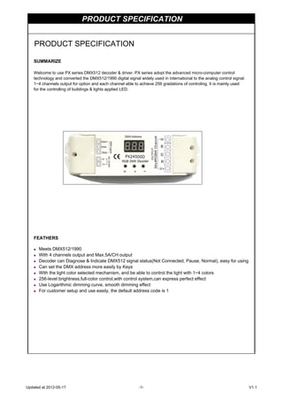


This document summarizes a PX series DMX512 decoder and driver that: 1. Converts DMX512/1990 digital signals to analog control signals and has 1-4 output channels with 256 levels of control. 2. Is used to control building and LED lights and has features like displaying DMX signal status and setting the DMX address using buttons. 3. Includes specifications like 4 decoding channels, 12-24V power supply, and interfaces for DMX signal, power, and driving RGBW modules or single-color LEDs.