08448380779 Call Girls In Friends Colony Women Seeking Men
High Power DMX Decoder & Driver Product Specification
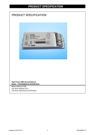
1. PRODUCT SPECIFICATION
High Power DMX Decoder&driver
Model:PX24500B(RJ45 INTERFACE)
Meets DMX512/1990
Can drive 3A(Each CH.)
Can drive many kinds of LED lamps
PRODUCT SPECIFICATION
Updated at 2012-03-14 -1- PX24500B-V1.0
2. DMX DECODER&DRIVER SERIES
SUMMARIZE
Thank you for using Px series DMX512 decoder.With advanced micro-computer control
technology,Px series convert the widely used DMX512/1990 signal to analog signal.Can
choose 1~3 output channel,256-level brightness control.For connecting of light console
and analog device,or lighting&building lamps controlling.
FEATHERS
◆ Meets DMX512/1990
◆ 256-level brightness,full-color control
◆ 3 output CH.,can drive 3A(Each CH.)
◆ With control system,can express perfect effect
◆ Can drive 1~3 channel of each lamp
◆ Can set the DMX addess freely
◆ High interference resistant,self-recovery function available
TECH. CHARACTERISTICS
Decode CH.: 1~3
Input Signal: DMX-512/1990 digital signal
Output Signal: 0~24V PWM signal,can drive3A(Each CH.)
Power Supply: DC,+12-24V
Power Dis.: <1W
Power Output: <216W(24V);<108W(12V)
Operating Temp.: 0~70℃
Size: 125(mm)*40(mm)*20(mm),can be custom-made
Weight: ≤62g
DIMENSION
PX24500B
Updated at 2012-03-14 -2- PX24500B-V1.0
3. DMX DECODER&DRIVER SERIES
Internal Block Digram
Appearance
(1) 、(2) DMX signal input&output interface(RJ45)
(3) Address setting interface
(4) Driver output interface
(5) Power input interface
Interface Introduction
◆ DMX signal interface
1: DATA+
2: DATA-
3-6: NC
7-8: GND
◆ Address setting interface
How to use See "DMX series of addresses dial code table"
◆ Power input interface
DC 12-24V input,supply power for decoder and the lamps it takes.
◆ Driver output interface
Common anode,V+ and R,G,B interface,can drive kinds of RGB module or single-color module,
Can regulate output current according to the actual load.
remark:
Connect the anode and RGB wire of common anode RGB module to the output interface of deoder directly;
Connect the anode wire of single-color module to V+ on decoder,and connect the cathode wire to one of RGB pin
according to the LED's color; Connect several colors single-color module to one decoder,please connect their
anode wires to V+ pin on decoder.
PX24500B
1
2
3
4
5
PX24500B
PX24500B
Updated at 2012-03-14 -3- PX24500B-V1.0
4. DMX DECODER&DRIVER SERIES
How To Use
PX24500B is controlled by DMX-512 digital signal。The frontage is DMX512 transmitter,
take EC-DMX512 for example,to control 0~24V analog devices.We suppose to drive LED
to introduce it.The connecting is below:
TYPICAL APPLICATIONS
◆ Circuit Diagram 1
Connecting of DMX-512 Signal
◆ The wire for DMX signal is STP,the DMX signal has positive and negative signal.
Pay attention to the polarity while soldering.Connect the positive signal,negative
signal and GND to the corresponding signal of PX24500B.
◆ Connect a signal terminal at the end of the whole connetion(To be PX24500B DIP switches set aside
under section 10 can)
PX24500B
PX24500B
Updated at 2012-03-14 -4- PX24500B-V1.0